EP0350017A1 - Obturateur avec indicateur de fuite - Google Patents
Obturateur avec indicateur de fuite Download PDFInfo
- Publication number
- EP0350017A1 EP0350017A1 EP89112297A EP89112297A EP0350017A1 EP 0350017 A1 EP0350017 A1 EP 0350017A1 EP 89112297 A EP89112297 A EP 89112297A EP 89112297 A EP89112297 A EP 89112297A EP 0350017 A1 EP0350017 A1 EP 0350017A1
- Authority
- EP
- European Patent Office
- Prior art keywords
- shut
- housing
- seals
- closing body
- dead space
- Prior art date
- Legal status (The legal status is an assumption and is not a legal conclusion. Google has not performed a legal analysis and makes no representation as to the accuracy of the status listed.)
- Granted
Links
- 238000007789 sealing Methods 0.000 claims description 11
- 239000003795 chemical substances by application Substances 0.000 claims description 9
- 239000003599 detergent Substances 0.000 claims description 9
- 238000011010 flushing procedure Methods 0.000 claims description 9
- 241000283216 Phocidae Species 0.000 description 35
- 238000004140 cleaning Methods 0.000 description 10
- 239000007788 liquid Substances 0.000 description 5
- 239000012459 cleaning agent Substances 0.000 description 3
- 239000000645 desinfectant Substances 0.000 description 2
- 230000015572 biosynthetic process Effects 0.000 description 1
- 238000010276 construction Methods 0.000 description 1
- 238000009795 derivation Methods 0.000 description 1
- 238000006073 displacement reaction Methods 0.000 description 1
- 230000000694 effects Effects 0.000 description 1
- 238000012423 maintenance Methods 0.000 description 1
- 230000014759 maintenance of location Effects 0.000 description 1
- 230000000149 penetrating effect Effects 0.000 description 1
- 238000000926 separation method Methods 0.000 description 1
- 230000035939 shock Effects 0.000 description 1
- 230000007704 transition Effects 0.000 description 1
Images


Classifications
-
- F—MECHANICAL ENGINEERING; LIGHTING; HEATING; WEAPONS; BLASTING
- F16—ENGINEERING ELEMENTS AND UNITS; GENERAL MEASURES FOR PRODUCING AND MAINTAINING EFFECTIVE FUNCTIONING OF MACHINES OR INSTALLATIONS; THERMAL INSULATION IN GENERAL
- F16K—VALVES; TAPS; COCKS; ACTUATING-FLOATS; DEVICES FOR VENTING OR AERATING
- F16K5/00—Plug valves; Taps or cocks comprising only cut-off apparatus having at least one of the sealing faces shaped as a more or less complete surface of a solid of revolution, the opening and closing movement being predominantly rotary
- F16K5/06—Plug valves; Taps or cocks comprising only cut-off apparatus having at least one of the sealing faces shaped as a more or less complete surface of a solid of revolution, the opening and closing movement being predominantly rotary with plugs having spherical surfaces; Packings therefor
- F16K5/0605—Plug valves; Taps or cocks comprising only cut-off apparatus having at least one of the sealing faces shaped as a more or less complete surface of a solid of revolution, the opening and closing movement being predominantly rotary with plugs having spherical surfaces; Packings therefor with particular plug arrangements, e.g. particular shape or built-in means
-
- F—MECHANICAL ENGINEERING; LIGHTING; HEATING; WEAPONS; BLASTING
- F16—ENGINEERING ELEMENTS AND UNITS; GENERAL MEASURES FOR PRODUCING AND MAINTAINING EFFECTIVE FUNCTIONING OF MACHINES OR INSTALLATIONS; THERMAL INSULATION IN GENERAL
- F16K—VALVES; TAPS; COCKS; ACTUATING-FLOATS; DEVICES FOR VENTING OR AERATING
- F16K37/00—Special means in or on valves or other cut-off apparatus for indicating or recording operation thereof, or for enabling an alarm to be given
-
- F—MECHANICAL ENGINEERING; LIGHTING; HEATING; WEAPONS; BLASTING
- F16—ENGINEERING ELEMENTS AND UNITS; GENERAL MEASURES FOR PRODUCING AND MAINTAINING EFFECTIVE FUNCTIONING OF MACHINES OR INSTALLATIONS; THERMAL INSULATION IN GENERAL
- F16K—VALVES; TAPS; COCKS; ACTUATING-FLOATS; DEVICES FOR VENTING OR AERATING
- F16K5/00—Plug valves; Taps or cocks comprising only cut-off apparatus having at least one of the sealing faces shaped as a more or less complete surface of a solid of revolution, the opening and closing movement being predominantly rotary
- F16K5/06—Plug valves; Taps or cocks comprising only cut-off apparatus having at least one of the sealing faces shaped as a more or less complete surface of a solid of revolution, the opening and closing movement being predominantly rotary with plugs having spherical surfaces; Packings therefor
Definitions
- the invention relates to a shut-off element which can be inserted between two lines and has a leakage indicator.
- shut-off devices are used, for example, in cases in which a separation of product liquid and cleaning solution must be provided. So far, special designs of flap valves and poppet valves have been used for this. In both cases, measures must be taken to seal the leakage outlet when the valve is open.
- the invention is based on the need for a shut-off element with a leakage indicator that works properly and avoids an expensive special construction.
- a ball valve is provided as a shut-off device with a spherical closing body sealed between the two sides in the flow direction of the medium by inserted in the connecting piece of the valve housing and secured by ring seals trapped by attachable connecting flanges, of which between the housing , the seals and the closing body formed a dead space leading to the outside leakage line.
- the solution according to the invention takes advantage of the advantages inherent in the ball valve, in particular its pressure shock resistance and the maintenance of the full line cross section in the shut-off device. Since the valve opens and closes continuously, there are no pressure surges when switching.
- Leakage discharge can take place directly through the wall of the housing; in the case of a closing body mounted on both sides of the housing, the design of the bearing pin on the side facing away from the actuating spindle from the closing body as the penetrating through the housing wall to the dead space between the housing, the seals, is available for leakage derivation and the closing body through hollow shaft.
- a flushing agent supply line is provided to the dead space of the ball valve, through which the flushing agent, steam and, if appropriate, then also disinfectant solutions are introduced into the dead space, the discharge of which takes place via the leakage line.
- the cleaning treatment can advantageously be carried out in any switching position of the ball valve.
- the simplest solution is a flushing agent supply line which directly affects the dead space of the ball valve.
- a flushing agent supply line which flows tangentially into the dead space at a distance from the leakage line above the leakage line, advantageously results in a circulating rinse which penetrates the dead space and has an improved cleaning effect.
- the leakage line located in the deepest area of the dead space can also run tangentially to the ball valve housing.
- the spindle of the ball valve with which the closing body is actuated, is provided as a hollow shaft which is closed at the free end and has passages to the dead space of the ball valve, a detergent feed line being connected to the spindle in the projection above the ball valve, for example such that the detergent supply line in a liquid-tight penetrated by the spindle Ring channel runs out and the spindle wall lying in the area of the ring channel is provided with passages.
- the free cross section of the passages of the spindle to the dead space of the ball valve is designed to be smaller than that of the passages from the dead space to the bearing journal with the leakage line extending through it.
- the seals for the closing body which are made of a dimensionally stable plastic and are to be incorporated into the connecting piece of the valve housing, have a length which leaves a gap between them and the connecting flanges which can be attached to the connecting piece and which a between the flange-side end face of the seals and the connecting flanges extending spring element bridged, wherein between the seals and the inner wall of the connecting piece a closing body side of the connecting piece and on the opposite side of the seal is formed an annular space into which a pressure medium supply line opens.
- the seals are lifted off the closing body and the sealing surfaces of the seals, as well as the corresponding areas of the closing body, are cleaned by the detergent present in the main line, which is caused by the between the seals and the clasp body-forming columns flows into the dead space of the ball valve. Under certain circumstances it is then also possible to dispense with an independent detergent supply line to the dead space. If the circumstances so require, one sealing area can be cleaned first and then the other sealing area.
- the spring element imparting its functional position to the closing body seal can be a soft seal projecting over the closing body seal and coming into contact with the connecting flange.
- the required sealing of the annular space is effected on both sides of the annular space formed in the closing body seal, which is made of a suitable dimensionally stable plastic, into the closing body seal.
- the leakage line and then possibly the flushing agent line can of course also be provided with a shut-off device, be it that a retention of the flushing agent in the areas of the ball valve to be cleaned is desired, either in order to shield the cleaned areas from external influences.
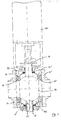
- the shut-off valve forming ball valve in Figures 1 and 2 is in a known manner from the housing 11 with the connecting piece 111, 111 ', the Closing body 12, the seals 13, 13 ', the connecting flanges 14, 14' and the spindle 16 together.
- the closing body 12 is provided on the side facing away from the spindle 16 with a hollow bearing pin 17 which extends outward through the housing 11 and which, in its area in the housing 11, has passages 171 to the dead space 112 between the housing 11, the seals 13, 13 'and the closing body 12 is provided.
- the passage for the bearing pin 17 in the housing 11 is designed and sealed in accordance with the spindle passage.
- a spindle drive 161 acts on the spindle. This does not rule out manual operation of the valve.
- the leakage discharge can also take place elsewhere in the housing 11 'directly to the outside. It will of course let the leakage line 19 start from the lowest possible point on the housing 11 '.
- the shut-off device according to Figures 4 and 5 is also formed by a ball valve, which is again from a housing 21 with connecting piece 211, 211 ', the seals 23, 23', the closing body 22, the connecting flanges 24, 24 'of the spindle 26th and the hollow bearing journal 27, which extends in the opposite direction to the spindle 26 through the housing 21 and extends outwards. Due to the inside of the housing via passages 271 with the dead space 212 between the housing 21, the seals 23, 23 'connected, from the closing body 22 outgoing hollow bearing pin 27 leakage liquid (arrow sequence CC or C'-C' in Fig. 5) shows that The ball valve is leaking.
- the likewise hollow spindle 26, which is also connected in the interior of the housing again via passages 262 to the dead space 212 between the housing 21, the seals 23, 23 'and the closing body 22 and at the projection thereof via the housing 21 via an annular channel 264 surrounding this projection a supply line 263, opens the possibility of the dead space 212 between the housing 21, the seals 23 23 'and the closing body 22 by means of the supply line 263, the annular channel 264, passages 266 in the spindle wall, the hollow spindle 26 and in the To act upon the passages 262 opening in the dead space 212 in the spindle wall with cleaning liquid or disinfectant solution, which then also emerges again through the hollow bearing journal 27 (arrow sequence DD in FIG. 5)
- the end of the hollow spindle 26 is designated at its free end, which transitions into the spindle drive 269.
- a and B denote different products in the lines connected to the ball valve.
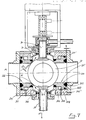
- the design of the new shut-off element according to FIG. 7 opens up the possibility of cleaning the valve seat both on the seal side and on the closing body side.
- the closing body seals 33, 33 ' are designed in a special way.
- the actual, in the connecting piece 311, 311 'of the ball valve housing 31 incorporated closing body seals are dimensionally stable plastic sleeves 331, 331' of a length, which in the functional position of the seals leave a gap S between them and the trailing connecting flanges 314, 314 ', which by a in it is bridged in soft seal 332.
- annular space 333 into which a pressure medium line 334 opens. If the annular spaces 333 of the seal 33 or the seal 33 'are pressurized, there is a displacement of the sealing body, for example 331, in the connecting piece 311 in the direction of arrow E, as indicated on the left in FIG. 7.
- the original distance S of the sealing body 331 or 331 'from the connecting flange 314 or 314' corresponds to the formation of a gap S 'between the sealing body 331 and the closing body 32, by the pending cleaning agent A in the between the Housing 31, the seals 33, 33 'and the closing body 32 formed dead space 312 while cleaning the sealing surfaces 321 and 338 on the one hand of the closing body 32 and on the other hand of the sealing body 331 and 331' flows, the dead space 312 through the leakage discharge, i.e. the hollow bearing journal 317 leaves again.
- This type of cleaning can be carried out in addition to the dead space cleaning by means of cleaning agents introduced into the dead space through the hollow spindle, if the conditions permit, but in this case a separate cleaning by means of cleaning agents supplied by the spindle can also be dispensed with.
Landscapes
- Engineering & Computer Science (AREA)
- General Engineering & Computer Science (AREA)
- Mechanical Engineering (AREA)
- Taps Or Cocks (AREA)
- Clamps And Clips (AREA)
- Pipe Accessories (AREA)
Priority Applications (1)
| Application Number | Priority Date | Filing Date | Title |
|---|---|---|---|
| AT89112297T ATE102689T1 (de) | 1988-07-05 | 1989-07-05 | Absperrorgan mit leckageanzeige. |
Applications Claiming Priority (4)
| Application Number | Priority Date | Filing Date | Title |
|---|---|---|---|
| DE8808574U | 1988-07-05 | ||
| DE8808574U DE8808574U1 (de) | 1988-07-05 | 1988-07-05 | Absperrorgan mit Leckageanzeige |
| DE8810104U | 1988-08-09 | ||
| DE8810104U DE8810104U1 (de) | 1988-08-09 | 1988-08-09 | Absperrorgan mit Leckageanzeige |
Publications (2)
| Publication Number | Publication Date |
|---|---|
| EP0350017A1 true EP0350017A1 (fr) | 1990-01-10 |
| EP0350017B1 EP0350017B1 (fr) | 1994-03-09 |
Family
ID=25953255
Family Applications (1)
| Application Number | Title | Priority Date | Filing Date |
|---|---|---|---|
| EP89112297A Expired - Lifetime EP0350017B1 (fr) | 1988-07-05 | 1989-07-05 | Obturateur avec indicateur de fuite |
Country Status (3)
| Country | Link |
|---|---|
| EP (1) | EP0350017B1 (fr) |
| DE (1) | DE58907157D1 (fr) |
| ES (1) | ES2050190T3 (fr) |
Cited By (11)
| Publication number | Priority date | Publication date | Assignee | Title |
|---|---|---|---|---|
| FR2755209A1 (fr) * | 1996-10-30 | 1998-04-30 | Lartigue Patrick | Dispositif de controle d'etancheite pour un organe obturateur du type robinet et/ou vanne |
| WO2003067131A1 (fr) * | 2002-02-08 | 2003-08-14 | Fisher Controls International Llc | Bague de siege en une piece pour sanitaire |
| FR2841958A1 (fr) * | 2002-07-04 | 2004-01-09 | Air Liquide | Dispositif d'isolement sous forme de robinet a boisseau spherique |
| RU2243437C2 (ru) * | 2002-12-02 | 2004-12-27 | Закрытое акционерное общество "ФОБОС" | Шаровой кран |
| WO2008054242A1 (fr) * | 2006-11-03 | 2008-05-08 | Oktrytoe Aktsionernoe Obschestvo 'volgoradneftemash' | Robinet à tournant sphérique destiné à la collecte de condensat |
| DE102008057683B3 (de) * | 2008-11-17 | 2010-07-29 | Marinus Cornelis Adrianus Heij | Rohrschließvorrichtung einer Maschine |
| WO2010085798A1 (fr) * | 2009-01-26 | 2010-07-29 | Process Pigging Systems, Llc | Clapet à bille à joint d'étanchéité rétractable |
| CN102416387A (zh) * | 2011-09-27 | 2012-04-18 | 华北电网有限公司北京十三陵蓄能电厂 | 球阀检修密封在线清洗装置及方法 |
| JP2015113946A (ja) * | 2013-12-13 | 2015-06-22 | 株式会社キッツ | スラリー排出機能付きボールバルブとそのバルブキャビティからのスラリー排出方法 |
| CN107727316A (zh) * | 2017-10-26 | 2018-02-23 | 方正阀门集团有限公司 | 固定球阀密封性能检测装置 |
| EP2672153B1 (fr) * | 2012-06-05 | 2019-08-07 | Delta Systemtechnik GmbH | Robinet à boisseau sphérique |
Citations (5)
| Publication number | Priority date | Publication date | Assignee | Title |
|---|---|---|---|---|
| FR703758A (fr) * | 1930-10-16 | 1931-05-06 | Zimmermann & Jansen Gmbh | Dispositif d'évacuation de l'air pour les vannes d'arrêt |
| GB1173090A (en) * | 1966-06-10 | 1969-12-03 | Hills Mccanna Co | Ball Valves |
| FR2091174A5 (fr) * | 1970-05-04 | 1972-01-14 | Grove Valve & Regulator Co | |
| DE2803818A1 (de) * | 1978-01-28 | 1979-08-02 | Nocado Armaturenfab Gmbh & Co | Ventilkoerper, insbesondere fuer ein scheibenventil |
| WO1987000597A1 (fr) * | 1985-07-23 | 1987-01-29 | Ruhrgas Aktiengesellschaft | Garniture d'arret sous forme de robinet a boisseau spherique |
-
1989
- 1989-07-05 ES ES89112297T patent/ES2050190T3/es not_active Expired - Lifetime
- 1989-07-05 DE DE89112297T patent/DE58907157D1/de not_active Expired - Lifetime
- 1989-07-05 EP EP89112297A patent/EP0350017B1/fr not_active Expired - Lifetime
Patent Citations (5)
| Publication number | Priority date | Publication date | Assignee | Title |
|---|---|---|---|---|
| FR703758A (fr) * | 1930-10-16 | 1931-05-06 | Zimmermann & Jansen Gmbh | Dispositif d'évacuation de l'air pour les vannes d'arrêt |
| GB1173090A (en) * | 1966-06-10 | 1969-12-03 | Hills Mccanna Co | Ball Valves |
| FR2091174A5 (fr) * | 1970-05-04 | 1972-01-14 | Grove Valve & Regulator Co | |
| DE2803818A1 (de) * | 1978-01-28 | 1979-08-02 | Nocado Armaturenfab Gmbh & Co | Ventilkoerper, insbesondere fuer ein scheibenventil |
| WO1987000597A1 (fr) * | 1985-07-23 | 1987-01-29 | Ruhrgas Aktiengesellschaft | Garniture d'arret sous forme de robinet a boisseau spherique |
Cited By (15)
| Publication number | Priority date | Publication date | Assignee | Title |
|---|---|---|---|---|
| FR2755209A1 (fr) * | 1996-10-30 | 1998-04-30 | Lartigue Patrick | Dispositif de controle d'etancheite pour un organe obturateur du type robinet et/ou vanne |
| WO2003067131A1 (fr) * | 2002-02-08 | 2003-08-14 | Fisher Controls International Llc | Bague de siege en une piece pour sanitaire |
| US6655659B2 (en) | 2002-02-08 | 2003-12-02 | Fisher Controls International Inc. | One-piece sanitary seat ring |
| FR2841958A1 (fr) * | 2002-07-04 | 2004-01-09 | Air Liquide | Dispositif d'isolement sous forme de robinet a boisseau spherique |
| RU2243437C2 (ru) * | 2002-12-02 | 2004-12-27 | Закрытое акционерное общество "ФОБОС" | Шаровой кран |
| RU2327073C1 (ru) * | 2006-11-03 | 2008-06-20 | Открытое акционерное общество "Волгограднефтемаш" | Шаровой кран-конденсатосборщик |
| WO2008054242A1 (fr) * | 2006-11-03 | 2008-05-08 | Oktrytoe Aktsionernoe Obschestvo 'volgoradneftemash' | Robinet à tournant sphérique destiné à la collecte de condensat |
| DE102008057683B3 (de) * | 2008-11-17 | 2010-07-29 | Marinus Cornelis Adrianus Heij | Rohrschließvorrichtung einer Maschine |
| WO2010085798A1 (fr) * | 2009-01-26 | 2010-07-29 | Process Pigging Systems, Llc | Clapet à bille à joint d'étanchéité rétractable |
| CN102416387A (zh) * | 2011-09-27 | 2012-04-18 | 华北电网有限公司北京十三陵蓄能电厂 | 球阀检修密封在线清洗装置及方法 |
| CN102416387B (zh) * | 2011-09-27 | 2014-07-23 | 国家电网公司 | 球阀检修密封在线清洗装置及方法 |
| EP2672153B1 (fr) * | 2012-06-05 | 2019-08-07 | Delta Systemtechnik GmbH | Robinet à boisseau sphérique |
| JP2015113946A (ja) * | 2013-12-13 | 2015-06-22 | 株式会社キッツ | スラリー排出機能付きボールバルブとそのバルブキャビティからのスラリー排出方法 |
| CN107727316A (zh) * | 2017-10-26 | 2018-02-23 | 方正阀门集团有限公司 | 固定球阀密封性能检测装置 |
| CN107727316B (zh) * | 2017-10-26 | 2023-05-12 | 方正阀门集团股份有限公司 | 固定球阀密封性能检测装置 |
Also Published As
| Publication number | Publication date |
|---|---|
| EP0350017B1 (fr) | 1994-03-09 |
| ES2050190T3 (es) | 1994-05-16 |
| DE58907157D1 (de) | 1994-04-14 |
Similar Documents
| Publication | Publication Date | Title |
|---|---|---|
| DE3126507C2 (fr) | ||
| DE3242947C2 (fr) | ||
| DE4118874A1 (de) | Verfahren zur reinigung eines leckagefrei schaltenden doppelsitzventils und ventilvorrichtung zum durchfuehren des verfahrens | |
| WO1998041786A1 (fr) | Soupape a double siege nettoyable | |
| DE102004008879A1 (de) | Filtervorrichtung | |
| DE3300217A1 (de) | Stroemungssteuerungsventil | |
| EP0350017A1 (fr) | Obturateur avec indicateur de fuite | |
| DE1650435A1 (de) | Kugelhahn | |
| DE3242763A1 (de) | Adapter fuer einen ventilzaehler | |
| DE19608792C2 (de) | Sitzreinigungsfähiges Doppelsitzventil | |
| EP0337519A2 (fr) | Procédé et dispositif de protection et de support d'un joint d'étanchéité d'une vanne | |
| DE2644225A1 (de) | Kugelhahn fuer druckmittelanlagen | |
| EP0650321B1 (fr) | Vanne pour le retrolavage des gobelets trayeurs des machines a traire | |
| EP1103753B1 (fr) | Vanne à trois voies nettoyable par un racleur | |
| DE60011258T2 (de) | Vorrichtung für einen Behälter | |
| EP0740083B1 (fr) | Vanne d'arrêt avec une piston de vanne distributrice | |
| DE3313539A1 (de) | Filtereinheit | |
| DE962485C (de) | Absperrvorrichtung, bei der Einlaufleitung und Auslaufleitung konzentrisch oder unmittelbar nebeneinander angeordnet sind | |
| DE19842603A1 (de) | Sitzreinigungsfähiges Doppelsitzventil | |
| DE2312883A1 (de) | Ventil | |
| DE3030447A1 (de) | Mehrwegehahn, insbesondere dreiwegehahn | |
| DE19822424A1 (de) | Doppelsitzventil mit Leckkontrolle | |
| EP0928915A2 (fr) | Soupape à siège double pour contrÔler des fuites | |
| DE29923799U1 (de) | Doppelsitzventil mit spülfähiger Ventilstangendurchführung am Ventilgehäuse | |
| DE3000592A1 (de) | Steuerventil |
Legal Events
| Date | Code | Title | Description |
|---|---|---|---|
| PUAI | Public reference made under article 153(3) epc to a published international application that has entered the european phase |
Free format text: ORIGINAL CODE: 0009012 |
|
| AK | Designated contracting states |
Kind code of ref document: A1 Designated state(s): AT BE CH DE ES FR GB GR IT LI LU NL SE |
|
| 17P | Request for examination filed |
Effective date: 19891208 |
|
| 17Q | First examination report despatched |
Effective date: 19910514 |
|
| GRAA | (expected) grant |
Free format text: ORIGINAL CODE: 0009210 |
|
| AK | Designated contracting states |
Kind code of ref document: B1 Designated state(s): AT BE CH DE ES FR GB GR IT LI LU NL SE |
|
| REF | Corresponds to: |
Ref document number: 102689 Country of ref document: AT Date of ref document: 19940315 Kind code of ref document: T |
|
| ITF | It: translation for a ep patent filed | ||
| GBT | Gb: translation of ep patent filed (gb section 77(6)(a)/1977) |
Effective date: 19940311 |
|
| REF | Corresponds to: |
Ref document number: 58907157 Country of ref document: DE Date of ref document: 19940414 |
|
| REG | Reference to a national code |
Ref country code: ES Ref legal event code: FG2A Ref document number: 2050190 Country of ref document: ES Kind code of ref document: T3 |
|
| ET | Fr: translation filed | ||
| EPTA | Lu: last paid annual fee | ||
| REG | Reference to a national code |
Ref country code: GR Ref legal event code: FG4A Free format text: 3011977 |
|
| PLBE | No opposition filed within time limit |
Free format text: ORIGINAL CODE: 0009261 |
|
| STAA | Information on the status of an ep patent application or granted ep patent |
Free format text: STATUS: NO OPPOSITION FILED WITHIN TIME LIMIT |
|
| EAL | Se: european patent in force in sweden |
Ref document number: 89112297.0 |
|
| 26N | No opposition filed | ||
| REG | Reference to a national code |
Ref country code: GB Ref legal event code: IF02 |
|
| PGFP | Annual fee paid to national office [announced via postgrant information from national office to epo] |
Ref country code: LU Payment date: 20070705 Year of fee payment: 19 |
|
| PGFP | Annual fee paid to national office [announced via postgrant information from national office to epo] |
Ref country code: AT Payment date: 20070615 Year of fee payment: 19 |
|
| PGFP | Annual fee paid to national office [announced via postgrant information from national office to epo] |
Ref country code: ES Payment date: 20080728 Year of fee payment: 20 Ref country code: DE Payment date: 20080829 Year of fee payment: 20 Ref country code: CH Payment date: 20080730 Year of fee payment: 20 |
|
| PGFP | Annual fee paid to national office [announced via postgrant information from national office to epo] |
Ref country code: NL Payment date: 20080724 Year of fee payment: 20 Ref country code: IT Payment date: 20080728 Year of fee payment: 20 Ref country code: FR Payment date: 20080729 Year of fee payment: 20 |
|
| PGFP | Annual fee paid to national office [announced via postgrant information from national office to epo] |
Ref country code: GB Payment date: 20080729 Year of fee payment: 20 |
|
| PGFP | Annual fee paid to national office [announced via postgrant information from national office to epo] |
Ref country code: BE Payment date: 20080818 Year of fee payment: 20 Ref country code: SE Payment date: 20080729 Year of fee payment: 20 |
|
| PG25 | Lapsed in a contracting state [announced via postgrant information from national office to epo] |
Ref country code: AT Free format text: LAPSE BECAUSE OF NON-PAYMENT OF DUE FEES Effective date: 20080705 |
|
| PGFP | Annual fee paid to national office [announced via postgrant information from national office to epo] |
Ref country code: GR Payment date: 20080729 Year of fee payment: 20 |
|
| REG | Reference to a national code |
Ref country code: CH Ref legal event code: PL |
|
| REG | Reference to a national code |
Ref country code: GB Ref legal event code: PE20 Expiry date: 20090704 |
|
| NLV7 | Nl: ceased due to reaching the maximum lifetime of a patent |
Effective date: 20090705 |
|
| EUG | Se: european patent has lapsed | ||
| REG | Reference to a national code |
Ref country code: ES Ref legal event code: FD2A Effective date: 20090706 |
|
| PG25 | Lapsed in a contracting state [announced via postgrant information from national office to epo] |
Ref country code: ES Free format text: LAPSE BECAUSE OF EXPIRATION OF PROTECTION Effective date: 20090706 |
|
| PG25 | Lapsed in a contracting state [announced via postgrant information from national office to epo] |
Ref country code: NL Free format text: LAPSE BECAUSE OF EXPIRATION OF PROTECTION Effective date: 20090705 Ref country code: GB Free format text: LAPSE BECAUSE OF EXPIRATION OF PROTECTION Effective date: 20090704 |
|
| PG25 | Lapsed in a contracting state [announced via postgrant information from national office to epo] |
Ref country code: LU Free format text: LAPSE BECAUSE OF NON-PAYMENT OF DUE FEES Effective date: 20080705 |