EP0350258A2 - Têtes d'impression matricielles par points - Google Patents
Têtes d'impression matricielles par points Download PDFInfo
- Publication number
- EP0350258A2 EP0350258A2 EP89306778A EP89306778A EP0350258A2 EP 0350258 A2 EP0350258 A2 EP 0350258A2 EP 89306778 A EP89306778 A EP 89306778A EP 89306778 A EP89306778 A EP 89306778A EP 0350258 A2 EP0350258 A2 EP 0350258A2
- Authority
- EP
- European Patent Office
- Prior art keywords
- dot
- actuating position
- flexible member
- printing
- devices
- Prior art date
- Legal status (The legal status is an assumption and is not a legal conclusion. Google has not performed a legal analysis and makes no representation as to the accuracy of the status listed.)
- Granted
Links
Images


Classifications
-
- B—PERFORMING OPERATIONS; TRANSPORTING
- B41—PRINTING; LINING MACHINES; TYPEWRITERS; STAMPS
- B41J—TYPEWRITERS; SELECTIVE PRINTING MECHANISMS, i.e. MECHANISMS PRINTING OTHERWISE THAN FROM A FORME; CORRECTION OF TYPOGRAPHICAL ERRORS
- B41J2/00—Typewriters or selective printing mechanisms characterised by the printing or marking process for which they are designed
- B41J2/22—Typewriters or selective printing mechanisms characterised by the printing or marking process for which they are designed characterised by selective application of impact or pressure on a printing material or impression-transfer material
- B41J2/23—Typewriters or selective printing mechanisms characterised by the printing or marking process for which they are designed characterised by selective application of impact or pressure on a printing material or impression-transfer material using print wires
- B41J2/27—Actuators for print wires
- B41J2/295—Actuators for print wires using piezoelectric elements
-
- H—ELECTRICITY
- H02—GENERATION; CONVERSION OR DISTRIBUTION OF ELECTRIC POWER
- H02N—ELECTRIC MACHINES NOT OTHERWISE PROVIDED FOR
- H02N2/00—Electric machines in general using piezoelectric effect, electrostriction or magnetostriction
- H02N2/02—Electric machines in general using piezoelectric effect, electrostriction or magnetostriction producing linear motion, e.g. actuators; Linear positioners ; Linear motors
- H02N2/04—Constructional details
- H02N2/043—Mechanical transmission means, e.g. for stroke amplification
-
- H—ELECTRICITY
- H10—SEMICONDUCTOR DEVICES; ELECTRIC SOLID-STATE DEVICES NOT OTHERWISE PROVIDED FOR
- H10N—ELECTRIC SOLID-STATE DEVICES NOT OTHERWISE PROVIDED FOR
- H10N30/00—Piezoelectric or electrostrictive devices
- H10N30/50—Piezoelectric or electrostrictive devices having a stacked or multilayer structure
-
- H—ELECTRICITY
- H10—SEMICONDUCTOR DEVICES; ELECTRIC SOLID-STATE DEVICES NOT OTHERWISE PROVIDED FOR
- H10N—ELECTRIC SOLID-STATE DEVICES NOT OTHERWISE PROVIDED FOR
- H10N30/00—Piezoelectric or electrostrictive devices
- H10N30/80—Constructional details
Definitions
- This invention relates to dot matrix printing heads.
- actuators comprising electro or magnetic-distortion devices have been developed and used instead of electromagnet type drive elements.
- electro-distortion devices in a printing head has been proposed in "NIKKEI (Japan Economic) MECHANICAL", page 92, March 12, 1984, for example, the proposed electro-distortion device being made by the steps of: preparing a plurality of green sheets made of piezo-electric ceramics, forming a metal paste film on one of the surfaces of each of the green sheets to form an inner electrode, and laminating and sintering the plurality of green sheets.
- a printing head using such an actuating device must be provided with means for effectively enlarging the very small displacements of such an actuating element so as to drive the dot-impact wires or rods adequately.
- An embodiment of a first aspect of the present invention provides a printing head which comprises: a head base; a plurality of printing members constituting a dot matrix, and a plurality of actuators for driving the printing members, respectively; each of the actuators comprising: a resiliently movable member having one free end to which the printing member is connected and the other end fixedly secured to the head base at a fixing point; the movable member having an actuating position in the vicinity of the fixing point such that a distance from the actuating position to the fixing point is much smaller than a distance from actuating position to the free end; and an actuating device for exerting a displacement of the movable member at the actuating position so that the displacement is enlarged at the one free end to drive the printing member; characterized in that the movable member is a flat material extending substantially perpendicular to a direction of the displacement of the movable member; and the movable member is shaped substantially, between the actuating position and the fixing point, as one or more triangles
- An embodiment of a second aspect of the present invention provides an electro-distortion device used as a piezo actuator, the device comprising: a plurality of sheets made of an electro-distortion material and laminated via electrodes, an insulation material enveloping the plurality of sheets and electrodes, a metal cover enveloping the insulation material, and means for energizing an electric voltage between the adjacent electrodes, so that the device generates a strain or displacement in a direction of lamination of the plurality of sheets when an electric power is applied between the adjacent electrodes.
- Figure 1 shows a printing head 10 of a dot-impact printer, comprising a cylindrical housing 20 and a plurality of printing devices 30 arrayed around and extending radially within the cylindrical housing 20.
- each of the devices 30 comprises a base member 1, a movable member 11, and an actuator (electro-distortion device) 3.
- the movable member 11 comprises a flat leaf spring made of an appropriate resilient material having one end rigidly secured to the base member 1 at a fixing position B and a free remote end on which a dot-printing member (dot-printing pin or wire) 4 is mounted. A predetermined number of such dot-printing members 4 cooperate to constitute a dot matrix.
- the movable member 11 is gradually tapered, along substantially its entire length, from the fixing position B to the free end thereof.
- the actuator 3 has one end rigidly secured to the base member 1 and the other end connected via a connecting member 5 to the movable member 11 at an actuating position A thereof.
- the actuating position A is relatively near to the position B at which the movable member 11 is fixed to the base member 1.
- the region of the laminar movable member 11 that extends from the actuating position A to the fixing position B comprises two substantially triangular portions arranged laterally adjacent to one another, each of the portions having a base at the fixing position B and a truncated apex at the actuating position A. These two lateral portions are separated, as seen in the plan view, by a triangular-form aperture 12, having a base at the actuating position A and an apex at the fixing position B or in the vicinity thereof. In general, at least one such triangular-form aperture is desirable. As shown in the plan view of Figure 2A, the remaining part of the movable member 11 is gradually tapered from the actuating position A to the free end thereof.
- the dot-printing member 4 is moved upward as shown by an arrow P in Figure 2B to perform a printing operation.
- the electric power supply to the actuator 3 is stopped just before the completion of the printing operation, and thus, after completion of printing, the movable member 2 is returned to the original position by the actuator 3.
- the width of the movable member 2 of the comparative example is substantially constant from the fixing position B to the actuating position A, and is gradually reduced from the actuating position A to the free remote end on which the dot-printing member 4 is rigidly mounted.
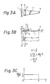
- the distortion mode in the movable member 11 is different from that of the member 2 of Figure 4A in that the angle through which the movable member 11 distorts at the actuating portion when resiliently deformed is greater than that of the member 2.
- the center of rotation O2 of the movable member 11 is shifted toward the actuating position A, and thus the enlargement factor of the displacement at A is increased.
- the distribution of stress is substantially uniform between the fixing position B and the actuating position A, the magnitude of the stress being defined by the relation which is smaller than the maximum stress shown in Figure 4C.
- an embodiment of the present invention can provide a high speed reliable printing head wherein the printing members are provided with sufficient stroke length and the distribution of stress is substantially uniform.
- FIG. 5 illustrates an electro-distortion device suitable for use as an actuator for driving a dot-impact printing wire or rod in the printing head of Figure 1.
- This electro-distortion device comprises a plurality of sheets 21 made of an electro-distortion material, such as a piezo-electric ceramic, and stacked together with laminar electrodes 22 therebetween.
- a first group of alternately arranged electrodes 22 are connected to a lead 24a and insulated from the other electrodes 22 by beads 25 made of an electrically insulating material, such as glass.
- the other group of alternate electrodes 22 are connected to a second lead 24b and insulated from the first group of electrodes 22 in the same manner as above.
- the laminations comprising the sheets of electro-distortion material 21 and the electrodes 22 are enclosed within an insulating resin material 23, such as an epoxy resin.
- an operating voltage is applied between the leads 24a and 24b, causing longitudinal electrostrictive expansion or contraction of the stack of laminations, the top of that stack being connected to the resilient member 11 of Figure 2B, for example, and the bottom of the stack being fixed to or mounted on a lower part of the base member 1.
- the insulating resin material 23 is itself also enveloped in a metal cover 31.
- This metal cover 31 can be formed by vaporizing an appropriate metal, such as aluminum, onto the insulating resin material 23, thus inhibiting the ingress of moisture into the electro-distortion device by virtue of the high moisture-proof characteristics of such a metal cover.
- the insulating resin material 23 prevents short-circuits between adjacent electrodes 22 that would otherwise be caused by the metal cover 31. As a result, the electrodes 22 are not prone to becoming electrically connected to each other due to migration effects for example, even if the device is used in a moist environment, so that the device has a desirably high inherent reliability.
Landscapes
- Impact Printers (AREA)
Priority Applications (1)
| Application Number | Priority Date | Filing Date | Title |
|---|---|---|---|
| EP93115068A EP0587192B1 (fr) | 1988-07-08 | 1989-07-04 | Dispositif électro-déformable |
Applications Claiming Priority (4)
| Application Number | Priority Date | Filing Date | Title |
|---|---|---|---|
| JP168894/88 | 1988-07-08 | ||
| JP16889488A JP2608463B2 (ja) | 1988-07-08 | 1988-07-08 | 印字ヘッド |
| JP283897/88 | 1988-11-11 | ||
| JP63283897A JPH02130970A (ja) | 1988-11-11 | 1988-11-11 | 電歪素子 |
Related Child Applications (1)
| Application Number | Title | Priority Date | Filing Date |
|---|---|---|---|
| EP93115068.4 Division-Into | 1989-07-04 |
Publications (3)
| Publication Number | Publication Date |
|---|---|
| EP0350258A2 true EP0350258A2 (fr) | 1990-01-10 |
| EP0350258A3 EP0350258A3 (en) | 1990-09-05 |
| EP0350258B1 EP0350258B1 (fr) | 1994-04-13 |
Family
ID=26492416
Family Applications (2)
| Application Number | Title | Priority Date | Filing Date |
|---|---|---|---|
| EP89306778A Expired - Lifetime EP0350258B1 (fr) | 1988-07-08 | 1989-07-04 | Têtes d'impression matricielles par points |
| EP93115068A Expired - Lifetime EP0587192B1 (fr) | 1988-07-08 | 1989-07-04 | Dispositif électro-déformable |
Family Applications After (1)
| Application Number | Title | Priority Date | Filing Date |
|---|---|---|---|
| EP93115068A Expired - Lifetime EP0587192B1 (fr) | 1988-07-08 | 1989-07-04 | Dispositif électro-déformable |
Country Status (6)
| Country | Link |
|---|---|
| US (1) | US5092689A (fr) |
| EP (2) | EP0350258B1 (fr) |
| KR (1) | KR940007208B1 (fr) |
| CA (1) | CA1331313C (fr) |
| DE (2) | DE68927500T2 (fr) |
| ES (1) | ES2050804T3 (fr) |
Cited By (1)
| Publication number | Priority date | Publication date | Assignee | Title |
|---|---|---|---|---|
| EP0768184A2 (fr) | 1992-06-23 | 1997-04-16 | Fujitsu Limited | Tête d'impression par points à aiguilles |
Families Citing this family (7)
| Publication number | Priority date | Publication date | Assignee | Title |
|---|---|---|---|---|
| JPH04347656A (ja) * | 1991-05-27 | 1992-12-02 | Fujitsu Ltd | 圧電素子型アクチュエータ |
| JP2965763B2 (ja) * | 1991-10-09 | 1999-10-18 | 富士通株式会社 | 圧電素子型アクチュエータの保持構造 |
| JPH05147237A (ja) * | 1991-11-18 | 1993-06-15 | Fujitsu Ltd | 印字ヘツド |
| JP2525528B2 (ja) * | 1991-11-19 | 1996-08-21 | 富士通株式会社 | 圧電アクチュエ―タ |
| DE19928185B4 (de) * | 1999-06-19 | 2006-05-24 | Robert Bosch Gmbh | Piezoaktor |
| JP2002203998A (ja) * | 2000-12-28 | 2002-07-19 | Denso Corp | 圧電体素子及びその製造方法 |
| DE102006019900A1 (de) * | 2006-04-28 | 2007-11-08 | Siemens Ag | Piezoaktor mit Gradient-Verkapselungsschicht und Verfahren zu seiner Herstellung |
Family Cites Families (21)
| Publication number | Priority date | Publication date | Assignee | Title |
|---|---|---|---|---|
| JPS5427814A (en) * | 1977-07-29 | 1979-03-02 | Sharp Kk | Printing head with image segments |
| JPS55150284A (en) * | 1979-05-11 | 1980-11-22 | Ngk Spark Plug Co Ltd | Piezoelectric element |
| JPS578167A (en) * | 1980-06-18 | 1982-01-16 | Toshiba Corp | Armature of printing head |
| JPS57191073A (en) * | 1981-05-21 | 1982-11-24 | Fujitsu Ltd | Driver for impact printer |
| JPS58188672A (ja) * | 1982-04-30 | 1983-11-04 | Nec Corp | 印字ユニツト |
| JPS57193375A (en) * | 1981-05-26 | 1982-11-27 | Nec Corp | Impact printing head |
| US4362407A (en) * | 1981-09-08 | 1982-12-07 | Piezo Electric Products, Inc. | Piezoelectric printer and piezoelectric multilam actuator used therein |
| JPS59222977A (ja) * | 1983-06-01 | 1984-12-14 | Nippon Soken Inc | 圧電体アクチユエ−タ |
| JPS6097867A (ja) * | 1983-11-04 | 1985-05-31 | Nec Corp | 印字エレメント |
| JPS61153025A (ja) * | 1984-12-25 | 1986-07-11 | Nippon Denso Co Ltd | 圧電素子を利用した機械的作動装置 |
| DE3502469A1 (de) * | 1985-01-25 | 1986-07-31 | Mannesmann AG, 4000 Düsseldorf | Matrixdruckkopf |
| JPS61258485A (ja) * | 1985-05-13 | 1986-11-15 | Aisan Ind Co Ltd | 圧電変換器 |
| JPS6256155A (ja) * | 1985-09-05 | 1987-03-11 | Nec Corp | 印字ヘツド |
| JPH0680846B2 (ja) * | 1985-10-15 | 1994-10-12 | 日本電気株式会社 | 電歪効果素子 |
| JPS62279960A (ja) * | 1986-05-29 | 1987-12-04 | Citizen Watch Co Ltd | ドツトプリンタ用印字ヘツド |
| JPS62292445A (ja) * | 1986-06-12 | 1987-12-19 | Canon Inc | インパクトプリンタヘツド |
| JPS62292446A (ja) * | 1986-06-12 | 1987-12-19 | Canon Inc | インパクトプリンタヘツド |
| JPS633967A (ja) * | 1986-06-24 | 1988-01-08 | Citizen Watch Co Ltd | ワイヤドツトプリンタ用印字ヘツド |
| JPS6317060A (ja) * | 1986-07-09 | 1988-01-25 | Nec Corp | 印字エレメント |
| JPS6356971A (ja) * | 1986-08-28 | 1988-03-11 | Nippon Soken Inc | 積層形圧電体 |
| JPS6357256A (ja) * | 1986-08-28 | 1988-03-11 | Nec Corp | 印字ヘツド |
-
1989
- 1989-03-16 CA CA000593931A patent/CA1331313C/fr not_active Expired - Fee Related
- 1989-04-05 US US07/333,413 patent/US5092689A/en not_active Expired - Lifetime
- 1989-07-04 EP EP89306778A patent/EP0350258B1/fr not_active Expired - Lifetime
- 1989-07-04 DE DE68927500T patent/DE68927500T2/de not_active Expired - Fee Related
- 1989-07-04 EP EP93115068A patent/EP0587192B1/fr not_active Expired - Lifetime
- 1989-07-04 ES ES89306778T patent/ES2050804T3/es not_active Expired - Lifetime
- 1989-07-04 DE DE68914527T patent/DE68914527T2/de not_active Expired - Fee Related
- 1989-07-07 KR KR1019890009679A patent/KR940007208B1/ko not_active Expired - Fee Related
Cited By (1)
| Publication number | Priority date | Publication date | Assignee | Title |
|---|---|---|---|---|
| EP0768184A2 (fr) | 1992-06-23 | 1997-04-16 | Fujitsu Limited | Tête d'impression par points à aiguilles |
Also Published As
| Publication number | Publication date |
|---|---|
| CA1331313C (fr) | 1994-08-09 |
| US5092689A (en) | 1992-03-03 |
| EP0587192A1 (fr) | 1994-03-16 |
| DE68927500T2 (de) | 1997-03-27 |
| DE68927500D1 (de) | 1997-01-09 |
| DE68914527T2 (de) | 1994-07-28 |
| EP0350258B1 (fr) | 1994-04-13 |
| ES2050804T3 (es) | 1994-06-01 |
| EP0587192B1 (fr) | 1996-11-27 |
| DE68914527D1 (de) | 1994-05-19 |
| EP0350258A3 (en) | 1990-09-05 |
| KR940007208B1 (ko) | 1994-08-10 |
| KR900001508A (ko) | 1990-02-27 |
Similar Documents
| Publication | Publication Date | Title |
|---|---|---|
| US4435666A (en) | Lever actuator comprising a longitudinal-effect electroexpansive transducer and designed to prevent actuation from degrading the actuator | |
| US6462464B2 (en) | Stacked piezoelectric device and method of fabrication thereof | |
| EP0144655A1 (fr) | Transducteur électrostrictif comprenant des couches électrostrictives à épaisseur axiale variable | |
| US4362407A (en) | Piezoelectric printer and piezoelectric multilam actuator used therein | |
| GB2098134A (en) | Method of manufacturing a pumping device for a jet nozzle duct | |
| EP0469473A1 (fr) | Elément piézoélectrique laminé | |
| KR0121752B1 (ko) | 압전소자의 운동변환장치 및 그 제조방법 | |
| EP0350258B1 (fr) | Têtes d'impression matricielles par points | |
| US6333589B1 (en) | Laminated piezoelectric transformer and method for manufacturing the same | |
| CA1319295C (fr) | Tete d'imprimante a mosaique | |
| EP0536637B1 (fr) | Dispositif d'actionnement du type piézoélectrique | |
| JP2004534492A (ja) | ピエゾアクチュエータ | |
| US20070205699A1 (en) | Heat efficient micromotor | |
| CA1338973C (fr) | Tete d'impression pour imprimante a impact, a mosaique/matrice de points | |
| US5292201A (en) | Printing head of wire-dot impact printer | |
| JPH04235041A (ja) | インクジェット式印字ヘッド | |
| JPH0749819Y2 (ja) | 積層型圧電アクチュエータ | |
| JPS623240Y2 (fr) | ||
| US4929100A (en) | Taut band piezoelectric actuator for wire matrix printing elements | |
| JPH0373467B2 (fr) | ||
| JPH04141431A (ja) | インクジェット式印字ヘッド | |
| JPH02130970A (ja) | 電歪素子 | |
| JP2533861B2 (ja) | 圧電アクチユエ−タ | |
| JPH0541881Y2 (fr) | ||
| JP3705555B2 (ja) | 圧電トランス電源 |
Legal Events
| Date | Code | Title | Description |
|---|---|---|---|
| PUAI | Public reference made under article 153(3) epc to a published international application that has entered the european phase |
Free format text: ORIGINAL CODE: 0009012 |
|
| AK | Designated contracting states |
Kind code of ref document: A2 Designated state(s): DE ES FR GB IT |
|
| PUAL | Search report despatched |
Free format text: ORIGINAL CODE: 0009013 |
|
| AK | Designated contracting states |
Kind code of ref document: A3 Designated state(s): DE ES FR GB IT |
|
| 17P | Request for examination filed |
Effective date: 19901108 |
|
| 17Q | First examination report despatched |
Effective date: 19920518 |
|
| ITF | It: translation for a ep patent filed | ||
| GRAA | (expected) grant |
Free format text: ORIGINAL CODE: 0009210 |
|
| AK | Designated contracting states |
Kind code of ref document: B1 Designated state(s): DE ES FR GB IT |
|
| XX | Miscellaneous (additional remarks) |
Free format text: TEILANMELDUNG 93115068.4 EINGEREICHT AM 04/07/89. |
|
| REF | Corresponds to: |
Ref document number: 68914527 Country of ref document: DE Date of ref document: 19940519 |
|
| REG | Reference to a national code |
Ref country code: ES Ref legal event code: FG2A Ref document number: 2050804 Country of ref document: ES Kind code of ref document: T3 |
|
| ET | Fr: translation filed | ||
| PLBE | No opposition filed within time limit |
Free format text: ORIGINAL CODE: 0009261 |
|
| STAA | Information on the status of an ep patent application or granted ep patent |
Free format text: STATUS: NO OPPOSITION FILED WITHIN TIME LIMIT |
|
| 26N | No opposition filed | ||
| REG | Reference to a national code |
Ref country code: GB Ref legal event code: IF02 |
|
| PGFP | Annual fee paid to national office [announced via postgrant information from national office to epo] |
Ref country code: GB Payment date: 20030702 Year of fee payment: 15 |
|
| PGFP | Annual fee paid to national office [announced via postgrant information from national office to epo] |
Ref country code: FR Payment date: 20030711 Year of fee payment: 15 |
|
| PGFP | Annual fee paid to national office [announced via postgrant information from national office to epo] |
Ref country code: DE Payment date: 20030717 Year of fee payment: 15 |
|
| PGFP | Annual fee paid to national office [announced via postgrant information from national office to epo] |
Ref country code: ES Payment date: 20030813 Year of fee payment: 15 |
|
| PG25 | Lapsed in a contracting state [announced via postgrant information from national office to epo] |
Ref country code: GB Free format text: LAPSE BECAUSE OF NON-PAYMENT OF DUE FEES Effective date: 20040704 |
|
| PG25 | Lapsed in a contracting state [announced via postgrant information from national office to epo] |
Ref country code: ES Free format text: LAPSE BECAUSE OF NON-PAYMENT OF DUE FEES Effective date: 20040705 |
|
| PG25 | Lapsed in a contracting state [announced via postgrant information from national office to epo] |
Ref country code: DE Free format text: LAPSE BECAUSE OF NON-PAYMENT OF DUE FEES Effective date: 20050201 |
|
| GBPC | Gb: european patent ceased through non-payment of renewal fee |
Effective date: 20040704 |
|
| PG25 | Lapsed in a contracting state [announced via postgrant information from national office to epo] |
Ref country code: FR Free format text: LAPSE BECAUSE OF NON-PAYMENT OF DUE FEES Effective date: 20050331 |
|
| REG | Reference to a national code |
Ref country code: FR Ref legal event code: ST |
|
| PG25 | Lapsed in a contracting state [announced via postgrant information from national office to epo] |
Ref country code: IT Free format text: LAPSE BECAUSE OF NON-PAYMENT OF DUE FEES;WARNING: LAPSES OF ITALIAN PATENTS WITH EFFECTIVE DATE BEFORE 2007 MAY HAVE OCCURRED AT ANY TIME BEFORE 2007. THE CORRECT EFFECTIVE DATE MAY BE DIFFERENT FROM THE ONE RECORDED. Effective date: 20050704 |
|
| REG | Reference to a national code |
Ref country code: ES Ref legal event code: FD2A Effective date: 20040705 |