EP0350366A1 - Festelektrolytkondensator, insbesondere aus Tantal, mit einer eingebauten Schmelzsicherung - Google Patents
Festelektrolytkondensator, insbesondere aus Tantal, mit einer eingebauten Schmelzsicherung Download PDFInfo
- Publication number
- EP0350366A1 EP0350366A1 EP89401808A EP89401808A EP0350366A1 EP 0350366 A1 EP0350366 A1 EP 0350366A1 EP 89401808 A EP89401808 A EP 89401808A EP 89401808 A EP89401808 A EP 89401808A EP 0350366 A1 EP0350366 A1 EP 0350366A1
- Authority
- EP
- European Patent Office
- Prior art keywords
- capacitor
- section
- sections
- capacitor body
- block
- Prior art date
- Legal status (The legal status is an assumption and is not a legal conclusion. Google has not performed a legal analysis and makes no representation as to the accuracy of the status listed.)
- Granted
Links
- 239000003990 capacitor Substances 0.000 title claims abstract description 58
- GUVRBAGPIYLISA-UHFFFAOYSA-N tantalum atom Chemical compound [Ta] GUVRBAGPIYLISA-UHFFFAOYSA-N 0.000 title claims description 11
- 229910052715 tantalum Inorganic materials 0.000 title description 7
- 239000007787 solid Substances 0.000 title 1
- 229920005989 resin Polymers 0.000 claims abstract description 32
- 239000011347 resin Substances 0.000 claims abstract description 32
- 239000007784 solid electrolyte Substances 0.000 claims abstract description 11
- 210000002105 tongue Anatomy 0.000 claims description 13
- 238000004519 manufacturing process Methods 0.000 claims description 7
- 238000002844 melting Methods 0.000 claims description 6
- 230000008018 melting Effects 0.000 claims description 6
- 238000005520 cutting process Methods 0.000 claims description 5
- 230000005855 radiation Effects 0.000 claims description 5
- 238000000034 method Methods 0.000 claims description 3
- 238000000465 moulding Methods 0.000 claims description 3
- 239000012212 insulator Substances 0.000 claims 1
- 230000001681 protective effect Effects 0.000 description 6
- KDLHZDBZIXYQEI-UHFFFAOYSA-N Palladium Chemical compound [Pd] KDLHZDBZIXYQEI-UHFFFAOYSA-N 0.000 description 4
- NUJOXMJBOLGQSY-UHFFFAOYSA-N manganese dioxide Chemical compound O=[Mn]=O NUJOXMJBOLGQSY-UHFFFAOYSA-N 0.000 description 4
- 230000015572 biosynthetic process Effects 0.000 description 3
- BQCADISMDOOEFD-UHFFFAOYSA-N Silver Chemical compound [Ag] BQCADISMDOOEFD-UHFFFAOYSA-N 0.000 description 2
- 229910052782 aluminium Inorganic materials 0.000 description 2
- XAGFODPZIPBFFR-UHFFFAOYSA-N aluminium Chemical compound [Al] XAGFODPZIPBFFR-UHFFFAOYSA-N 0.000 description 2
- 230000000694 effects Effects 0.000 description 2
- 230000012447 hatching Effects 0.000 description 2
- 229910052763 palladium Inorganic materials 0.000 description 2
- 238000006116 polymerization reaction Methods 0.000 description 2
- 238000004080 punching Methods 0.000 description 2
- 229910052709 silver Inorganic materials 0.000 description 2
- 239000004332 silver Substances 0.000 description 2
- 238000005476 soldering Methods 0.000 description 2
- RYGMFSIKBFXOCR-UHFFFAOYSA-N Copper Chemical compound [Cu] RYGMFSIKBFXOCR-UHFFFAOYSA-N 0.000 description 1
- 229910001030 Iron–nickel alloy Inorganic materials 0.000 description 1
- 238000004873 anchoring Methods 0.000 description 1
- 238000003763 carbonization Methods 0.000 description 1
- 239000011248 coating agent Substances 0.000 description 1
- 238000000576 coating method Methods 0.000 description 1
- 239000004020 conductor Substances 0.000 description 1
- 239000000470 constituent Substances 0.000 description 1
- 229910052802 copper Inorganic materials 0.000 description 1
- 239000010949 copper Substances 0.000 description 1
- 239000006185 dispersion Substances 0.000 description 1
- 239000012777 electrically insulating material Substances 0.000 description 1
- 239000003822 epoxy resin Substances 0.000 description 1
- 239000003292 glue Substances 0.000 description 1
- 238000010438 heat treatment Methods 0.000 description 1
- 239000011810 insulating material Substances 0.000 description 1
- 238000009413 insulation Methods 0.000 description 1
- 230000010354 integration Effects 0.000 description 1
- 238000005304 joining Methods 0.000 description 1
- LWUVWAREOOAHDW-UHFFFAOYSA-N lead silver Chemical compound [Ag].[Pb] LWUVWAREOOAHDW-UHFFFAOYSA-N 0.000 description 1
- 239000000463 material Substances 0.000 description 1
- 229920000647 polyepoxide Polymers 0.000 description 1
- 230000000379 polymerizing effect Effects 0.000 description 1
- 239000011148 porous material Substances 0.000 description 1
- 229920002050 silicone resin Polymers 0.000 description 1
- 229910000679 solder Inorganic materials 0.000 description 1
- 239000000126 substance Substances 0.000 description 1
Images


Classifications
-
- H—ELECTRICITY
- H01—ELECTRIC ELEMENTS
- H01G—CAPACITORS; CAPACITORS, RECTIFIERS, DETECTORS, SWITCHING DEVICES, LIGHT-SENSITIVE OR TEMPERATURE-SENSITIVE DEVICES OF THE ELECTROLYTIC TYPE
- H01G9/00—Electrolytic capacitors, rectifiers, detectors, switching devices, light-sensitive or temperature-sensitive devices; Processes of their manufacture
- H01G9/0003—Protection against electric or thermal overload; cooling arrangements; means for avoiding the formation of cathode films
Definitions
- the invention relates to the arrangement of a fuse in a solid electrolyte capacitor such as a tantalum capacitor.
- a solid electrolyte capacitor in particular of the tantalum type, mainly comprises a porous anode from which protrudes an anode wire, and which is completely or partially covered with various layers (in practical layers of dielectric / oxide, of manganese dioxide substantially filling the pores of the anode and constituting the solid electrolyte, and a conductive layer forming a rechargerode (cathode)).
- this fuse block is improved by the fact that this effective length of fusible wire is placed in a thermally insulating air pocket which prevents the heat generated in this wire by JOULE effect from being able to diffuse into the capacitor and delay circuit break.
- the manufacture of such blocks is however quite long and delicate.
- document EP-0 232 868 has proposed a fuse element comprising an insulating plate on which two disjoint conductive layers of very precise geometry are connected by a fusible wire. arranged in a determined location whereby its effective length is precisely determined.
- This fusible wire is coated in a thermally insulating elastic substance such as a silicone resin in which bubbles are formed which improve thermal insulation.
- the object of the invention is to further simplify the integration of a fuse in a solid electrolyte capacitor, and therefore to reduce the cost thereof, while leading to a comparable level of performance, by eliminating all intermediate support element attached between the negative connection tab and the counter electrode.
- the invention thus proposes a solid electrolyte capacitor comprising, embedded in a block of electrically insulating resin, a capacitor body provided with two electrodes electrically connected, respectively, to two connection tabs opening out of the block to constitute terminals for output (+, -), a fuse element of predetermined useful length being mounted in series between the capacitor body and one chosen from the output terminals, characterized in that the connection tab comprising this chosen output terminal is formed by '' a first section fixed to one of the electrodes of the capacitor body and of a second section, electrically isolated with respect to the first section and of the capacitor body, and opening out of the block to form said selected output terminal , the fuse element alone establishing an electrical connection between the sections by being coated with a res-supporting mass ine rigid thermally insulating extending from one to the other of the two sections so as to join them mechanically, this mass-support being itself embedded in the resin constituting the block.
- the first and second tongue sections have two parallel coplanar legs connected by the fusible element; each of the sections being bordered by lateral flanks coplanar with those of the other section, the parallel legs each border one of the lateral flanks being laterally offset from one another; - The coplanar legs extend perpendicular to portions of each of said sections with which these legs define a cavity filled at least partially by the mass-support; the fusible element is a wire of calibrated section extending transversely from one tab to the other; - The support mass is made of a non-carbonizable resin at the melting point of the fusible element; - the support mass is made of a resin polymerized under ultra violet radiation; - The capacitor body has a porous tantalum core.
- the invention proposes a process for manufacturing a solid electrolyte capacitor with an incorporated fuse element, according to which: - a capacitor body provided with electrodes is developed; - We define by cutting from a plate, at least one discontinuous strip connected to a reference frame and comprising two end sections integral with said frame and a middle section connected to the reference frame by a continuous connecting strip; - The sections of the discontinuous strip are folded along transverse fold lines so as to give them a final shape; - a fusible element is fixed before or after folding between the middle section and one of the extreme sections and this fusible element is coated in a mass- support in rigid thermally insulating resin extending from one to the other of these sections so as to mechanically join them together and constitute a connection tab; - The median section is dissociated from the continuous connecting strip and this median section and the other end section are fixed, forming a connection tab, respectively, to the electrodes of the capacitor body; - This capacitor body and these connection tabs
- each reference frame two identical discontinuous strips are delimited by cutting, each comprising a middle section connected to the reference frame by the same continuous connecting strip.
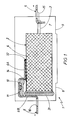
- FIG. 1 represents a tantalum capacitor 1 comprising a capacitor body 2 vis-à-vis which an tantalum anode rod 3 protrudes.
- This capacitor body 2 is of any known type suitable with a porous core of oxidized tantalum superficially, coated in a solid electrolyte formed of manganese dioxide and partially covered with various suitable layers including an outer layer of counter electrode 4 electrically insulated from the anode rod 3.
- a positive connection conductive tab 5 is fixed to the anode rod 3 (by means of a cut 5A advantageously provided) while a negative connection conductive tab 6 is fixed to the counter electrode layer 4.
- the conductive tab 6 is formed of two electrically insulated sections 6A and 6B, except that a calibrated fusible wire 10 is fixed at its ends, for example by soldering to each of these sections, with the formation of solder zones 11.
- This fusible wire 10 is of any suitable type; it is for example a yarn sold under the brand "PYROFUSE" by the company PYROFUSE CORPORATION. It may be an aluminum wire covered with a palladium or copper film, or a lead-tin-silver wire, or lead-silver wire in known suitable proportions.
- the sections 6A and 6B have parallel tabs 12 and 13, respectively, between which a space of predetermined constant width is provided (see FIG. 3) which determines the effective length of the fusible wire 10.
- This wire 10 is embedded in a protective resin 14 which also adheres to the legs 12 and 13, here filling a cavity formed between parallel portions of the sections 6A and 6B.
- This protective resin 14 plays two roles: . thermal protection of the insulating resin constituting the block 7 in the event of melting of the fusible wire under the effect of an exaggerated intensity; this allows a precise definition of the melting characteristics (approximately 400 ° C or even up to 660 ° C depending on the nature of the materials constituting the fusible wire).
- this protective resin 14 is chosen so as not to undergo carbonization at the melting temperature of the fusible wire, so as not to introduce residual resistance; . mechanical bonding of legs 6 and 7 (see below) thanks to its rigidity; this resin 14 therefore constitutes a support and connection mass for the sections 6A and 6B.
- This protective resin rigid and thermally insulating, non-carbonizable at the melting temperature of fuse 10, is for example a resin of the CHIPBONDER 360 or LID 1043 type.
- This resin can also be similar to the constituent resin of block 7, it being specified that, being formed before said block (see below), it has an interface in the finished capacitor 1 which makes it possible to detect its existence.
- Holes 15 and 16 are advantageously provided in the tongues 6 and 7 to improve the anchoring of these in the block 7.
- FIGS. 2 and 3 illustrate two successive stages in the manufacture of the capacitor 1, chosen so as to show the detail of the formation of the tongues 6 and 7 and of the fixing of the fusible wire 10.
- FIG. 2 shows a portion of a plate 100 of electrically conductive material (for example of iron-nickel alloy of the FN 42 type) in which various cuts have been made (hatched areas with spaced hatching), for example by stamping.
- electrically conductive material for example of iron-nickel alloy of the FN 42 type
- This perforated conductive plate (in English “lead frame”) here comprises two vertical strips 20 and 21 secured to two horizontal strips 22 and 23 having holes 24 and 25 for positioning. This arrangement is reproduced identically periodically along the horizontal bands.
- the strip 26 comprises, from the horizontal strip 20, a section 26A intended to constitute the section 6B of the tongue 6, in which the bore 16 is formed and terminated along one of its flanks by the tab 13 which here has a width close to a third of that of the strip 26.
- This strip 26 then comprises a section 26B connected by a T-shaped strip 28 to the horizontal strip 20 and intended to become the section 6A of the tongue 6.
- the section 26B is extended on one of its flanks, away from the tab 13 by a tab corresponding to the tab 12 of the section 6A (here the same width as the tab 13).
- This strip 26 finally comprises a section 26C connected to the horizontal strip 21, intended to constitute the tab 5 of the capacitor 1 and in which the bore 15 and the notch 5A of the section 5 are formed.
- the strip 27 has similar sections 27A, 27B, and 27C, the section 27B being connected to the horizontal strip 20 by said strip 28 in T.
- the dimensioning of the T-band 28 is chosen so as to ensure by itself a rigid mechanical connection between the middle sections 26B and 27B to the horizontal band 20.
- the perforated plate 100 is then folded along the fold lines A, B, C, D and E so as to give the sections of the strips 26 and 27 the desired configuration for the tongues 6 and 7 (with the formation of a sort of cavity intended to receive the mass-support 14).
- the fold lines are shown in FIG. 3.
- the folding of these bands 26 and 27 is also applied to the T-band 28 but, in the example considered, is not applied to the bands 22 and 23 which thus define, with the horizontal bands 20 and 21 a reference plane.
- Fixing is then carried out by soldering the calibrated fuse wire 10 which here extends over the entire width of the strip 26 (or 27). As the sections 26A and 26B are held in relative position by the strip 28, the transverse spacing between the legs 12 and 13 remains constant, equal to their spacing in the flat configuration of FIG. 2, while their sides are coplanar as in Figure 2.
- the protective resin 14 is then applied (in the aforementioned cavity) which, due to its rigidity after polymerization, can alone ensure the mechanical joining of the sections 26A and 26B (27A and 27B).
- the protective resin 14 is advantageously of a type suitable for polymerizing under ultraviolet radiation. It is advantageously a resin of the CHIPBONDER 360 or LID 1043 type.
- a capacitor body 4 is also prepared, of which the edge (generally silver) opposite the anode rod 3 is advantageously coated with a layer 31 of insulating resin of any suitable known type so as to avoid any short circuit between this edge and the vertical part of the section 6B of the tongue 6. As a variant, this insulating resin is directly applied to said vertical part of the section 6B.
- the capacitor body 4 is then positioned near the sections 6A, 6B and 5; the horizontal part of the section 6A is glued to the body 4, in practice with silver glue 32, while the tongue 5 is welded to the tantalum wire 3.
- capacitor body + tabs 6A, 6B, 5 between the parts of a mold using the strips 20 to 23 for positioning purposes.
- the resin 7 is injected and after polymerization thereof (in practice under temperature) the capacitor is released from the mold.
- This molding operation is carried out for each pair of strips 26/27 delimited by cutting from the plate 100.
- the fusible element can be provided in the positive tab; it can be placed at the end of the capacitor body and not on one side.
Landscapes
- Engineering & Computer Science (AREA)
- Power Engineering (AREA)
- Microelectronics & Electronic Packaging (AREA)
- Fixed Capacitors And Capacitor Manufacturing Machines (AREA)
- Fuses (AREA)
Applications Claiming Priority (2)
| Application Number | Priority Date | Filing Date | Title |
|---|---|---|---|
| FR8809015A FR2633770B1 (fr) | 1988-07-04 | 1988-07-04 | Condensateur a electrolyte solide, notamment au tantale, a fusible incorpore |
| FR8809015 | 1988-07-04 |
Publications (2)
| Publication Number | Publication Date |
|---|---|
| EP0350366A1 true EP0350366A1 (de) | 1990-01-10 |
| EP0350366B1 EP0350366B1 (de) | 1993-09-08 |
Family
ID=9368030
Family Applications (1)
| Application Number | Title | Priority Date | Filing Date |
|---|---|---|---|
| EP89401808A Expired - Lifetime EP0350366B1 (de) | 1988-07-04 | 1989-06-26 | Festelektrolytkondensator, insbesondere aus Tantal, mit einer eingebauten Schmelzsicherung |
Country Status (6)
| Country | Link |
|---|---|
| US (1) | US4899258A (de) |
| EP (1) | EP0350366B1 (de) |
| JP (1) | JPH0265116A (de) |
| DE (1) | DE68908976T2 (de) |
| ES (1) | ES2044169T3 (de) |
| FR (1) | FR2633770B1 (de) |
Cited By (5)
| Publication number | Priority date | Publication date | Assignee | Title |
|---|---|---|---|---|
| EP0434489A1 (de) * | 1989-12-19 | 1991-06-26 | Sprague France | Festelektrolytkondensator, insbesondere aus Tantal, mit kontrollierbarer eingebauter Schmelzsicherung |
| EP0459873A1 (de) * | 1990-05-29 | 1991-12-04 | Sprague France | Festelektrolytkondensator, insbesondere aus Tantal, mit gestanzter eingebauter Schmelzsicherung und Verfahren zu seiner Herstellung |
| EP0499109A1 (de) * | 1991-02-15 | 1992-08-19 | Nec Corporation | Festelektrolytkondensator in Chip-Bauweise mit Sicherungselement und Verfaren zu seiner Herstellung |
| EP0519330A1 (de) * | 1991-06-19 | 1992-12-23 | Nec Corporation | Festelektrolytkondensator in Chipbauweise mit Schmelzsicherung |
| EP0418562B1 (de) * | 1989-09-19 | 1995-03-29 | Siemens Aktiengesellschaft | Verfahren zum Herstellen eines Festelektrolytkondensators in Chip-Bauweise mit Sicherungselement |
Families Citing this family (7)
| Publication number | Priority date | Publication date | Assignee | Title |
|---|---|---|---|---|
| US4989119A (en) * | 1988-07-04 | 1991-01-29 | Sprague Electric Company | Solid electrolyte capacitor with testable fuze |
| US5057973A (en) * | 1988-07-04 | 1991-10-15 | Sprague Electric Company | Solid electrolyte capacitor with integral stamped fuze |
| JPH04246813A (ja) * | 1991-02-01 | 1992-09-02 | Nec Corp | ヒューズ入り固体電解コンデンサ |
| JP2785543B2 (ja) * | 1991-10-03 | 1998-08-13 | 日本電気株式会社 | ヒューズ付きチップ状固体電解コンデンサ |
| US5357399A (en) * | 1992-09-25 | 1994-10-18 | Avx Corporation | Mass production method for the manufacture of surface mount solid state capacitor and resulting capacitor |
| US8717777B2 (en) | 2005-11-17 | 2014-05-06 | Avx Corporation | Electrolytic capacitor with a thin film fuse |
| US7532457B2 (en) * | 2007-01-15 | 2009-05-12 | Avx Corporation | Fused electrolytic capacitor assembly |
Citations (3)
| Publication number | Priority date | Publication date | Assignee | Title |
|---|---|---|---|---|
| DE744480C (de) * | 1936-08-06 | 1944-02-26 | Dielektra Ag | Kondensatoranordnung, bestehend aus einer Reihe uebereinanderliegender und in einem Traenkmittel angeordneter Flachwickel |
| EP0232868A2 (de) * | 1986-02-07 | 1987-08-19 | Nec Corporation | Festelektrolytkondensator mit Schmelzsicherung |
| EP0233751A2 (de) * | 1986-02-15 | 1987-08-26 | Avx Limited | Schmelzsicherung für ein elektronisches Bauelement |
Family Cites Families (5)
| Publication number | Priority date | Publication date | Assignee | Title |
|---|---|---|---|---|
| US4107762A (en) * | 1977-05-16 | 1978-08-15 | Sprague Electric Company | Solid electrolyte capacitor package with an exothermically-alloyable fuse |
| US4224656A (en) * | 1978-12-04 | 1980-09-23 | Union Carbide Corporation | Fused electrolytic capacitor assembly |
| JPS6027177B2 (ja) * | 1980-04-02 | 1985-06-27 | 松下電器産業株式会社 | チップ状固体電解コンデンサおよびその製造方法 |
| US4514468A (en) * | 1983-05-26 | 1985-04-30 | Sprague Electric Company | Electronic component with UV-cured coating |
| US4660127A (en) * | 1985-12-17 | 1987-04-21 | North American Philips Corporation | Fail-safe lead configuration for polar SMD components |
-
1988
- 1988-07-04 FR FR8809015A patent/FR2633770B1/fr not_active Expired - Fee Related
-
1989
- 1989-03-16 US US07/324,131 patent/US4899258A/en not_active Expired - Fee Related
- 1989-06-26 ES ES89401808T patent/ES2044169T3/es not_active Expired - Lifetime
- 1989-06-26 EP EP89401808A patent/EP0350366B1/de not_active Expired - Lifetime
- 1989-06-26 DE DE89401808T patent/DE68908976T2/de not_active Expired - Fee Related
- 1989-07-04 JP JP1171339A patent/JPH0265116A/ja active Pending
Patent Citations (3)
| Publication number | Priority date | Publication date | Assignee | Title |
|---|---|---|---|---|
| DE744480C (de) * | 1936-08-06 | 1944-02-26 | Dielektra Ag | Kondensatoranordnung, bestehend aus einer Reihe uebereinanderliegender und in einem Traenkmittel angeordneter Flachwickel |
| EP0232868A2 (de) * | 1986-02-07 | 1987-08-19 | Nec Corporation | Festelektrolytkondensator mit Schmelzsicherung |
| EP0233751A2 (de) * | 1986-02-15 | 1987-08-26 | Avx Limited | Schmelzsicherung für ein elektronisches Bauelement |
Non-Patent Citations (1)
| Title |
|---|
| IBM TECHNICAL DISCLOSURE BULLETIN, vol. 27, no. 4A, septembre 1984, pages 2026-2027, New York, US; R.E. HORSTMANN et al.: "Current-limited chip capacitor" * |
Cited By (7)
| Publication number | Priority date | Publication date | Assignee | Title |
|---|---|---|---|---|
| EP0418562B1 (de) * | 1989-09-19 | 1995-03-29 | Siemens Aktiengesellschaft | Verfahren zum Herstellen eines Festelektrolytkondensators in Chip-Bauweise mit Sicherungselement |
| EP0434489A1 (de) * | 1989-12-19 | 1991-06-26 | Sprague France | Festelektrolytkondensator, insbesondere aus Tantal, mit kontrollierbarer eingebauter Schmelzsicherung |
| EP0459873A1 (de) * | 1990-05-29 | 1991-12-04 | Sprague France | Festelektrolytkondensator, insbesondere aus Tantal, mit gestanzter eingebauter Schmelzsicherung und Verfahren zu seiner Herstellung |
| FR2662847A1 (fr) * | 1990-05-29 | 1991-12-06 | Sprague France | Condensateur a electrolyte solide, notamment au tantale, a fusible incorpore estampe. |
| EP0499109A1 (de) * | 1991-02-15 | 1992-08-19 | Nec Corporation | Festelektrolytkondensator in Chip-Bauweise mit Sicherungselement und Verfaren zu seiner Herstellung |
| US5216584A (en) * | 1991-02-15 | 1993-06-01 | Nec Corporation | Fused chip-type solid electrolytic capacitor and method of manufacturing the same |
| EP0519330A1 (de) * | 1991-06-19 | 1992-12-23 | Nec Corporation | Festelektrolytkondensator in Chipbauweise mit Schmelzsicherung |
Also Published As
| Publication number | Publication date |
|---|---|
| ES2044169T3 (es) | 1994-01-01 |
| DE68908976T2 (de) | 1994-05-05 |
| US4899258A (en) | 1990-02-06 |
| JPH0265116A (ja) | 1990-03-05 |
| DE68908976D1 (de) | 1993-10-14 |
| FR2633770B1 (fr) | 1991-05-31 |
| EP0350366B1 (de) | 1993-09-08 |
| FR2633770A1 (fr) | 1990-01-05 |
Similar Documents
| Publication | Publication Date | Title |
|---|---|---|
| EP0350366B1 (de) | Festelektrolytkondensator, insbesondere aus Tantal, mit einer eingebauten Schmelzsicherung | |
| EP0283414B1 (de) | Sicherung mit Umhüllung aus fester Keramik hoher Dichte und Herstellungsverfahren dieser Sicherung | |
| FR2576150A1 (fr) | Batterie d'accumulation a faible encombrement et a systeme de raccordement perfectionne | |
| EP0916144B1 (de) | Herstellungsverfahren für eine transponderspule | |
| FR2691563A1 (fr) | Carte comprenant au moins un élément électronique et procédé de fabrication d'une telle carte. | |
| EP0500168A1 (de) | Verfahren zur Herstellung eines elektronischen Moduls für eine Speicherkarte und elektronisches, nach diesem Verfahren hergestelltes Modul | |
| EP0650620A1 (de) | Verfahren zur herstellung einer karte, die mindestens einen elektronischen baustein enthält,und nach einen solchen verfahren hergestellte karte. | |
| EP1141887B1 (de) | Verfahren zur herstellung einer kontaktlosen chipkarte | |
| EP0658945B1 (de) | Elektrodeplatte mit schaumförmigem Träger für elektrochemische Generatoren und Verfahren zur Herstellung einer solchen Elektrode | |
| FR2625602A1 (fr) | Procede de fabrication de condensateurs electrolytiques a l'aluminium et condensateur a anode integree obtenu par ce procede | |
| FR2725304A1 (fr) | Fusible pour microplaquette | |
| EP0434489B1 (de) | Festelektrolytkondensator, insbesondere aus Tantal, mit kontrollierbarer eingebauter Schmelzsicherung | |
| EP0375505A1 (de) | Elektrisches Bauelement mit direktem Übertrag | |
| EP0459873B1 (de) | Festelektrolytkondensator, insbesondere aus Tantal, mit gestanzter eingebauter Schmelzsicherung und Verfahren zu seiner Herstellung | |
| EP0641469A1 (de) | Verfahren zur herstellung einer kante, die mindestenseinen elektronischen baustein enthält | |
| EP0246134B1 (de) | Präzisionskondensator zur Einstellung der Nennkapazität | |
| EP0120754B1 (de) | Polarisierte elektronische Vorrichtung und Verfahren zu ihrer Herstellung | |
| FR2674676A1 (fr) | Condensateur a electrolyte solide. | |
| EP4584804B1 (de) | Sicherung | |
| FR2536901A1 (fr) | Condensateur multi-couches de puissance | |
| EP0227527B1 (de) | Verfahren zur Herstellung eines Festelektrolyt-Tantalkondensators ohne Anschlussdraht oder -band sowie eine Herstellungsvorrichtung und ein so hergestellter Kondensator | |
| FR2646011A1 (fr) | Structure capacitive perfectionnee | |
| EP0543728B1 (de) | Festelektrolytkondensator mit kontrollierbarer Polarität und diesen enthaltendes Schaltungselement | |
| EP2775492B1 (de) | Kapazitives Element, das einen Separator mit Protuberanzen umfasst, die sein Herausziehen verhindern | |
| FR2782411A1 (fr) | Condensateur modulaire autoprotege |
Legal Events
| Date | Code | Title | Description |
|---|---|---|---|
| PUAI | Public reference made under article 153(3) epc to a published international application that has entered the european phase |
Free format text: ORIGINAL CODE: 0009012 |
|
| AK | Designated contracting states |
Kind code of ref document: A1 Designated state(s): DE ES GB IT |
|
| 17P | Request for examination filed |
Effective date: 19900208 |
|
| 17Q | First examination report despatched |
Effective date: 19921110 |
|
| ITF | It: translation for a ep patent filed | ||
| GRAA | (expected) grant |
Free format text: ORIGINAL CODE: 0009210 |
|
| AK | Designated contracting states |
Kind code of ref document: B1 Designated state(s): DE ES GB IT |
|
| REF | Corresponds to: |
Ref document number: 68908976 Country of ref document: DE Date of ref document: 19931014 |
|
| GBT | Gb: translation of ep patent filed (gb section 77(6)(a)/1977) |
Effective date: 19930922 |
|
| REG | Reference to a national code |
Ref country code: ES Ref legal event code: FG2A Ref document number: 2044169 Country of ref document: ES Kind code of ref document: T3 |
|
| PLBE | No opposition filed within time limit |
Free format text: ORIGINAL CODE: 0009261 |
|
| STAA | Information on the status of an ep patent application or granted ep patent |
Free format text: STATUS: NO OPPOSITION FILED WITHIN TIME LIMIT |
|
| 26N | No opposition filed | ||
| PGFP | Annual fee paid to national office [announced via postgrant information from national office to epo] |
Ref country code: GB Payment date: 19960617 Year of fee payment: 8 |
|
| PGFP | Annual fee paid to national office [announced via postgrant information from national office to epo] |
Ref country code: DE Payment date: 19960619 Year of fee payment: 8 |
|
| PGFP | Annual fee paid to national office [announced via postgrant information from national office to epo] |
Ref country code: ES Payment date: 19960627 Year of fee payment: 8 |
|
| PG25 | Lapsed in a contracting state [announced via postgrant information from national office to epo] |
Ref country code: GB Free format text: LAPSE BECAUSE OF NON-PAYMENT OF DUE FEES Effective date: 19970626 |
|
| PG25 | Lapsed in a contracting state [announced via postgrant information from national office to epo] |
Ref country code: ES Free format text: LAPSE BECAUSE OF NON-PAYMENT OF DUE FEES Effective date: 19970627 |
|
| GBPC | Gb: european patent ceased through non-payment of renewal fee |
Effective date: 19970626 |
|
| PG25 | Lapsed in a contracting state [announced via postgrant information from national office to epo] |
Ref country code: DE Free format text: LAPSE BECAUSE OF NON-PAYMENT OF DUE FEES Effective date: 19980303 |
|
| REG | Reference to a national code |
Ref country code: ES Ref legal event code: FD2A Effective date: 19980711 |
|
| PG25 | Lapsed in a contracting state [announced via postgrant information from national office to epo] |
Ref country code: IT Free format text: LAPSE BECAUSE OF NON-PAYMENT OF DUE FEES;WARNING: LAPSES OF ITALIAN PATENTS WITH EFFECTIVE DATE BEFORE 2007 MAY HAVE OCCURRED AT ANY TIME BEFORE 2007. THE CORRECT EFFECTIVE DATE MAY BE DIFFERENT FROM THE ONE RECORDED. Effective date: 20050626 |