EP0350964A2 - Mécanisme pour marteaux d'impression - Google Patents
Mécanisme pour marteaux d'impression Download PDFInfo
- Publication number
- EP0350964A2 EP0350964A2 EP89112995A EP89112995A EP0350964A2 EP 0350964 A2 EP0350964 A2 EP 0350964A2 EP 89112995 A EP89112995 A EP 89112995A EP 89112995 A EP89112995 A EP 89112995A EP 0350964 A2 EP0350964 A2 EP 0350964A2
- Authority
- EP
- European Patent Office
- Prior art keywords
- hammer
- armatures
- armature
- mechanism according
- return
- Prior art date
- Legal status (The legal status is an assumption and is not a legal conclusion. Google has not performed a legal analysis and makes no representation as to the accuracy of the status listed.)
- Withdrawn
Links
- 230000007246 mechanism Effects 0.000 title claims abstract description 47
- 230000003116 impacting effect Effects 0.000 claims description 6
- 230000002452 interceptive effect Effects 0.000 claims description 2
- 230000009977 dual effect Effects 0.000 abstract 1
- 230000001133 acceleration Effects 0.000 description 4
- 210000005069 ears Anatomy 0.000 description 4
- 230000000694 effects Effects 0.000 description 3
- 239000000696 magnetic material Substances 0.000 description 3
- 241000723353 Chrysanthemum Species 0.000 description 2
- 235000005633 Chrysanthemum balsamita Nutrition 0.000 description 2
- 210000003739 neck Anatomy 0.000 description 2
- 230000008878 coupling Effects 0.000 description 1
- 238000010168 coupling process Methods 0.000 description 1
- 238000005859 coupling reaction Methods 0.000 description 1
- 230000005672 electromagnetic field Effects 0.000 description 1
- 230000004907 flux Effects 0.000 description 1
- 239000000463 material Substances 0.000 description 1
- 230000004048 modification Effects 0.000 description 1
- 238000012986 modification Methods 0.000 description 1
- 239000004033 plastic Substances 0.000 description 1
- 239000004417 polycarbonate Substances 0.000 description 1
- 229920000515 polycarbonate Polymers 0.000 description 1
Images

Classifications
-
- B—PERFORMING OPERATIONS; TRANSPORTING
- B41—PRINTING; LINING MACHINES; TYPEWRITERS; STAMPS
- B41J—TYPEWRITERS; SELECTIVE PRINTING MECHANISMS, i.e. MECHANISMS PRINTING OTHERWISE THAN FROM A FORME; CORRECTION OF TYPOGRAPHICAL ERRORS
- B41J9/00—Hammer-impression mechanisms
- B41J9/02—Hammers; Arrangements thereof
- B41J9/10—Hammers; Arrangements thereof of more than one hammer, e.g. one for each character position
- B41J9/12—Hammers; Arrangements thereof of more than one hammer, e.g. one for each character position each operating in more than one character position
-
- B—PERFORMING OPERATIONS; TRANSPORTING
- B41—PRINTING; LINING MACHINES; TYPEWRITERS; STAMPS
- B41J—TYPEWRITERS; SELECTIVE PRINTING MECHANISMS, i.e. MECHANISMS PRINTING OTHERWISE THAN FROM A FORME; CORRECTION OF TYPOGRAPHICAL ERRORS
- B41J9/00—Hammer-impression mechanisms
- B41J9/02—Hammers; Arrangements thereof
- B41J9/127—Mounting of hammers
-
- B—PERFORMING OPERATIONS; TRANSPORTING
- B41—PRINTING; LINING MACHINES; TYPEWRITERS; STAMPS
- B41J—TYPEWRITERS; SELECTIVE PRINTING MECHANISMS, i.e. MECHANISMS PRINTING OTHERWISE THAN FROM A FORME; CORRECTION OF TYPOGRAPHICAL ERRORS
- B41J9/00—Hammer-impression mechanisms
- B41J9/16—Means for cocking or resetting hammers
- B41J9/24—Electromagnetic means
-
- B—PERFORMING OPERATIONS; TRANSPORTING
- B41—PRINTING; LINING MACHINES; TYPEWRITERS; STAMPS
- B41J—TYPEWRITERS; SELECTIVE PRINTING MECHANISMS, i.e. MECHANISMS PRINTING OTHERWISE THAN FROM A FORME; CORRECTION OF TYPOGRAPHICAL ERRORS
- B41J9/00—Hammer-impression mechanisms
- B41J9/26—Means for operating hammers to effect impression
- B41J9/38—Electromagnetic means
Definitions
- the present invention relates to print hammer mechanisms, and particularly to an improved assembly including a print hammer and actuators for driving the hammer into impacting relationship with a printing element for printing on a record medium and also for driving the hammer in an opposite or return direction clear of the printing element so as to allow different printing elements to move into printing position, minimizing the time required for the stroke of the hammer from the forward and return directions so as to increase printing speed.
- the invention is especially suitable for use in band printers in which a band carries the printing elements so as to present different elements for impact by the hammer or hammers of a print hammer mechanism.
- the invention may also be used in other printers utilizing printing elements such as daisy wheel, thimble or ball-type elements.
- actuators which drive the hammer in both the forward and return direction.
- Such actuators have direct coupling between the electromagnetic field structure and the hammer. They are subject to hysteresis effects which increase the time required to accelerate the hammer and the linkage attached thereto between the forward and return portion of the stroke thereby limiting the speed of the printing element carrier such as the band, daisy wheel or the like, and reducing overall printing speed.
- a print hammer mechanism in accordance with the invention uses a print hammer which is moveable toward and away from a printing position.
- the hammer is driven by first and second armatures which are independently moveable and disposed for engagement with the hammer to drive the hammer in the forward and return direction.
- the armatures are mounted in non-interfering relationship with the hammer until engagement therewith. This enables the armatures to accelerate through a sufficient distance prior to contacting the hammer which minimizes the time for execution of the forward and return strokes.
- the armatures and the hammer may be biased by weak return springs to a home position.
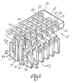
- FIGS. 1 and 2 there shown the platen 11, record medium paper 12, ribbon 38 and printing element 20 of the print band of a band printer which incorporates a print hammer mechanism 10 embodying the invention.
- the mechanism 10 has a plurality of bars which provide the hammers 50 thereof. While six hammers 50 are shown, it will be understood that the mechanism 10 may have one or more hammers.
- a hammer housing 52 supports the hammers 50 in slots 53 therein for reciprocating motion therein.
- the forward ends of the slots 53 which face the printing elements 20 are open so that the hammers can project therethrough.
- the slots 53 have rear wall surfaces 55 which index, and define the home position of, the hammers at the end of the return stroke in a direction away from the printing elements 20.
- the hammer housing 52 has a slot 58 which is perpendicular to the slots 53 in which the hammers 50 are mounted. There is another slot 59 in the housing 52 which is parallel to the slot 58 and provides access to the end surface 55 which indexes the hammers 50 and their return position.
- the hammers 50 have a neck 60 of reduced height and of a length approximately equal to the length (in the direction of hammer travel) of the forward slot 58.
- Springs 56 are located around the necks 60 in the slot 58. The ends of the springs bear against forward and rear walls 61 and 62 of the slot 58. The springs 56 bias the hammers 50 against the home position indexing surface 55.
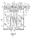
- the assembly of the hammers 50 and housing 52 are disposed on a support body 65 (shown in FIG. 2 but not shown in FIG. 1 to simplify the illustration).
- This body 65 provides a mounting for a plurality of spaced magnet structures or cores 86 and 87, one of which is provided for each of the hammers.
- These cores have pole pieces 89 and 90 around which coils 88 and 89 are wound.
- These coils are connected to sources of drive current which preferably provide pulses of current in timed relationship for actuating the hammers 50.
- the cores 86 and 87 and the coils 89 and 90 provide magnetic actuating means for actuating armatures 70 and 71.
- Armature 70 will be referred to as the print armature and the armature 71 as the return armature.
- Each armature is pivotly mounted on an axis 74 and 75 which extends perpendicular to the path of travel of the hammers 50.
- the armatures are preferably bars having magnetic material, at least in the sections thereof facing the ends 93 and 95 of the poles 90.
- the pivotal mounting is, by pins to ears 97 and 98 which project toward each other from the cores 86 and 87 near the bottom of the cores.
- the pins extend from the armatures 70 and 71 into holes in the cores. Other pivotal connections can be used.
- the pins may extend between pairs of ears 99 and 100 on each of the armatures 70 and 71 which overlap the ears 97 and 98 on the cores 86 and 87 and capture the ears 97 and 98 when pinned thereto.
- the armatures 70 and 71 may be made of light weight plastic material, such as polycarbonate, with inserts 84 and 85 of magnetic material which complete a magnetic circuit between the pole ends 93 and 95 and the rest of the cores 86 and 87.
- the slots 53 in the hammer housing 52 and therefore the spacing of the hammers from each other may be equal to or slightly wider than the width of the armatures 70 and 71.
- the armatures having a width much larger the width of the hammers 50.
- the assembly of hammer housing 52 and hammers 50 may be moveable in a direction along the path of the band carrying the printing elements 22 (perpendicular to the direction of travel of the hammers 50) so as to enable printing of dot elements as well as characters.
- a translating mechanism such as a belt connected to the housing 52 may be used. Such a translating mechanism is described in the above-referenced Patent 4,736,679.
- the housing 52 may be connected to the support body 65 or be an integral part thereof.
- the hammers 50 have slots 102 with end walls 103 and 105 which provide impact surfaces for the print armature 70 and the return armature 71, respectively.
- the armature 70 and 71 extend into the slots 102 and their upper ends are in the slots.
- a stop bar 80 which is connected to the support body 65 at the ends thereof provides a rest or home position for the armatures.
- Springs 78 and 79 bias the armatures (rotate them around their axes 74 and 75) against the stop 80.
- the armatures When disposed against the stop 80, the armatures are decoupled from the hammers because there is free space between the armatures and the impact surfaces 103 and 105. Therefore, the hammers 50 are free to move without interference and are restrained only by the basis of the return spring 56.
- the relative dimensions of the armature ends and the location of the print armature impact surface 76 and the return armature impact surface 77 to the surfaces 103 and 105 provides for freedom of movement of the hammer with respect to armatures over the working distance of the hammer which is its total travel in the forward direction to a position where the hammers impact the printing elements 20 plus a distance to accommodate acceleration in the forward or print direction and bounce off the printing elements 20, ribbon 38 and paper 12 when traveling in the return direction.
- the return spring 78 and 79 as well as the hammer return spring 56 are very weak springs which serve merely to maintain the hammer and armature against the stop 80 and end surface 55 between actuations.
- the distances (spacing) between the impacting surfaces 76 and 103 and 77 and 105 enable the acceleration of the armatures to develop speed and force sufficient to drive the hammer in the forward direction for printing and then in the return direction in time sequence.
- the mass of the armatures 70 and 71 is in each case much greater than the mass of the hammers 50 which they impact.
- the springs are weak. Therefore, acceleration is rapid and the time for movement of the hammers into impacting relationship with the printing elements is minimized.
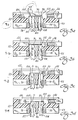
- FIGS. 3A through 3H shows the mechanism in positions during a cycle at successive intervals of time indicated as T1 through T8.
- the start or relaxed position prior to a print and return cycle, at time T0 is shown in FIG. 2.
- T0 the mechanism is at rest and a current pulse to command a print operation is applied to the new print coil 88.
- the magnetic flux is building up in the core, but the magnetic force is not sufficient to attract the print armature 70 and the position of the components is not changed.
- T2 being shown in FIG. 3B
- the print hammer has accelerated to a position where contact is made between the surfaces 76 and 103.
- the hammer 50 then begins its driven flight in the forward direction.
- the print armature 70 continues to drive the hammer in the forward direction until the armature contacts a stop indicated at 108 which is part of the support body 65. Contact with the stop occurs at time T3 as shown in FIG. 3C.
- the return pulse of current is applied, before the termination of the forward pulse, to the return coil 89, and the return armature 71 begins moving away from the stop 80.
- the hammer continues its acceleration in the forward direction and begins its ballistic flight, unimpeded by the print armature (since the print armature is against the stop 108) into impact relationship with the printing element.
- the printing element is being driven into the platen and presses the ribbon 38 and the paper 12 against the platen to actually print the character.
- the return armature 71 contacts the hammer at the impact surface 105 and begins the driven flight of the hammer towards the home position. The hammer leaves the path of the printing element and the print band can move to the next character position.
- the entire cycle in a typical print hammer mechanism may be performed within 8 milliseconds.
- the period of time during which the hammer is in the path of the printing element such that the printing element should be stationery is less than 2 milliseconds (i.e., from T3 to T5).
- the time intervals mentioned are exemplary and depend upon the mass of the elements, actuating currents and may increased or reduced to accommodate particular printer designs.
Landscapes
- Physics & Mathematics (AREA)
- Electromagnetism (AREA)
- Impact Printers (AREA)
Applications Claiming Priority (2)
| Application Number | Priority Date | Filing Date | Title |
|---|---|---|---|
| US219494 | 1988-07-14 | ||
| US07/219,494 US4852481A (en) | 1988-07-14 | 1988-07-14 | Print hammer mechanism |
Publications (2)
| Publication Number | Publication Date |
|---|---|
| EP0350964A2 true EP0350964A2 (fr) | 1990-01-17 |
| EP0350964A3 EP0350964A3 (fr) | 1990-06-27 |
Family
ID=22819492
Family Applications (1)
| Application Number | Title | Priority Date | Filing Date |
|---|---|---|---|
| EP89112995A Withdrawn EP0350964A3 (fr) | 1988-07-14 | 1989-07-14 | Mécanisme pour marteaux d'impression |
Country Status (3)
| Country | Link |
|---|---|
| US (1) | US4852481A (fr) |
| EP (1) | EP0350964A3 (fr) |
| JP (1) | JPH02131961A (fr) |
Families Citing this family (3)
| Publication number | Priority date | Publication date | Assignee | Title |
|---|---|---|---|---|
| US5150976A (en) * | 1987-05-08 | 1992-09-29 | Siemens-Nixdorf Informationssysteme Ag | Matrix printing head with forward and return articulated-armature magnets |
| JPS6446235U (fr) * | 1987-05-11 | 1989-03-22 | ||
| US5906157A (en) * | 1998-05-06 | 1999-05-25 | Banctec, Inc. | High speed impact print hammer |
Family Cites Families (18)
| Publication number | Priority date | Publication date | Assignee | Title |
|---|---|---|---|---|
| DE1237816B (de) * | 1963-08-24 | 1967-03-30 | Ibm Deutschland | Druckhammerantrieb fuer Schnelldrucker |
| US3266419A (en) * | 1964-08-11 | 1966-08-16 | Navigation Computer Corp | High speed impact print hammer assembly with resilient energy storing means |
| US3477365A (en) * | 1966-07-22 | 1969-11-11 | Mohawk Data Sciences Corp | Hysteresis drive for high speed print hammers |
| US3543906A (en) * | 1967-08-21 | 1970-12-01 | Edward J Buxton | Solenoid controlled printing hammer mechanism |
| US3504623A (en) * | 1968-04-03 | 1970-04-07 | Itt | Hammer arrangement for high-speed printers |
| US3705370A (en) * | 1971-04-15 | 1972-12-05 | Ibm | Magnetically actuated and restored print hammer |
| US3741113A (en) * | 1971-06-25 | 1973-06-26 | Ibm | High energy print hammer unit with fast settle out |
| FR2153627A5 (fr) * | 1971-09-17 | 1973-05-04 | Honeywell Bull | |
| US4121518A (en) * | 1976-10-12 | 1978-10-24 | Documation Incorporated | High speed printer hammer assembly |
| DE2907456A1 (de) * | 1979-02-26 | 1980-09-04 | Olympia Werke Ag | Druckhammeranordnung an schreib- o.ae. daten schreibenden bueromaschinen mit einem summentypentraeger |
| DE3018407A1 (de) * | 1980-05-14 | 1981-11-19 | Ibm Deutschland Gmbh, 7000 Stuttgart | Elektromagnetisch betaetigbarer stoesselantrieb, insbesondere fuer anschlagdrucker |
| US4440079A (en) * | 1982-01-11 | 1984-04-03 | International Business Machines Corporation | Control system for timing hammers of impact printers |
| JPS59123678A (ja) * | 1982-12-29 | 1984-07-17 | インタ−ナショナル ビジネス マシ−ンズ コ−ポレ−ション | 印刷アクチユエ−タ |
| US4522122A (en) * | 1983-05-03 | 1985-06-11 | Ncr Canada Ltd - Ncr Canada Ltee | Fast impact hammer for high speed printer |
| US4523867A (en) * | 1983-07-25 | 1985-06-18 | Genicom Corporation | Bi-directional drive print wire actuator with forward-velocity and reverse-position closed loop feedback control |
| JPS60109860A (ja) * | 1983-11-18 | 1985-06-15 | Toshiba Corp | プリンタの印字ハンマ |
| US4687354A (en) * | 1985-09-12 | 1987-08-18 | Kazumi Tanaka | Dot matrix printer head |
| US4736679A (en) * | 1987-04-22 | 1988-04-12 | L. James Hubbard | Band printer and print band |
-
1988
- 1988-07-14 US US07/219,494 patent/US4852481A/en not_active Expired - Fee Related
-
1989
- 1989-07-13 JP JP1179188A patent/JPH02131961A/ja active Pending
- 1989-07-14 EP EP89112995A patent/EP0350964A3/fr not_active Withdrawn
Also Published As
| Publication number | Publication date |
|---|---|
| EP0350964A3 (fr) | 1990-06-27 |
| JPH02131961A (ja) | 1990-05-21 |
| US4852481A (en) | 1989-08-01 |
Similar Documents
| Publication | Publication Date | Title |
|---|---|---|
| US3929214A (en) | Wire matrix ballistic impact print head | |
| US3994381A (en) | Wire matrix print head | |
| JPS6213804Y2 (fr) | ||
| US3139820A (en) | Print hammer mechanism | |
| CA1129246A (fr) | Marteau d'imprimante a deux pieces polaires | |
| US5975776A (en) | Dot matrix print head with unitary armature assembly and method of operation thereof | |
| US4852481A (en) | Print hammer mechanism | |
| US4269117A (en) | Electro-magnetic print hammer | |
| US4472072A (en) | Printing apparatus | |
| US3564999A (en) | Print actuation system employing magnetically actuatable hammers and movable type carrier | |
| JPS59115870A (ja) | 印刷ワイヤ・アクチユエ−タ | |
| EP0210636B1 (fr) | Ensemble d'actuateurs électromagnétiques pour les marteaux d'imprimantes à impact | |
| US4496253A (en) | Impact hammer | |
| GB1563779A (en) | Printing apparatus | |
| US4425845A (en) | Bank for accommodating several print ram units | |
| EP0365267B1 (fr) | Tête d'impression pour imprimante par points à impact | |
| US5088844A (en) | Impact dot print head and printer including same | |
| US4664540A (en) | Mechanism utilizing resilient energy | |
| US4839621A (en) | Electromagnetic actuator having improved dampening means | |
| JPS5686773A (en) | Movable coil type printing head | |
| JPS6351148A (ja) | ワイヤ−ドツトプリンタの印字ヘツド | |
| JPS60127167A (ja) | ドットプリンタの印字ヘッド可動装置 | |
| JPH03281356A (ja) | 印字ハンマ | |
| JPS612572A (ja) | ドツトプリンタ印字ヘツド用可動装置 | |
| WO1996039299A1 (fr) | Tete d'imprimante a matrice d'impression par points avec une capacite bidirectionnelle |
Legal Events
| Date | Code | Title | Description |
|---|---|---|---|
| PUAI | Public reference made under article 153(3) epc to a published international application that has entered the european phase |
Free format text: ORIGINAL CODE: 0009012 |
|
| AK | Designated contracting states |
Kind code of ref document: A2 Designated state(s): BE CH DE ES FR GB IT LI NL SE |
|
| PUAL | Search report despatched |
Free format text: ORIGINAL CODE: 0009013 |
|
| RHK1 | Main classification (correction) |
Ipc: B41J 9/38 |
|
| AK | Designated contracting states |
Kind code of ref document: A3 Designated state(s): BE CH DE ES FR GB IT LI NL SE |
|
| STAA | Information on the status of an ep patent application or granted ep patent |
Free format text: STATUS: THE APPLICATION IS DEEMED TO BE WITHDRAWN |
|
| 18D | Application deemed to be withdrawn |
Effective date: 19901228 |