EP0350996B1 - Tragarm mit Gewichtsausgleich für ein Röntgenuntersuchungsgerät - Google Patents
Tragarm mit Gewichtsausgleich für ein Röntgenuntersuchungsgerät Download PDFInfo
- Publication number
- EP0350996B1 EP0350996B1 EP89201776A EP89201776A EP0350996B1 EP 0350996 B1 EP0350996 B1 EP 0350996B1 EP 89201776 A EP89201776 A EP 89201776A EP 89201776 A EP89201776 A EP 89201776A EP 0350996 B1 EP0350996 B1 EP 0350996B1
- Authority
- EP
- European Patent Office
- Prior art keywords
- ray
- ray detector
- support
- examination apparatus
- sleeve
- Prior art date
- Legal status (The legal status is an assumption and is not a legal conclusion. Google has not performed a legal analysis and makes no representation as to the accuracy of the status listed.)
- Expired - Lifetime
Links
Images
Classifications
-
- A—HUMAN NECESSITIES
- A61—MEDICAL OR VETERINARY SCIENCE; HYGIENE
- A61B—DIAGNOSIS; SURGERY; IDENTIFICATION
- A61B6/00—Apparatus or devices for radiation diagnosis; Apparatus or devices for radiation diagnosis combined with radiation therapy equipment
- A61B6/44—Constructional features of apparatus for radiation diagnosis
- A61B6/4429—Constructional features of apparatus for radiation diagnosis related to the mounting of source units and detector units
- A61B6/4435—Constructional features of apparatus for radiation diagnosis related to the mounting of source units and detector units the source unit and the detector unit being coupled by a rigid structure
- A61B6/4441—Constructional features of apparatus for radiation diagnosis related to the mounting of source units and detector units the source unit and the detector unit being coupled by a rigid structure the rigid structure being a C-arm or U-arm
-
- A—HUMAN NECESSITIES
- A61—MEDICAL OR VETERINARY SCIENCE; HYGIENE
- A61B—DIAGNOSIS; SURGERY; IDENTIFICATION
- A61B6/00—Apparatus or devices for radiation diagnosis; Apparatus or devices for radiation diagnosis combined with radiation therapy equipment
- A61B6/44—Constructional features of apparatus for radiation diagnosis
- A61B6/4429—Constructional features of apparatus for radiation diagnosis related to the mounting of source units and detector units
- A61B6/447—Constructional features of apparatus for radiation diagnosis related to the mounting of source units and detector units the source unit or the detector unit being mounted to counterpoise or springs
Definitions
- the invention relates to an X-ray examination apparatus, comprising a vertical column, a sleeve which is connected to the column and which is rotatable about a first horizontal axis, and a C-shaped support which is carried by the sleeve and which is movable in the sleeve about a second axis which intersects the first axis at right angles, said C-shaped support accommodating an X-ray source at a first end and an X-ray detector at a second end, which X-ray detector is movable along a central ray of an X-ray beam to be emitted by the X-ray source.
- an X-ray examination apparatus described therein combined rotation of the X-ray source and the X-ray detector, connected to a two-armed wupport, takes place about three axes which intersect one another at right angles in one point (the iso-centre) which is situated between the X-ray source and the X-ray detector.
- the known X-ray examination apparatus is not balanced and the locking in positions in which the two-armed support is rotated out of a vertical plane about a first horizontal axis is provided by an electric motor and a gearwheel transmission. Movement of the two-armed support in the sleeve under the influence of the force of gravity is prevented by an electric motor which locks the arm in the sleeve for a given irradiation direction.
- the X-ray examination apparatus usually comprises a protection mechanism.
- an X-ray examination apparatus of the kind set forth in accordance with the invention is characterized in that a shift of a centre of gravity of the X-ray detector which occurs upon displacement of the X-ray detector along the central ray is substantially compensated for by way of a counterweight which is secured to the second end of the support and whose direction of movement opposes that of the X-ray detector, in that a common centre of gravity of the support, the X-ray source, the X-ray detector and the counterweight is situated on the second axis for an adjustable range of distances between the X-ray detector and the X-ray source, and in that a common centre of gravity of the sleeve, the support, the X-ray detector, the X-ray source and the counterweight is situated on the first horizontal axis for an adjustable range of distances between the X-ray detector and the X-ray source.
- a two-armed support is formed by a pivotable parallellogram construction comprising an X-ray source and an X-ray detector which are situated opposite one another on two long projecting arms.
- the counterweight moves, via a pulley construction, along one of the short side arms interconnecting the projecting arms in the parallellogram construction.
- No additional balancing weights may be added to the C-shaped support which must be capable of moving freely in the sleeve, and adaptation of the centres of gravity of the C-shaped support, the X-ray source, the X-ray detector and the balancing weight so that the common centre of gravity thereof is situated on the second axis of rotation is essential.
- a preferred embodiment of an X-ray examination apparatus in accordance with the invention is characterized in that the C-shaped support is formed by a tubular profile provided with two running surfaces on an outer side, which profile comprises internal partitions, said profile, running surfaces and partitions being formed by a single casting having a wall thickness of between approximately 8 and 5 mm.
- the support By casting the support as an integral unit having a comparatively small wall thickness, the number of operations required for manufacturing the support is reduced; moreover, the small wall thickness of the casting enables fast dissipation of heat from the casting after the casting process, so that a comparatively light and high-quality casting is obtained as a result of the fast cooling. Because of the comparatively large saving in weight enabled by the casting process, the load exerted on the sleeve, the C-shaped support itself and the vertical suspension is comparatively low, and facilitates balancing.
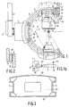
- Fig. 1 shows a vertical column 2 and a sleeve 4 secured thereto.
- the sleeve 4 is rotatable about an axis A and supports a two-armed support 6 (in this case in the form of a C-arc).
- the support 6 is provided on both sides with slots 8 (only one of which is visible in the Figure) in which there are arranged bearing wheels 10, and is movable in the sleeve 4 in the direction of an arrow B.
- an X-ray source 12 At one end of the support 6 there is situated an X-ray source 12 which emits an X-ray beam which is incident on an entrance screen 14 of an X-ray image intensifier tube 16.
- the X-ray image intensifier tube 16 converts an X-ray image of a body arranged betwen the X-ray source 12 and the X-ray detector 16 into a visible image which is detected by means of a video camera 18.
- the centre of gravity of the support 6 is situated in a position 20, the common centre of gravity of the X-ray source 12 and the support 6 being situated in a point 22.
- the X-ray image intensifier tube 16 has a centre of gravity in a position 25, a counterweight 26 having a centre of gravity in a position 27. Movement of the X-ray image intensifier tube 16 parallel to the axis C is guided by wheels 29, transmission means 30 transferring to the counterweight 26 a motion of the X-ray image intensifier tube in the opposite direction.
- a movement of the counterweight 26 is guided by wheels 31.
- the X-ray image intensifier tube 16 is moved in the direction of an arrow D by means of a grip 28 connected to the X-ray image intensifier tube
- the counterweight 26 coupled to the X-ray image intensifier tube is moved in the direction of an arrow E.
- the common centre of gravity of the X-ray image intensifier tube and the counterweight remains in the position 23 and the common centre of gravity of the support 6, the X-ray source 12 and the combination formed by the X-ray image intensifier tube and the counterweight remains in the position 24 which is situated on the second axis of rotation which extends perpendicularly to the plane of drawing.
- the common centre of gravity of the sleeve 4, the arm 6, the X-ray source 12 and the combination formed by the image intensifier tube and the counterweight is situated on the axis A, so that the X-ray examination apparatus is balanced during rotation about the axis A.
- Fig. 1b is a plan view of the sleeve 4 and the support 6.
- the centre of gravity of the sleeve 4 is situated in a position 50 so that the common centre of gravity is situated in a position 52 on the first horizontal axis A.
- Fig. 2 diagrammatically illustrates the coupling of the movement of the X-ray image intensifier tube and the counterweight.
- a drive belt or chain 36 which extends in a closed loop around two pulleys 38 and whereto the X-ray image intensifier tube as well as the counterweight are secured, the movement of the X-ray image intensifier tube is transferred to the counterweight in the opposite direction.
- Fig. 3 is a cross-sectional view of a C-shaped support, taken along a line Q-Q in Fig. 1.
- the wall thickness of an inner side 58 and an outer side 60 of the casting amounts to 5 mm, the thickness of the side walls being 8 mm.
- the profile has an optimum stiffness to weight ratio.
- an opening for the passage of cables for example for powering the X-ray source or for transporting X-ray detector signals.
- the supporting arm is preferably made of cast AlSi10Mg(CU)WA or AlZn10Si8Mg or equivalent, comparatively light materials.
- AlZn10Si8Mg has the advantage of cold hardening, so that it is not necessary to harden the C-shaped supporting arm in, for example an oven.
Landscapes
- Health & Medical Sciences (AREA)
- Life Sciences & Earth Sciences (AREA)
- Medical Informatics (AREA)
- Engineering & Computer Science (AREA)
- Radiology & Medical Imaging (AREA)
- Molecular Biology (AREA)
- Biophysics (AREA)
- Nuclear Medicine, Radiotherapy & Molecular Imaging (AREA)
- Optics & Photonics (AREA)
- Pathology (AREA)
- Physics & Mathematics (AREA)
- Biomedical Technology (AREA)
- Heart & Thoracic Surgery (AREA)
- High Energy & Nuclear Physics (AREA)
- Surgery (AREA)
- Animal Behavior & Ethology (AREA)
- General Health & Medical Sciences (AREA)
- Public Health (AREA)
- Veterinary Medicine (AREA)
- Apparatus For Radiation Diagnosis (AREA)
- Radiography Using Non-Light Waves (AREA)
- Nuclear Medicine (AREA)
Claims (4)
- Röntgenuntersuchungsgerät mit einer Vertikalsäule (2), einer Hülse (4), die mit der Säule verbunden und um eine erste Horizontalachse (A) drehbar ist, und mit einem C-förmigen Träger (6), den die die Hülse trägt und der in der Hülse um eine zweite Achse (F) bewegbar ist, die die erste Achse senkrecht schneidet, wobei der C-förmige Träger eine Röntgenquelle (12) an einem ersten Ende und einen Röntgendetektor (16) an einem zweiten Ende aufnimmt, und der Röntgendetektor längs einem Zentralstrahl (C) eines Röntgenstrahls aus der Röntgenquelle bewegbar ist, dadurch gekennzeichnet, daß eine Verschiebung eines Schwerepunkts (25) des Röntgendetektors (16) längs des Zentralstrahls (C) im wesentlichen durch ein Gegengewicht (26) ausgeglichen wird, das am zweiten Ende des Trägers (6) befestigt ist und dessen Bewegungsrichtung der des Röntgendetektors entgegengesetzt ist, daß ein gemeinsamer Schwerepunkt (24) des Trägers (6), der Röntgenquelle (12), des Röntgendetektors (16) und des Gegengewichts (26) auf der zweiten Achse (F) für einen einstellbaren Abstandsbereich zwischen dem Röntgendetektor und der Röntgenquelle angeordnet ist, und daß ein gemeinsames Schwerezentrum (52) der Hülse (4), des Trägers (6), des Röntgendetektors (16), der Röntgenquelle (1w) und des Gegengewichts (26) sich auf der ersten horizontalen Achse (A) für einen einstellbaren Abstandsbereich zwischen dem Röntgendetektor und der Röntgenquelle befindet.
- Röntgenuntersuchungsgerät nach Anspruch 1, dadurch gekennzeichnet, daß der C-förmige Träger (6) durch ein rohrförmiges Profil gebildet wird, daß mit zwei Laufflächen (11) auf einer Außenseite ausgerüstet ist, und dieses Profil innere Trennwände (62) enthält, wobei das Profil, die Laufflächen und die Trennwände durch ein einziges Gußstück mit einer Wanddicke zwischen etwa 8 und 5 mm hergestellt sind.
- Röntgenuntersuchungsgerät nach Anspruch 1, dadurch gekennzeichnet, daß der Röntgendetektor (16) durch eine Röntgenbildverstärkerröhre gebildet wird.
- Röntgenuntersuchungsgerät nach Anspruch 2, dadurch gekennzeichnet, daß der C-förmige Träger (6) eine der Legierungen G-AlSi10Mg(CU)WA und G-AlZn10Si8Mg enthält.
Applications Claiming Priority (2)
| Application Number | Priority Date | Filing Date | Title |
|---|---|---|---|
| NL8801750 | 1988-07-11 | ||
| NL8801750A NL8801750A (nl) | 1988-07-11 | 1988-07-11 | Roentgenonderzoekapparaat met een uitgebalanceerde statiefarm. |
Publications (2)
| Publication Number | Publication Date |
|---|---|
| EP0350996A1 EP0350996A1 (de) | 1990-01-17 |
| EP0350996B1 true EP0350996B1 (de) | 1993-12-29 |
Family
ID=19852603
Family Applications (1)
| Application Number | Title | Priority Date | Filing Date |
|---|---|---|---|
| EP89201776A Expired - Lifetime EP0350996B1 (de) | 1988-07-11 | 1989-07-05 | Tragarm mit Gewichtsausgleich für ein Röntgenuntersuchungsgerät |
Country Status (5)
| Country | Link |
|---|---|
| US (2) | US4961214A (de) |
| EP (1) | EP0350996B1 (de) |
| JP (1) | JPH0284636A (de) |
| DE (1) | DE68911777T2 (de) |
| NL (1) | NL8801750A (de) |
Cited By (9)
| Publication number | Priority date | Publication date | Assignee | Title |
|---|---|---|---|---|
| US6990368B2 (en) | 2002-04-04 | 2006-01-24 | Surgical Navigation Technologies, Inc. | Method and apparatus for virtual digital subtraction angiography |
| US7130676B2 (en) | 1998-08-20 | 2006-10-31 | Sofamor Danek Holdings, Inc. | Fluoroscopic image guided orthopaedic surgery system with intraoperative registration |
| US7606613B2 (en) | 1999-03-23 | 2009-10-20 | Medtronic Navigation, Inc. | Navigational guidance via computer-assisted fluoroscopic imaging |
| US7630753B2 (en) | 2002-02-28 | 2009-12-08 | Medtronic Navigation, Inc. | Method and apparatus for perspective inversion |
| US7818044B2 (en) | 2003-10-17 | 2010-10-19 | Medtronic Navigation, Inc. | Method and apparatus for surgical navigation |
| US7925328B2 (en) | 2003-08-28 | 2011-04-12 | Medtronic Navigation, Inc. | Method and apparatus for performing stereotactic surgery |
| US8200314B2 (en) | 1992-08-14 | 2012-06-12 | British Telecommunications Public Limited Company | Surgical navigation |
| US8696685B2 (en) | 2002-04-17 | 2014-04-15 | Covidien Lp | Endoscope structures and techniques for navigating to a target in branched structure |
| USRE46422E1 (en) | 1997-11-20 | 2017-06-06 | Medtronic Navigation, Inc. | Image guided awl/tap/screwdriver |
Families Citing this family (92)
| Publication number | Priority date | Publication date | Assignee | Title |
|---|---|---|---|---|
| FR2652928B1 (fr) | 1989-10-05 | 1994-07-29 | Diadix Sa | Systeme interactif d'intervention locale a l'interieur d'une zone d'une structure non homogene. |
| NL8902885A (nl) * | 1989-11-22 | 1991-06-17 | Philips Nv | Roentgenonderzoekapparaat. |
| JPH03176033A (ja) * | 1989-12-06 | 1991-07-31 | Toshiba Corp | X線撮影装置 |
| US5052036A (en) * | 1990-04-02 | 1991-09-24 | Grady John K | X-ray stand with laterally inclined rotation axis |
| DE69119904T2 (de) * | 1991-10-30 | 1996-11-28 | Philips Electronics Nv | Röntgenuntersuchungsgerät |
| US5311785A (en) * | 1992-03-11 | 1994-05-17 | Nucleonics Development Company | Probe holder for a rotary scanner |
| FR2698721B1 (fr) * | 1992-11-27 | 1995-01-27 | Gen Electric Cgr | Système de refroidissement d'une anode pour tube à rayons X dans un bloc radiogène sans échangeur de chaleur. |
| DE4319598C2 (de) * | 1993-06-14 | 1996-02-22 | Siemens Ag | Medizinisches Gerät mit einem C-Bogen und einer Kabelführung |
| BE1007873A3 (nl) * | 1993-12-15 | 1995-11-07 | Philips Electronics Nv | Röntgenonderzoekapparaat met een uitgebalanceerde röntgendetector. |
| US5426683A (en) * | 1994-03-14 | 1995-06-20 | Oec Medical Systems, Inc. | One piece C-arm for X-ray diagnostic equipment |
| JP3246192B2 (ja) * | 1994-06-30 | 2002-01-15 | 三菱電機株式会社 | 放射線照射装置 |
| SE9403497L (sv) * | 1994-10-13 | 1996-04-14 | Swemac Orthopaedics Internatio | Anordning för att visa röntgenbilder |
| JPH09509354A (ja) * | 1994-12-12 | 1997-09-22 | フィリップス エレクトロニクス エヌ ベー | 複合c字型アークプロファイルからなる医学診断及び/又は治療装置 |
| US5592939A (en) | 1995-06-14 | 1997-01-14 | Martinelli; Michael A. | Method and system for navigating a catheter probe |
| US5627873B1 (en) * | 1995-08-04 | 2000-03-14 | Oec Medical Systems | Mini c-arm assembly for mobile x-ray imaging system |
| US5772594A (en) * | 1995-10-17 | 1998-06-30 | Barrick; Earl F. | Fluoroscopic image guided orthopaedic surgery system with intraoperative registration |
| US6226548B1 (en) | 1997-09-24 | 2001-05-01 | Surgical Navigation Technologies, Inc. | Percutaneous registration apparatus and method for use in computer-assisted surgical navigation |
| DE19746079C2 (de) | 1997-10-17 | 1999-10-28 | Siemens Ag | Medizinische Einrichtung mit einer Tragevorrichtung für mindestens eine Komponente |
| US6348058B1 (en) | 1997-12-12 | 2002-02-19 | Surgical Navigation Technologies, Inc. | Image guided spinal surgery guide, system, and method for use thereof |
| US6147352A (en) * | 1998-02-23 | 2000-11-14 | Digirad Corporation | Low profile open ring single photon emission computed tomographic imager |
| US6142667A (en) * | 1998-09-21 | 2000-11-07 | Oec Medical Systems, Inc. | Gas-spring assisted, counter-balanced L-arm assembly for fluoroscopic imaging |
| US6491699B1 (en) | 1999-04-20 | 2002-12-10 | Surgical Navigation Technologies, Inc. | Instrument guidance method and system for image guided surgery |
| US6381485B1 (en) | 1999-10-28 | 2002-04-30 | Surgical Navigation Technologies, Inc. | Registration of human anatomy integrated for electromagnetic localization |
| US6499488B1 (en) | 1999-10-28 | 2002-12-31 | Winchester Development Associates | Surgical sensor |
| US8644907B2 (en) | 1999-10-28 | 2014-02-04 | Medtronic Navigaton, Inc. | Method and apparatus for surgical navigation |
| US6379302B1 (en) | 1999-10-28 | 2002-04-30 | Surgical Navigation Technologies Inc. | Navigation information overlay onto ultrasound imagery |
| US6474341B1 (en) | 1999-10-28 | 2002-11-05 | Surgical Navigation Technologies, Inc. | Surgical communication and power system |
| US8239001B2 (en) | 2003-10-17 | 2012-08-07 | Medtronic Navigation, Inc. | Method and apparatus for surgical navigation |
| US6493573B1 (en) | 1999-10-28 | 2002-12-10 | Winchester Development Associates | Method and system for navigating a catheter probe in the presence of field-influencing objects |
| US11331150B2 (en) | 1999-10-28 | 2022-05-17 | Medtronic Navigation, Inc. | Method and apparatus for surgical navigation |
| US6725080B2 (en) | 2000-03-01 | 2004-04-20 | Surgical Navigation Technologies, Inc. | Multiple cannula image guided tool for image guided procedures |
| US6535756B1 (en) | 2000-04-07 | 2003-03-18 | Surgical Navigation Technologies, Inc. | Trajectory storage apparatus and method for surgical navigation system |
| US7085400B1 (en) | 2000-06-14 | 2006-08-01 | Surgical Navigation Technologies, Inc. | System and method for image based sensor calibration |
| US6636757B1 (en) | 2001-06-04 | 2003-10-21 | Surgical Navigation Technologies, Inc. | Method and apparatus for electromagnetic navigation of a surgical probe near a metal object |
| US6789941B1 (en) * | 2002-05-24 | 2004-09-14 | Grady John K | Dual C-arm angiographic device for flat panel receptor |
| US6892090B2 (en) | 2002-08-19 | 2005-05-10 | Surgical Navigation Technologies, Inc. | Method and apparatus for virtual endoscopy |
| US7599730B2 (en) | 2002-11-19 | 2009-10-06 | Medtronic Navigation, Inc. | Navigation system for cardiac therapies |
| US7697972B2 (en) | 2002-11-19 | 2010-04-13 | Medtronic Navigation, Inc. | Navigation system for cardiac therapies |
| US7542791B2 (en) | 2003-01-30 | 2009-06-02 | Medtronic Navigation, Inc. | Method and apparatus for preplanning a surgical procedure |
| US7660623B2 (en) | 2003-01-30 | 2010-02-09 | Medtronic Navigation, Inc. | Six degree of freedom alignment display for medical procedures |
| US7570791B2 (en) | 2003-04-25 | 2009-08-04 | Medtronic Navigation, Inc. | Method and apparatus for performing 2D to 3D registration |
| EP1667749B1 (de) | 2003-09-15 | 2009-08-05 | Super Dimension Ltd. | System aus zubehör zur verwendung mit bronchoskopen |
| EP2316328B1 (de) | 2003-09-15 | 2012-05-09 | Super Dimension Ltd. | Umhüllungsvorrichtung zur Fixierung von Bronchoskopen |
| US7835778B2 (en) | 2003-10-16 | 2010-11-16 | Medtronic Navigation, Inc. | Method and apparatus for surgical navigation of a multiple piece construct for implantation |
| US7840253B2 (en) | 2003-10-17 | 2010-11-23 | Medtronic Navigation, Inc. | Method and apparatus for surgical navigation |
| US8764725B2 (en) | 2004-02-09 | 2014-07-01 | Covidien Lp | Directional anchoring mechanism, method and applications thereof |
| DE102004011460B4 (de) * | 2004-03-09 | 2011-07-14 | Siemens AG, 80333 | C-Bogen-Gerät mit Gewichtsausgleich |
| US7567834B2 (en) | 2004-05-03 | 2009-07-28 | Medtronic Navigation, Inc. | Method and apparatus for implantation between two vertebral bodies |
| US7636595B2 (en) | 2004-10-28 | 2009-12-22 | Medtronic Navigation, Inc. | Method and apparatus for calibrating non-linear instruments |
| US7835784B2 (en) | 2005-09-21 | 2010-11-16 | Medtronic Navigation, Inc. | Method and apparatus for positioning a reference frame |
| US9168102B2 (en) | 2006-01-18 | 2015-10-27 | Medtronic Navigation, Inc. | Method and apparatus for providing a container to a sterile environment |
| US8112292B2 (en) | 2006-04-21 | 2012-02-07 | Medtronic Navigation, Inc. | Method and apparatus for optimizing a therapy |
| US8660635B2 (en) | 2006-09-29 | 2014-02-25 | Medtronic, Inc. | Method and apparatus for optimizing a computer assisted surgical procedure |
| US8995619B2 (en) | 2010-03-14 | 2015-03-31 | Rapiscan Systems, Inc. | Personnel screening system |
| US8638904B2 (en) | 2010-03-14 | 2014-01-28 | Rapiscan Systems, Inc. | Personnel screening system |
| US8576982B2 (en) | 2008-02-01 | 2013-11-05 | Rapiscan Systems, Inc. | Personnel screening system |
| US8905920B2 (en) | 2007-09-27 | 2014-12-09 | Covidien Lp | Bronchoscope adapter and method |
| US9575140B2 (en) | 2008-04-03 | 2017-02-21 | Covidien Lp | Magnetic interference detection system and method |
| EP2297673B1 (de) | 2008-06-03 | 2020-04-22 | Covidien LP | Registrationsverfahren auf merkmalbasis |
| US8218847B2 (en) | 2008-06-06 | 2012-07-10 | Superdimension, Ltd. | Hybrid registration method |
| US8932207B2 (en) | 2008-07-10 | 2015-01-13 | Covidien Lp | Integrated multi-functional endoscopic tool |
| US8794832B2 (en) * | 2008-09-03 | 2014-08-05 | Kabushiki Kaisha Toshiba | X-ray diagnostic imaging apparatus and X-ray apparatus |
| US8165658B2 (en) | 2008-09-26 | 2012-04-24 | Medtronic, Inc. | Method and apparatus for positioning a guide relative to a base |
| US8175681B2 (en) | 2008-12-16 | 2012-05-08 | Medtronic Navigation Inc. | Combination of electromagnetic and electropotential localization |
| US8611984B2 (en) | 2009-04-08 | 2013-12-17 | Covidien Lp | Locatable catheter |
| US8494614B2 (en) | 2009-08-31 | 2013-07-23 | Regents Of The University Of Minnesota | Combination localization system |
| US8494613B2 (en) | 2009-08-31 | 2013-07-23 | Medtronic, Inc. | Combination localization system |
| CN102893341A (zh) | 2010-03-14 | 2013-01-23 | 拉皮斯坎系统股份有限公司 | 波束形成装置 |
| JP2013522626A (ja) * | 2010-03-14 | 2013-06-13 | ラピスカン システムズ、インコーポレイテッド | 人員検査システム |
| US10582834B2 (en) | 2010-06-15 | 2020-03-10 | Covidien Lp | Locatable expandable working channel and method |
| JP5931371B2 (ja) * | 2010-08-18 | 2016-06-08 | 株式会社東芝 | X線診断装置 |
| US11280898B2 (en) | 2014-03-07 | 2022-03-22 | Rapiscan Systems, Inc. | Radar-based baggage and parcel inspection systems |
| KR20160130482A (ko) | 2014-03-07 | 2016-11-11 | 라피스캔 시스템스, 인코포레이티드 | 초광대역 검출기 |
| US10952593B2 (en) | 2014-06-10 | 2021-03-23 | Covidien Lp | Bronchoscope adapter |
| JP2017537399A (ja) | 2014-11-25 | 2017-12-14 | ラピスカン システムズ、インコーポレイテッド | インテリジェントセキュリティ管理システム |
| US10426555B2 (en) | 2015-06-03 | 2019-10-01 | Covidien Lp | Medical instrument with sensor for use in a system and method for electromagnetic navigation |
| US9962134B2 (en) | 2015-10-28 | 2018-05-08 | Medtronic Navigation, Inc. | Apparatus and method for maintaining image quality while minimizing X-ray dosage of a patient |
| CN105263250A (zh) * | 2015-11-11 | 2016-01-20 | 丹东奥龙射线仪器集团有限公司 | X射线机的提手及支座装置 |
| US10478254B2 (en) | 2016-05-16 | 2019-11-19 | Covidien Lp | System and method to access lung tissue |
| EP3520120A4 (de) | 2016-09-30 | 2020-07-08 | American Science & Engineering, Inc. | Röntgenstrahlenquelle zur zweidimensionalen abtaststrahlbildgebung |
| US10792106B2 (en) | 2016-10-28 | 2020-10-06 | Covidien Lp | System for calibrating an electromagnetic navigation system |
| US10638952B2 (en) | 2016-10-28 | 2020-05-05 | Covidien Lp | Methods, systems, and computer-readable media for calibrating an electromagnetic navigation system |
| US10722311B2 (en) | 2016-10-28 | 2020-07-28 | Covidien Lp | System and method for identifying a location and/or an orientation of an electromagnetic sensor based on a map |
| US10517505B2 (en) | 2016-10-28 | 2019-12-31 | Covidien Lp | Systems, methods, and computer-readable media for optimizing an electromagnetic navigation system |
| US10446931B2 (en) | 2016-10-28 | 2019-10-15 | Covidien Lp | Electromagnetic navigation antenna assembly and electromagnetic navigation system including the same |
| US10418705B2 (en) | 2016-10-28 | 2019-09-17 | Covidien Lp | Electromagnetic navigation antenna assembly and electromagnetic navigation system including the same |
| US10615500B2 (en) | 2016-10-28 | 2020-04-07 | Covidien Lp | System and method for designing electromagnetic navigation antenna assemblies |
| US10751126B2 (en) | 2016-10-28 | 2020-08-25 | Covidien Lp | System and method for generating a map for electromagnetic navigation |
| US11219489B2 (en) | 2017-10-31 | 2022-01-11 | Covidien Lp | Devices and systems for providing sensors in parallel with medical tools |
| US12089902B2 (en) | 2019-07-30 | 2024-09-17 | Coviden Lp | Cone beam and 3D fluoroscope lung navigation |
| US11457883B1 (en) | 2021-04-09 | 2022-10-04 | Pulmera, Inc. | Medical imaging systems and associated devices and methods |
| CN113984804A (zh) * | 2021-11-22 | 2022-01-28 | 赛诺威盛科技(北京)股份有限公司 | 动态平衡装置及x光机 |
Citations (1)
| Publication number | Priority date | Publication date | Assignee | Title |
|---|---|---|---|---|
| US3892967A (en) * | 1973-12-10 | 1975-07-01 | Measurex Corp | Apparatus for radiological examination of a subject through a solid angle |
Family Cites Families (5)
| Publication number | Priority date | Publication date | Assignee | Title |
|---|---|---|---|---|
| US3281598A (en) * | 1965-11-19 | 1966-10-25 | Picker X Ray Corp Waite Mfg | Overhead support for a vertically and rotatably movable x-ray tube support arm and cooperating tiltable x-ray table |
| FR1526087A (fr) * | 1967-03-30 | 1968-05-24 | Man Sa Ets De | Perfectionnements aux systèmes d'entraînement et de guidage des câbles d'alimentation en énergie électrique notamment des appareils de radiologie comportant des organes mobiles |
| US4363128A (en) * | 1980-09-29 | 1982-12-07 | John K. Grady | X-Ray drive apparatus |
| JPS57178932A (en) * | 1981-04-28 | 1982-11-04 | Tominaga Oil Pump Mfg Co Ltd | Oil supply nozzle attachment |
| NL8102286A (nl) * | 1981-05-11 | 1981-07-01 | Philips Nv | Medisch apparaat. |
-
1988
- 1988-07-11 NL NL8801750A patent/NL8801750A/nl not_active Application Discontinuation
-
1989
- 1989-06-22 US US07/370,213 patent/US4961214A/en not_active Ceased
- 1989-07-05 EP EP89201776A patent/EP0350996B1/de not_active Expired - Lifetime
- 1989-07-05 DE DE68911777T patent/DE68911777T2/de not_active Expired - Fee Related
- 1989-07-10 JP JP1175752A patent/JPH0284636A/ja active Pending
-
1992
- 1992-10-02 US US07/955,958 patent/USRE34943E/en not_active Expired - Lifetime
Patent Citations (1)
| Publication number | Priority date | Publication date | Assignee | Title |
|---|---|---|---|---|
| US3892967A (en) * | 1973-12-10 | 1975-07-01 | Measurex Corp | Apparatus for radiological examination of a subject through a solid angle |
Cited By (10)
| Publication number | Priority date | Publication date | Assignee | Title |
|---|---|---|---|---|
| US8200314B2 (en) | 1992-08-14 | 2012-06-12 | British Telecommunications Public Limited Company | Surgical navigation |
| USRE46422E1 (en) | 1997-11-20 | 2017-06-06 | Medtronic Navigation, Inc. | Image guided awl/tap/screwdriver |
| US7130676B2 (en) | 1998-08-20 | 2006-10-31 | Sofamor Danek Holdings, Inc. | Fluoroscopic image guided orthopaedic surgery system with intraoperative registration |
| US7606613B2 (en) | 1999-03-23 | 2009-10-20 | Medtronic Navigation, Inc. | Navigational guidance via computer-assisted fluoroscopic imaging |
| US7630753B2 (en) | 2002-02-28 | 2009-12-08 | Medtronic Navigation, Inc. | Method and apparatus for perspective inversion |
| US6990368B2 (en) | 2002-04-04 | 2006-01-24 | Surgical Navigation Technologies, Inc. | Method and apparatus for virtual digital subtraction angiography |
| US8696685B2 (en) | 2002-04-17 | 2014-04-15 | Covidien Lp | Endoscope structures and techniques for navigating to a target in branched structure |
| US7925328B2 (en) | 2003-08-28 | 2011-04-12 | Medtronic Navigation, Inc. | Method and apparatus for performing stereotactic surgery |
| US7818044B2 (en) | 2003-10-17 | 2010-10-19 | Medtronic Navigation, Inc. | Method and apparatus for surgical navigation |
| US7971341B2 (en) | 2003-10-17 | 2011-07-05 | Medtronic Navigation, Inc. | Method of forming an electromagnetic sensing coil in a medical instrument for a surgical navigation system |
Also Published As
| Publication number | Publication date |
|---|---|
| DE68911777D1 (de) | 1994-02-10 |
| JPH0284636A (ja) | 1990-03-26 |
| DE68911777T2 (de) | 1994-07-07 |
| USRE34943E (en) | 1995-05-16 |
| NL8801750A (nl) | 1990-02-01 |
| EP0350996A1 (de) | 1990-01-17 |
| US4961214A (en) | 1990-10-02 |
Similar Documents
| Publication | Publication Date | Title |
|---|---|---|
| US4961214A (en) | X-ray examination apparatus comprising a balanced supporting arm | |
| US4412346A (en) | X-Ray photography apparatus | |
| US3281598A (en) | Overhead support for a vertically and rotatably movable x-ray tube support arm and cooperating tiltable x-ray table | |
| US4501011A (en) | Angulating lateral fluoroscopic suspension | |
| US6184530B1 (en) | Adjustable dual-detector image data acquisition system | |
| US7949094B2 (en) | Rail system and X-ray imaging apparatus using the same | |
| US5097132A (en) | Nuclear medicine camera system with improved gantry and patient table | |
| US5073917A (en) | X-ray examination apparatus | |
| EP0511379B1 (de) | Kameragehäuse für nuklearmedizin mit senkrecht gelagerten kollimatoren | |
| US2822477A (en) | X-ray apparatus | |
| EP4368979A1 (de) | Strahlenabtastvorrichtung | |
| JPH02277443A (ja) | X線撮影装置 | |
| EP0539626B1 (de) | Röntgenuntersuchungsgerät | |
| US5093575A (en) | Dual rotatable head gamma camera | |
| US4761805A (en) | X-ray receptor interchange mechanism | |
| US3714423A (en) | Specimen stages for electron microscopes | |
| Goto et al. | Standard transport channels of X-ray beamlines at SPring-8 | |
| US4149078A (en) | Counterweight compensation for an X-ray examination apparatus | |
| US4190774A (en) | Radiographic table system | |
| JPH07213514A (ja) | バランス型x線検出器からなるx線検査装置 | |
| GB1597647A (en) | Gantry for computed tomography | |
| US6386759B2 (en) | X-ray diagnostic device having a supporting apparatus | |
| EP4369060A1 (de) | Strahlenabtastvorrichtung | |
| US2311581A (en) | X-kay apparatus | |
| US20240407740A1 (en) | Integrated computed tomography rotating base with an integrated drive system |
Legal Events
| Date | Code | Title | Description |
|---|---|---|---|
| PUAI | Public reference made under article 153(3) epc to a published international application that has entered the european phase |
Free format text: ORIGINAL CODE: 0009012 |
|
| AK | Designated contracting states |
Kind code of ref document: A1 Designated state(s): DE FR GB IT NL |
|
| 17P | Request for examination filed |
Effective date: 19900713 |
|
| 17Q | First examination report despatched |
Effective date: 19921012 |
|
| GRAA | (expected) grant |
Free format text: ORIGINAL CODE: 0009210 |
|
| AK | Designated contracting states |
Kind code of ref document: B1 Designated state(s): DE FR GB IT NL |
|
| PG25 | Lapsed in a contracting state [announced via postgrant information from national office to epo] |
Ref country code: NL Effective date: 19931229 |
|
| REF | Corresponds to: |
Ref document number: 68911777 Country of ref document: DE Date of ref document: 19940210 |
|
| ITF | It: translation for a ep patent filed | ||
| ET | Fr: translation filed | ||
| NLV1 | Nl: lapsed or annulled due to failure to fulfill the requirements of art. 29p and 29m of the patents act | ||
| PLBE | No opposition filed within time limit |
Free format text: ORIGINAL CODE: 0009261 |
|
| STAA | Information on the status of an ep patent application or granted ep patent |
Free format text: STATUS: NO OPPOSITION FILED WITHIN TIME LIMIT |
|
| 26N | No opposition filed | ||
| ITPR | It: changes in ownership of a european patent |
Owner name: CAMBIO RAGIONE SOCIALE;PHILIPS ELECTRONICS N.V. |
|
| REG | Reference to a national code |
Ref country code: FR Ref legal event code: CD |
|
| REG | Reference to a national code |
Ref country code: FR Ref legal event code: CD |
|
| REG | Reference to a national code |
Ref country code: GB Ref legal event code: 746 Effective date: 20010820 |
|
| REG | Reference to a national code |
Ref country code: FR Ref legal event code: D6 |
|
| REG | Reference to a national code |
Ref country code: GB Ref legal event code: IF02 |
|
| PG25 | Lapsed in a contracting state [announced via postgrant information from national office to epo] |
Ref country code: IT Free format text: LAPSE BECAUSE OF NON-PAYMENT OF DUE FEES;WARNING: LAPSES OF ITALIAN PATENTS WITH EFFECTIVE DATE BEFORE 2007 MAY HAVE OCCURRED AT ANY TIME BEFORE 2007. THE CORRECT EFFECTIVE DATE MAY BE DIFFERENT FROM THE ONE RECORDED. Effective date: 20050705 |
|
| PGFP | Annual fee paid to national office [announced via postgrant information from national office to epo] |
Ref country code: DE Payment date: 20070919 Year of fee payment: 19 |
|
| PGFP | Annual fee paid to national office [announced via postgrant information from national office to epo] |
Ref country code: GB Payment date: 20070905 Year of fee payment: 19 |
|
| PGFP | Annual fee paid to national office [announced via postgrant information from national office to epo] |
Ref country code: FR Payment date: 20070725 Year of fee payment: 19 |
|
| GBPC | Gb: european patent ceased through non-payment of renewal fee |
Effective date: 20080705 |
|
| PG25 | Lapsed in a contracting state [announced via postgrant information from national office to epo] |
Ref country code: DE Free format text: LAPSE BECAUSE OF NON-PAYMENT OF DUE FEES Effective date: 20090203 |
|
| REG | Reference to a national code |
Ref country code: FR Ref legal event code: ST Effective date: 20090331 |
|
| PG25 | Lapsed in a contracting state [announced via postgrant information from national office to epo] |
Ref country code: GB Free format text: LAPSE BECAUSE OF NON-PAYMENT OF DUE FEES Effective date: 20080705 |
|
| PG25 | Lapsed in a contracting state [announced via postgrant information from national office to epo] |
Ref country code: FR Free format text: LAPSE BECAUSE OF NON-PAYMENT OF DUE FEES Effective date: 20080731 |