EP0351030B2 - Pflanzentopf sowie Verfahren und Form zu seiner Herstellung - Google Patents
Pflanzentopf sowie Verfahren und Form zu seiner Herstellung Download PDFInfo
- Publication number
- EP0351030B2 EP0351030B2 EP19890201902 EP89201902A EP0351030B2 EP 0351030 B2 EP0351030 B2 EP 0351030B2 EP 19890201902 EP19890201902 EP 19890201902 EP 89201902 A EP89201902 A EP 89201902A EP 0351030 B2 EP0351030 B2 EP 0351030B2
- Authority
- EP
- European Patent Office
- Prior art keywords
- tray
- mould
- pot
- sliding pieces
- angle
- Prior art date
- Legal status (The legal status is an assumption and is not a legal conclusion. Google has not performed a legal analysis and makes no representation as to the accuracy of the status listed.)
- Expired - Lifetime
Links
Images

Classifications
-
- B—PERFORMING OPERATIONS; TRANSPORTING
- B29—WORKING OF PLASTICS; WORKING OF SUBSTANCES IN A PLASTIC STATE IN GENERAL
- B29C—SHAPING OR JOINING OF PLASTICS; SHAPING OF MATERIAL IN A PLASTIC STATE, NOT OTHERWISE PROVIDED FOR; AFTER-TREATMENT OF THE SHAPED PRODUCTS, e.g. REPAIRING
- B29C45/00—Injection moulding, i.e. forcing the required volume of moulding material through a nozzle into a closed mould; Apparatus therefor
- B29C45/17—Component parts, details or accessories; Auxiliary operations
- B29C45/26—Moulds
- B29C45/33—Moulds having transversely, e.g. radially, movable mould parts
-
- A—HUMAN NECESSITIES
- A01—AGRICULTURE; FORESTRY; ANIMAL HUSBANDRY; HUNTING; TRAPPING; FISHING
- A01G—HORTICULTURE; CULTIVATION OF VEGETABLES, FLOWERS, RICE, FRUIT, VINES, HOPS OR SEAWEED; FORESTRY; WATERING
- A01G9/00—Cultivation in receptacles, forcing-frames or greenhouses; Edging for beds, lawn or the like
- A01G9/02—Receptacles, e.g. flower-pots or boxes; Glasses for cultivating flowers
- A01G9/021—Pots formed in one piece; Materials used therefor
-
- B—PERFORMING OPERATIONS; TRANSPORTING
- B29—WORKING OF PLASTICS; WORKING OF SUBSTANCES IN A PLASTIC STATE IN GENERAL
- B29C—SHAPING OR JOINING OF PLASTICS; SHAPING OF MATERIAL IN A PLASTIC STATE, NOT OTHERWISE PROVIDED FOR; AFTER-TREATMENT OF THE SHAPED PRODUCTS, e.g. REPAIRING
- B29C45/00—Injection moulding, i.e. forcing the required volume of moulding material through a nozzle into a closed mould; Apparatus therefor
- B29C45/17—Component parts, details or accessories; Auxiliary operations
- B29C45/40—Removing or ejecting moulded articles
- B29C45/44—Removing or ejecting moulded articles for undercut articles
- B29C45/4435—Removing or ejecting moulded articles for undercut articles using inclined, tiltable or flexible undercut forming elements driven by the ejector means
-
- B—PERFORMING OPERATIONS; TRANSPORTING
- B29—WORKING OF PLASTICS; WORKING OF SUBSTANCES IN A PLASTIC STATE IN GENERAL
- B29L—INDEXING SCHEME ASSOCIATED WITH SUBCLASS B29C, RELATING TO PARTICULAR ARTICLES
- B29L2031/00—Other particular articles
- B29L2031/712—Containers; Packaging elements or accessories, Packages
- B29L2031/7136—Vases, pots, e.g. for flowers
Definitions
- This invention relates to a plant container as defined in the preamble of claim 1. Such a container is disclosed in CH-372.495.
- a first specific object of the invention is to design a plant container in such a way, that the container can be nested over a large distance in a pot of an identical plant container, so that nested containers occupy little space during storage and transport.
- a second specific object of the invention is to achieve the above object while simultaneously assuring that the height of the rim of the tray is such that the tray can take up a sufficiently large volume of liquid.
- a third specific object of the invention is to provide a plant container which can be easily manufactured.
- the invention seeks to attain the above objectives simultaneously.
- the tray can be nested over a large distance in a pot of an identical flower pot with tray, while the tray can take up a sufficiently large volume of liquid due to the height of its rim.
- the attainable small dimensions of the tray in horizontal direction are likewise advantageous, because when a moulded product is removed from a mould, the tray can be passed through an annular mould portion for forming an upper portion of the wall of the pot.
- the use of divided, complicated mould portions, which cause disfiguring division seams, for moulding the upper portion of the wall of the pot, which is exposed to view in use, can thus be avoided.
- the extension of the wall portion at the lower end of the pot substantially parallel to the rim region of the tray enables mould portions for providing spacing between the rim region of the tray and the wall portion of the pot opposite and substantially parallel thereto to be retracted in a direction parallel to the rim region of the tray.
- the wall portion of the pot extending substantially parallel to the rim region of the tray, extends obliquely downwardly and inwardly relatively to the prolongation of a superimposed part of the wall, with the dimensions of the tray in horizontal directions always being smaller than the largest dimensions in the same direction of the opposite wall portion, a very compact nesting of stacked plant containers can be obtained with a relatively large effective holding capacity of the pot
- a plant container can be nested within the next container with the rim of its tray down to the level of the upper edge of the wall portion of the pot of such next plant container opposite the rim of the tray thereof.
- the plant container according to the present invention can be designed as a said of revolution, but alternatively may be of triangular, polygonal or oval shape in top view.
- the present invention relates to a method of manufacturing a plant container as defined above, using a mould.
- the method according to the present invention provides that, during the removal of the moulded material from the mould, sliding pieces of the mould which, during the moulding process, define a space between the tray and the pot, are displaced with a component in a direction outward from a heartline of the formed pot with tray, at an angle to the opening direction of the mould smaller than the angle at which the generatrices of the top of the rim region of the tray extend with respect of this opening direction.
- This method offers the advantage that the sliding pieces, which are necessary by reason of the different directions of release of the pot and the space between the pot and the tray, can be driven by opening and closing the mould.
- Separate, in particular hydraulic, drive systems are hence superfluous, so that machine cost is limited and the cycle time remains limited to at most half the cost that would be necessary when such separate drive systems are used.
- the advantage is obtained that the sliding pieces, through the use of the resilience of the material from which the product is made, can be pulled out of the space between the tray and the pot even when this space is not fully “releasing”. This is made possible because the difference between the direction of release of that space and the direction of displacement of the sliding pieces results in a displacement of the formed end product in opening direction. Due to this displacement, the tray is released from the mould cavity wherein this has been moulded, affording it an opportunity to deflect, if necessary, in the direction of said cavity when the sliding pieces are retracted.
- the sliding pieces are driven in a very simple manner by springs which are expanded as the mould is being opened.
- the sliding pieces are pressed downwards in inward direction by a superjacent central portion of the mould and at the same time the springs are stressed again.
- the sliding pieces are conducted by, and driven through, pins and, in addition, supported by walls of a part of the mould likewise defining the shape of the underside of the tray, and which walls are parallel to the sliding pieces.
- the pins exert the relatively small forces occurring during unmoulding and further prevent the sliding pieces from getting beyond the desired trajectory.
- the additional support by the walls parallel to the pins ensures the absorption of the substantial forces occurring in the moulding process proper.
- the sliding pieces are displaced relatively to a central portion of the mould bounding the top of these sliding pieces, along boundary surfaces including an angle with the opening direction of the mould.
- the inclination achieves that this central portion, defining the shape of the top portion of the wall of the pot, can drive the displacements of the sliding pieces, thereby remaining centered without additional means, while at the same time the sliding pieces are kept pressed against outer guiding surfaces.
- the central portion of the mould when being opened, extends outwards over a distance smaller than the distance over which the sliding pieces are then displaced in direction of opening of the mould.
- the mould need be opened less far for releasing a moulded flower pot with tray, than would be the case when the central portion should be displaced over an equal distance in the opening direction of the mould as are the sliding pieces. This again leads to an additional shortening of the cycle time and hence of the machine cost per product.
- the present invention relates to a mould for application of the above described method.
- the mould according to the present invention is provided with sliding pieces whose displacement guide includes an angle with the opening direction of the mould smaller than the angle at which the generatrices determining the top of the rim region of the tray extend relative to the opening direction, a central portion linking up with said sliding pieces at the open end of the mould, said central portion adjoining said sliding pieces along boundary surfaces which enclose an angle with the opening direction of the mould that is larger than, or equal to, the angle relative to the opening direction at which said generatrices extend.
- each displacement guide of the sliding pieces encloses a smaller angle with the opening direction of the mould than does the direction at which the generatrices of the cavity parts for forming the top rim region of the tray extend
- the sliding pieces can be driven in a simple manner by the movements of the mould during the opening and closing thereof.
- the simultaneous displacement in outward direction and in the opening direction of the mould makes it possible, using the resilience of the material, to release the sliding pieces from the space between tray and pot defined by these pieces.
- the additional displacement component in the opening direction of the mould be absent, the portion of the tray bounding said space would be prevented by the subjacent mould portion from being resiliently deflected and the respective portion of the sliding piece could not be pulled out of this space.
- the feature that the central portion links up along boundary surfaces with these sliding pieces enclosing an angle with the direction of opening of the mould provides the advantage that the sliding pieces are pressed against the walls of a mould portion abutting therearound and that for releasing a formed product out of the mould, the central portion need be displaced over a smaller distance in the direction of openings of the mould than the distance over which the sliding pieces are displaced in that direction.
- the boundary surfaces along which the sliding pieces link up with the central portion form portions of elliptical cylinder surfaces having separate axes. This enables abutment of these surfaces on a frusto-conical lower portion of the pot, as is preferably employed in an embodiment of the present invention formed as a solid of revolution.
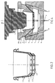
- a plant container according to the present invention consists essentially of the same piece of material, i.e. a pot 12 formed integrally with a tray 16.
- the tray 16 is provided with an rim region 13 which, according to the embodiment shown, forms a cone frustum which extends substantially parallel as viewed in cross section to a wall portion 15 extending near the bottom of pot 12 in upward and outward direction.
- the space between said wall portion 15 and the rim region of the tray is releasable, if necessary using the resilience of the material from which these are made.
- openings which are formed together with the plant container, and, as is kwown per se, serve for venting potting soil or other substrate in the pot and for passing water from pot 12 to tray 16 and vice versa.
- Fig. 2 shows how plant containers according to the embodiment shown in Fig. 1 can be nested in stacked position.
- Such compact stacking is made possible because, as viewed in cross-section, rim region 13 of tray 16 extends substantialy parallel to wall portion 15, while tray 16 has a smaller diameter than the inside of pot 12 at the upper end of this outwardly extending wall portion 15 at the bottom of pot 12.
- a mould for manufacturing the embodiment of the plant container according to Fig. 1 is shown in the closed state in Fig. 3.
- the mould comprises a plurality of parts 1, 3 and 18 movable relatively to a fixed bottom portion.
- Reference numeral 1 indicates a core member of the mould and numeral 2 illustrates a cavity forming the exterior of the flower pot and the tray.
- sliding pieces 3 For forming the space between rim region 13 of tray 16 and wall portion 15 of pot 12, there are provided sliding pieces 3 having pins 4 for their guidance and for transmitting forces for their displacement.
- the displacement in an opening direction indicated with an arrow 9, with simultaneous displacement in outward direction, can be effected by means of springs which are unstressed when the mould is opened.
- the exercise of force of these springs is shown diagrammatically with arrows F.
- Fig. 4 shows the mould according to Fig. 3 in a slightly opened position.
- the sliding pieces are provided with inwardly extending end faces 6, while the space for forming tray 16 has an outside end rim 7.
- the mould is opened so far that the end faces of sliding pieces 3 are located further outwards than the end rim 7.
- the mould is opened sufficiently far to enable a product formed therein to be removed from mould cavity 2, whereby the outside rim of tray 16, defined by the end rim 7 of the cavity forming tray 16, passes along the end faces 6.
- the complete removal of the product requires of course core portion 1 to be displaced further in the opening direction than the position shown in Fig. 4.
- Fig. 4 also shows that, owing to the angle which the guide surfaces 19 make with the opening direction, the central portion 18, when the mould is opened, is displaced less far in the opening direction than are sliding pieces 3, so that the removal of a ready flower pot with tray requires core portion 1 to be displaced less far in the opening direction than would be the case when central portion 18 were displaced equally far in that direction as sliding pieces 3.
- Central portion 18 is always kept centered by the inclined surfaces 19.
- the surfaces 19 are formed as segments of bodies having such an axis and elliptical cross section as to link up with the frusto-conical wall portion 15 of pot 12.
Landscapes
- Engineering & Computer Science (AREA)
- Manufacturing & Machinery (AREA)
- Mechanical Engineering (AREA)
- Life Sciences & Earth Sciences (AREA)
- Environmental Sciences (AREA)
- Cultivation Receptacles Or Flower-Pots, Or Pots For Seedlings (AREA)
- Moulds For Moulding Plastics Or The Like (AREA)
Claims (7)
- Ein Pflanzbehältnis aufweisend einen Topf mit einem oberen offenen Ende und einem Bodenende, welches mit einer Schale verbunden ist, wobei der Topf und die Schale gemeinsam, im wesentlichen einstückig ausgebildet sind, wobei die Schale einen Randbereich aufweist, welcher sich in einer Richtung nach oben, schräg-laufend und auswärts gerichtet erstreckt, dadurch gekennzeichnet, daß das Pflanzbehältnis ein Formprodukt ist, bei welchem ein unterer Wandbereich (15) des Topfes (12), angeordnet entgegengesetzt zu dem Randbereich (13) der Schale (16), in einem Querschnitt gesehen sich im wesentlichen parallel zu dem Randbereich (13) der Schale (16) erstreckt;
daß der Wandbereich (15) des Topfes (12) sich im wesentlichen parallel zu dem Randbereich (13) der Schale (16) in einer Richtung nach unten, schräg-laufend und nach innen erstreckt in Bezug auf eine Verlängerung eines darüber liegenden Wandbereiches;
daß die Abmessungen der Schale in horizontaler Richtung kleiner sind als die innere Breite in derselben Richtung des oberen offenen Endes des Topfes, auf eine solche Weise, daß das Pflanzbehältnis in den Topf eines identischen Pflanzbehältnisses eingeschachtelt werden kann;
und daß die Abmessungen der Schale (16) in horizontaler Richtung kleiner sind als die größten Abmessungen in derselben Richtung des gegenüberliegenden Wandbereiches (15). - Verfahren zur Herstellung eines Topfes mit einer Schale nach Anspruch 1, unter Verwendung eines Formwerkzeuges, dadurch gekennzeichnet, daß dann, wenn der geformte Topf mit einer Schale von dem Formwerkzeug freigegeben wird, Gleitstücke des Formwerkzeuges, welche während des Formens einen Raum zwischen der Schale und dem Topf ausbilden, eine Versetzung mit einer Komponente in einer Auswärtsrichtung von einer Kernlinie des gebildeten Topfes mit der Schale bewirken, in einem Winkel zu der Öffnungsrichtung des Formwerkzeuges welcher kleiner ist als der Winkel, in welchem sich die Erzeugenden eines obersten Endes des Randbereiches der Schale erstrecken, relativ zu dieser Öffnungsrichtung.
- Verfahren nach Anspruch 2, dadurch gekennzeichnet, daß während des Öffnens des Formwerkzeuges die Gleitstücke mittels Federn angetrieben sind, die entspannt werden.
- Verfahren nach Anspruch 3, dadurch gekennzeichnet, daß die Gleitstücke mittels Stiften geführt und angetrieben sowie von parallelen Wänden getragen sind, die dem Teil des Formwerkzeuges zugehören, das auch die Ausbildung der Bodenfläche der Schale bestimmt.
- Verfahren nach einem der Ansprüche 2 bis 4, dadurch gekennzeichnet, daß die Gleitstücke relativ zu einem an den oberen Enden dieser Gleitstücke angrenzenden Formteil des Formwerkzeuges entlang von Grenzflächen bewegt werden, die mit einer Öffnungsrichtung des Formwerkzeuges einen Winkel einschließen.
- Formwerkzeug zur Verwendung in dem Verfahren nach einem der Ansprüche 2 bis 5, gekennzeichnet durch Gleitstücke (3), deren Verschiebeführung (4) mit der Öffnungsrichtung (9) des Formwerkzeuges einen Winkel einschließen, der kleiner ist als der Winkel, in welchem sich die Erzeugenden, welche das oberste Ende der Randregion der Schale bestimmen, sich relativ zu der Öffnungsrichtung (9) erstrecken, durch einen Zentralbereich (18), welcher an einem offenen Ende des Formwerkzeuges mit den Gleitstücken (3) verbunden ist, wobei der Zentralbereich (18) an die Gleitstücke entlang von Grenzflächen (19) anstößt, welche einen Winkel mit der Öffnungsrichtung (9) des Formwerkzeuges einschließen, der größer oder gleich ist zu dem Winkel relativ zu der Öffnungsrichtung, in welchem sich die Erzeugenden erstrecken.
- Formwerkzeug nach Anspruch 6, dadurch gekennzeichnet, daß die Grenzflächen (19), entlang welchen die Gleitstücke (3) mit dem Zentralbereich (18) verbunden sind, Bereiche von elliptischen Röhrenflächen formen, welche gesonderte Achsen besitzen.
Applications Claiming Priority (2)
| Application Number | Priority Date | Filing Date | Title |
|---|---|---|---|
| NL8801838 | 1988-07-20 | ||
| NL8801838A NL8801838A (nl) | 1988-07-20 | 1988-07-20 | Bloempot met schotel en werkwijze voor het vervaardigen daarvan. |
Publications (3)
| Publication Number | Publication Date |
|---|---|
| EP0351030A1 EP0351030A1 (de) | 1990-01-17 |
| EP0351030B1 EP0351030B1 (de) | 1991-10-23 |
| EP0351030B2 true EP0351030B2 (de) | 1995-09-06 |
Family
ID=19852655
Family Applications (1)
| Application Number | Title | Priority Date | Filing Date |
|---|---|---|---|
| EP19890201902 Expired - Lifetime EP0351030B2 (de) | 1988-07-20 | 1989-07-19 | Pflanzentopf sowie Verfahren und Form zu seiner Herstellung |
Country Status (3)
| Country | Link |
|---|---|
| EP (1) | EP0351030B2 (de) |
| DE (1) | DE68900357D1 (de) |
| NL (1) | NL8801838A (de) |
Families Citing this family (12)
| Publication number | Priority date | Publication date | Assignee | Title |
|---|---|---|---|---|
| DE3902885A1 (de) * | 1989-02-01 | 1990-08-02 | Riesselmann & Sohn | Pflanzentopf-herstellungsverfahren und nach diesem verfahren erzeugte produkte |
| JPH0735088B2 (ja) * | 1990-09-29 | 1995-04-19 | 日精エー・エス・ビー機械株式会社内 | パリソン射出成形装置 |
| FR2684918A1 (fr) * | 1991-12-12 | 1993-06-18 | Soparco Sa | Procede de fabrication d'un objet en matiere plastique moulee comprenant un pied en forme de soucoupe. |
| FR2693354B1 (fr) * | 1992-07-07 | 1995-03-31 | Ramico | Elément de moule pour injection directe de semelles et procédé de réalisation de semelles. |
| FR2716070B1 (fr) * | 1994-02-16 | 1996-04-26 | Soparco Sa | Récipient à pied déformable pouvant servir de soucoupe. |
| NL1008498C2 (nl) * | 1998-03-05 | 1999-09-10 | Emperor Plastics B V | Houder voor planten en dergelijke. |
| NL1008865C2 (nl) * | 1998-04-09 | 1999-10-12 | Laembert Bitter | Spuitgietmatrijs met omklapmiddelen. |
| NL1013295C2 (nl) * | 1999-10-14 | 2001-04-23 | Fijn Metaal Almere | Spuitgietmatrijssamenstel. |
| JP4508839B2 (ja) * | 2004-11-12 | 2010-07-21 | パナソニック株式会社 | 樹脂封止金型および樹脂封止装置 |
| GB2485848B (en) | 2010-11-29 | 2018-07-11 | Halliburton Energy Services Inc | Improvements in heat flow control for molding downhole equipment |
| GB2490299B (en) * | 2010-11-29 | 2018-05-23 | Halliburton Energy Services Inc | Mold assemblies including a mold insertable in a container |
| GB2490087B (en) | 2010-11-29 | 2016-04-27 | Halliburton Energy Services Inc | Forming objects by infiltrating a printed matrix |
Family Cites Families (5)
| Publication number | Priority date | Publication date | Assignee | Title |
|---|---|---|---|---|
| CH169976A (de) * | 1933-12-29 | 1934-06-30 | Walliser Hofer Erwin | Blumentopf mit Unterteller. |
| US2812548A (en) * | 1953-03-23 | 1957-11-12 | Uni Tubo S A | Mold for plastic collapsible containers |
| DE1062978B (de) * | 1957-11-22 | 1959-08-06 | Max Schmidt | Blumentopf aus Kunststoff |
| US3020594A (en) * | 1958-07-11 | 1962-02-13 | American Can Co | Injection molding |
| US4315382A (en) * | 1979-11-26 | 1982-02-16 | Phillips Petroleum Co. | Plant container |
-
1988
- 1988-07-20 NL NL8801838A patent/NL8801838A/nl not_active Application Discontinuation
-
1989
- 1989-07-19 EP EP19890201902 patent/EP0351030B2/de not_active Expired - Lifetime
- 1989-07-19 DE DE8989201902T patent/DE68900357D1/de not_active Expired - Fee Related
Also Published As
| Publication number | Publication date |
|---|---|
| DE68900357D1 (de) | 1991-11-28 |
| EP0351030B1 (de) | 1991-10-23 |
| EP0351030A1 (de) | 1990-01-17 |
| NL8801838A (nl) | 1990-02-16 |
Similar Documents
| Publication | Publication Date | Title |
|---|---|---|
| EP0351030B2 (de) | Pflanzentopf sowie Verfahren und Form zu seiner Herstellung | |
| US4106623A (en) | Three-level stacking container | |
| US3927766A (en) | Cups for holding ingredients for drinks | |
| US4095720A (en) | Plastic carrier for fluid containers | |
| US3951265A (en) | Three-level stacking container | |
| US4446969A (en) | Reinforced nestable containers | |
| US5048716A (en) | Cardboard container with reinforcing slits lined with synthetic material | |
| US3701456A (en) | Stackable members | |
| US4492331A (en) | Multi-row egg cartons | |
| AU602352B2 (en) | Bung type cask | |
| GB2032886A (en) | Packing Trays | |
| US3495733A (en) | Plastic containers | |
| US4819789A (en) | Device in a tube filling machinery | |
| EP3710365B1 (de) | Expandierbarer behälter und system mit einem solchen behälter | |
| US3586205A (en) | Transport container from plastics with cover | |
| US3191844A (en) | Molded egg carton | |
| US3347405A (en) | Article carrying case | |
| CA1324355C (en) | Crate | |
| US4227362A (en) | Method of forming a multiple pack of vessels | |
| EP0460739A1 (de) | Verpackung | |
| US3351229A (en) | Nesting and stacking container | |
| US3122267A (en) | Method and apparatus for separating a flexible lid from a stack of lids | |
| US5147064A (en) | Method and device for manufacturing a plastic container with reinforced end walls | |
| EP0092888B1 (de) | Stapelbarer Behälter | |
| FI58467B (fi) | Korg foer stapling i eller pao en annan i huvudsak likadan korg |
Legal Events
| Date | Code | Title | Description |
|---|---|---|---|
| PUAI | Public reference made under article 153(3) epc to a published international application that has entered the european phase |
Free format text: ORIGINAL CODE: 0009012 |
|
| 17P | Request for examination filed |
Effective date: 19891115 |
|
| AK | Designated contracting states |
Kind code of ref document: A1 Designated state(s): BE DE IT NL |
|
| 17Q | First examination report despatched |
Effective date: 19900522 |
|
| GRAA | (expected) grant |
Free format text: ORIGINAL CODE: 0009210 |
|
| AK | Designated contracting states |
Kind code of ref document: B1 Designated state(s): BE DE IT NL |
|
| ITF | It: translation for a ep patent filed | ||
| REF | Corresponds to: |
Ref document number: 68900357 Country of ref document: DE Date of ref document: 19911128 |
|
| PLBI | Opposition filed |
Free format text: ORIGINAL CODE: 0009260 |
|
| 26 | Opposition filed |
Opponent name: ELHO INTERNATIONAL B.V. Effective date: 19920721 |
|
| NLR1 | Nl: opposition has been filed with the epo |
Opponent name: ELHO INTERNATIONAL B.V. |
|
| PUAH | Patent maintained in amended form |
Free format text: ORIGINAL CODE: 0009272 |
|
| STAA | Information on the status of an ep patent application or granted ep patent |
Free format text: STATUS: PATENT MAINTAINED AS AMENDED |
|
| 27A | Patent maintained in amended form |
Effective date: 19950906 |
|
| AK | Designated contracting states |
Kind code of ref document: B2 Designated state(s): BE DE IT NL |
|
| ITF | It: translation for a ep patent filed | ||
| NLR2 | Nl: decision of opposition | ||
| NLR3 | Nl: receipt of modified translations in the netherlands language after an opposition procedure | ||
| APAC | Appeal dossier modified |
Free format text: ORIGINAL CODE: EPIDOS NOAPO |
|
| APAC | Appeal dossier modified |
Free format text: ORIGINAL CODE: EPIDOS NOAPO |
|
| NLT1 | Nl: modifications of names registered in virtue of documents presented to the patent office pursuant to art. 16 a, paragraph 1 |
Owner name: IMPERIAL PROPERTY B.V. |
|
| PGFP | Annual fee paid to national office [announced via postgrant information from national office to epo] |
Ref country code: NL Payment date: 20030731 Year of fee payment: 15 Ref country code: DE Payment date: 20030731 Year of fee payment: 15 |
|
| PGFP | Annual fee paid to national office [announced via postgrant information from national office to epo] |
Ref country code: BE Payment date: 20030819 Year of fee payment: 15 |
|
| PG25 | Lapsed in a contracting state [announced via postgrant information from national office to epo] |
Ref country code: BE Free format text: LAPSE BECAUSE OF NON-PAYMENT OF DUE FEES Effective date: 20040731 |
|
| BERE | Be: lapsed |
Owner name: *EMPEROR PROPERTY B.V. Effective date: 20040731 |
|
| PG25 | Lapsed in a contracting state [announced via postgrant information from national office to epo] |
Ref country code: NL Free format text: LAPSE BECAUSE OF NON-PAYMENT OF DUE FEES Effective date: 20050201 Ref country code: DE Free format text: LAPSE BECAUSE OF NON-PAYMENT OF DUE FEES Effective date: 20050201 |
|
| NLV4 | Nl: lapsed or anulled due to non-payment of the annual fee |
Effective date: 20050201 |
|
| PG25 | Lapsed in a contracting state [announced via postgrant information from national office to epo] |
Ref country code: IT Free format text: LAPSE BECAUSE OF NON-PAYMENT OF DUE FEES;WARNING: LAPSES OF ITALIAN PATENTS WITH EFFECTIVE DATE BEFORE 2007 MAY HAVE OCCURRED AT ANY TIME BEFORE 2007. THE CORRECT EFFECTIVE DATE MAY BE DIFFERENT FROM THE ONE RECORDED. Effective date: 20050719 |
|
| APAH | Appeal reference modified |
Free format text: ORIGINAL CODE: EPIDOSCREFNO |
|
| BERE | Be: lapsed |
Owner name: *EMPEROR PROPERTY B.V. Effective date: 20040731 |
|
| PLAB | Opposition data, opponent's data or that of the opponent's representative modified |
Free format text: ORIGINAL CODE: 0009299OPPO |