EP0351146A2 - Ajustement de l'angle de braquage pour véhicules - Google Patents
Ajustement de l'angle de braquage pour véhicules Download PDFInfo
- Publication number
- EP0351146A2 EP0351146A2 EP89306911A EP89306911A EP0351146A2 EP 0351146 A2 EP0351146 A2 EP 0351146A2 EP 89306911 A EP89306911 A EP 89306911A EP 89306911 A EP89306911 A EP 89306911A EP 0351146 A2 EP0351146 A2 EP 0351146A2
- Authority
- EP
- European Patent Office
- Prior art keywords
- steering control
- vehicle
- control member
- steer angle
- angle adjusting
- Prior art date
- Legal status (The legal status is an assumption and is not a legal conclusion. Google has not performed a legal analysis and makes no representation as to the accuracy of the status listed.)
- Withdrawn
Links
Images

Classifications
-
- B—PERFORMING OPERATIONS; TRANSPORTING
- B62—LAND VEHICLES FOR TRAVELLING OTHERWISE THAN ON RAILS
- B62D—MOTOR VEHICLES; TRAILERS
- B62D7/00—Steering linkage; Stub axles or their mountings
- B62D7/06—Steering linkage; Stub axles or their mountings for individually-pivoted wheels, e.g. on king-pins
- B62D7/14—Steering linkage; Stub axles or their mountings for individually-pivoted wheels, e.g. on king-pins the pivotal axes being situated in more than one plane transverse to the longitudinal centre line of the vehicle, e.g. all-wheel steering
- B62D7/146—Steering linkage; Stub axles or their mountings for individually-pivoted wheels, e.g. on king-pins the pivotal axes being situated in more than one plane transverse to the longitudinal centre line of the vehicle, e.g. all-wheel steering characterised by comprising means for steering by acting on the suspension system, e.g. on the mountings of the suspension arms
-
- B—PERFORMING OPERATIONS; TRANSPORTING
- B62—LAND VEHICLES FOR TRAVELLING OTHERWISE THAN ON RAILS
- B62D—MOTOR VEHICLES; TRAILERS
- B62D6/00—Arrangements for automatically controlling steering depending on driving conditions sensed and responded to, e.g. control circuits
- B62D6/04—Arrangements for automatically controlling steering depending on driving conditions sensed and responded to, e.g. control circuits responsive only to forces disturbing the intended course of the vehicle, e.g. forces acting transversely to the direction of vehicle travel
-
- B—PERFORMING OPERATIONS; TRANSPORTING
- B62—LAND VEHICLES FOR TRAVELLING OTHERWISE THAN ON RAILS
- B62D—MOTOR VEHICLES; TRAILERS
- B62D7/00—Steering linkage; Stub axles or their mountings
- B62D7/06—Steering linkage; Stub axles or their mountings for individually-pivoted wheels, e.g. on king-pins
- B62D7/14—Steering linkage; Stub axles or their mountings for individually-pivoted wheels, e.g. on king-pins the pivotal axes being situated in more than one plane transverse to the longitudinal centre line of the vehicle, e.g. all-wheel steering
- B62D7/15—Steering linkage; Stub axles or their mountings for individually-pivoted wheels, e.g. on king-pins the pivotal axes being situated in more than one plane transverse to the longitudinal centre line of the vehicle, e.g. all-wheel steering characterised by means varying the ratio between the steering angles of the steered wheels
- B62D7/159—Steering linkage; Stub axles or their mountings for individually-pivoted wheels, e.g. on king-pins the pivotal axes being situated in more than one plane transverse to the longitudinal centre line of the vehicle, e.g. all-wheel steering characterised by means varying the ratio between the steering angles of the steered wheels characterised by computing methods or stabilisation processes or systems, e.g. responding to yaw rate, lateral wind, load, road condition
Definitions
- the present invention relates to a steer angle adjusting apparatus for a vehicle.
- a steer angle adjusting apparatus for a vehicle, comprising a steering control member including steering control means movable in an axial direction of the steering control member, wherein the steering control member is mounted on the vehicle by means which permit repeated limited translational movement of the steering control member in the axial direction thereof relative to the vehicle, and means is provided for controlling translational movement of the steering control member so as to superimpose on the steer angle of the vehicle an adjustment determined by the relative position of the steering control member.
- the steering control member is mounted on the vehicle by way of compliant mounts.
- the compliant mounts may each comprise a rubber bush having a high radial stiffness and a low axial stiffness.
- Actuating means for effecting the translational movement of the steering control member is preferably mounted securely on the vehicle.
- Connecting means for connecting the actuating means to the steering control member may incorporate a compliant mount.
- the steering control member is mounted on the movable member by way of compliant mounts.
- the superimposed translational movement has an amplitude of about 15mm.
- At least one transducer may be provided to supply data to a control unit which determines the amplitude of superimposed translational movement to be applied to the steering control member.
- the transducer may sense, for example, one or more of : the steering angle selected by the driver of the vehicle, lateral acceleration, yaw acceleration, yaw rate, vehicle speed and suspension disposition.
- the vehicle may incorporate steer angle adjusting apparatus on either or both of the front and rear wheels.
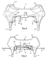
- Figure 1 shows a part 1 of a vehicle chassis or subframe to which there is attached a movable member or bed 2 which is itself secured in a generally non-movable manner to a steering control member such as a steering rack 3, including steering control means in the form of track rod ends 6, by means of compliant mounts 5 carried on the bed.
- the movable bed 2 is mounted on the vehicle chassis or subframe in a manner which permits repeated limited lateral translational movement in the axial direction of the steering rack by a few millimetres so as to produce an adjustment superimposed on the steering angle selected by the driver of the vehicle. Lateral movement of the bed 2 can be determined by any convenient means such as electrical or hydraulic drives.
- Control of the movement of the bed 2 is effected by a control unit 4 which may incorporate a microprocessor and which receives inputs from transducers positioned around the vehicle and measuring, for example, the steering angle selected by the driver, lateral and yaw accelerations of the vehicle, yaw rate, vehicle speed and data relating to the suspension system of the vehicle.
- a control unit 4 which may incorporate a microprocessor and which receives inputs from transducers positioned around the vehicle and measuring, for example, the steering angle selected by the driver, lateral and yaw accelerations of the vehicle, yaw rate, vehicle speed and data relating to the suspension system of the vehicle.
- the steering effect of the lateral movement of the bed 2 is small relative to the steering effect that can be produced by the driver of the vehicle. This ensures that should the controller 4 cease to function or develop a fault the driver will be able to retain control of the vehicle.
- a particular advantage of the present arrangement is that the control system is separate from the driver's input and it not incorporated, for example, in any power steering apparatus.
- the steer angle adjusting apparatus shown in Figures 2 to 4 is mounted on a front subframe 11 of a vehicle which is mounted to a vehicle body (not shown) by means of mounting points 12.
- a front subframe 11 of a vehicle which is mounted to a vehicle body (not shown) by means of mounting points 12.
- two compliant mounts 13 Secured to the subframe 11 in a non-movable manner are two compliant mounts 13 which take the form of rubber bushes which exhibit high radial stiffness (low compliance) combined with low axial stiffness (high compliance).
- An alternative mounting system could incorporate a linear slide arrangement.
- FIG 4 shows a steering control member in the form of a steering rack 14 mounted in the compliant mounts 13 so as to be movable axially as a result of axial compliance of the mounts but substantially immovable radially.
- Steering rack 14 is conventional and in the illustrated emboidment is a power steering assembly.
- a control unit 15 Also mounted in a non-movable manner on the subframe 11 are a control unit 15 and a proportional valve and cylinder assembly 16 which operates to move an operating rod 17 backwards and forwards in an axial direction.
- the valve and cylinder assembly 16 incorporates a fail-safe device (not shown) which inhibits axial movement of the operating rod 17 in the event of any failure in the steer angle adjusting apparatus.
- Operating rod 17 is connected to steering rack 14 by connecting member 18 which incorporates a compliant mount 19 to reduce harshness in the effect of the steer angle adjusting apparatus, but having a lower axial compliance than the mounts 13.
- Operating rod 17 is able to superimpose an additional movement of about 15mm amplitude on the movement normally available at track rod ends 21.
- Control of the valve and cylinder assembly by the control unit 15 is determined as a result of transducers, such as transducer 20, positioned around the vehicle as described above.
- the apparatus shown in the figures can be applied to either the front wheels or the rear wheels of the vehicle, or can be applied to both the front and rear wheels.
- the provision of active steering control on both the front and rear wheels can also result in reduced response to lateral wind gusts and can improve handling when adhesion limits are reached on one or more of the wheels.
Landscapes
- Engineering & Computer Science (AREA)
- Chemical & Material Sciences (AREA)
- Combustion & Propulsion (AREA)
- Transportation (AREA)
- Mechanical Engineering (AREA)
- Physics & Mathematics (AREA)
- Mathematical Physics (AREA)
- Theoretical Computer Science (AREA)
- Steering Control In Accordance With Driving Conditions (AREA)
- Steering-Linkage Mechanisms And Four-Wheel Steering (AREA)
Applications Claiming Priority (2)
| Application Number | Priority Date | Filing Date | Title |
|---|---|---|---|
| GB888816857A GB8816857D0 (en) | 1988-07-15 | 1988-07-15 | Steer angle adjusting apparatus for vehicle |
| GB8816857 | 1988-07-15 |
Publications (2)
| Publication Number | Publication Date |
|---|---|
| EP0351146A2 true EP0351146A2 (fr) | 1990-01-17 |
| EP0351146A3 EP0351146A3 (fr) | 1990-10-31 |
Family
ID=10640498
Family Applications (1)
| Application Number | Title | Priority Date | Filing Date |
|---|---|---|---|
| EP19890306911 Withdrawn EP0351146A3 (fr) | 1988-07-15 | 1989-07-07 | Ajustement de l'angle de braquage pour véhicules |
Country Status (3)
| Country | Link |
|---|---|
| EP (1) | EP0351146A3 (fr) |
| JP (1) | JPH02216370A (fr) |
| GB (1) | GB8816857D0 (fr) |
Cited By (7)
| Publication number | Priority date | Publication date | Assignee | Title |
|---|---|---|---|---|
| FR2657834A1 (fr) * | 1990-02-06 | 1991-08-09 | Aisin Seiki | Dispositif de commande de la direction d'un vehicule. |
| FR2674811A1 (fr) * | 1991-04-03 | 1992-10-09 | Renault | Dispositif de commande de braquage de roues et son procede de mise en óoeuvre. |
| US5261503A (en) * | 1990-07-11 | 1993-11-16 | Aisin Seiki Kabushiki Kaisha | Adaptive steering control system |
| US5373911A (en) * | 1991-12-18 | 1994-12-20 | Aisin Seiki Kabushiki Kaisha | Vehicle guidance control system |
| DE4414020C1 (de) * | 1994-04-22 | 1995-06-08 | Daimler Benz Ag | Lagerung einer Zahnstangenlenkung |
| FR2773129A1 (fr) * | 1997-12-31 | 1999-07-02 | Renault | Systeme de correction automatique de la trajectoire d'un vehicule soumis a des perturbations de la chaussee ou du vent lateral |
| DE102004011593B4 (de) * | 2004-03-10 | 2008-04-30 | Audi Ag | Lenkvorrichtung für Kraftfahrzeuge |
Family Cites Families (4)
| Publication number | Priority date | Publication date | Assignee | Title |
|---|---|---|---|---|
| US4144948A (en) * | 1978-05-11 | 1979-03-20 | Sergay Dimitry B | Power steering system |
| JPS58214457A (ja) * | 1982-06-07 | 1983-12-13 | Nissan Motor Co Ltd | 前輪補助操舵装置 |
| JPS6025576U (ja) * | 1983-07-29 | 1985-02-21 | 日産自動車株式会社 | ステアリング装置 |
| GB2186245B (en) * | 1986-02-12 | 1989-06-07 | Honda Motor Co Ltd | Steering gear box mounts |
-
1988
- 1988-07-15 GB GB888816857A patent/GB8816857D0/en active Pending
-
1989
- 1989-07-07 EP EP19890306911 patent/EP0351146A3/fr not_active Withdrawn
- 1989-07-14 JP JP18239189A patent/JPH02216370A/ja active Pending
Cited By (10)
| Publication number | Priority date | Publication date | Assignee | Title |
|---|---|---|---|---|
| US5159553A (en) * | 1988-09-13 | 1992-10-27 | Aisin Seiki Kabushiki Kaisha | Steering control apparatus |
| FR2657834A1 (fr) * | 1990-02-06 | 1991-08-09 | Aisin Seiki | Dispositif de commande de la direction d'un vehicule. |
| US5261503A (en) * | 1990-07-11 | 1993-11-16 | Aisin Seiki Kabushiki Kaisha | Adaptive steering control system |
| FR2674811A1 (fr) * | 1991-04-03 | 1992-10-09 | Renault | Dispositif de commande de braquage de roues et son procede de mise en óoeuvre. |
| US5373911A (en) * | 1991-12-18 | 1994-12-20 | Aisin Seiki Kabushiki Kaisha | Vehicle guidance control system |
| DE4414020C1 (de) * | 1994-04-22 | 1995-06-08 | Daimler Benz Ag | Lagerung einer Zahnstangenlenkung |
| US5597049A (en) * | 1994-04-22 | 1997-01-28 | Mercedes-Benz Ag | Rack-and-pinion steering system mounting |
| FR2773129A1 (fr) * | 1997-12-31 | 1999-07-02 | Renault | Systeme de correction automatique de la trajectoire d'un vehicule soumis a des perturbations de la chaussee ou du vent lateral |
| EP0927678A1 (fr) * | 1997-12-31 | 1999-07-07 | Renault | Système de correction automatique de la trajectoire d'un véhicule soumis à des pertubations de la chaussée ou du vent latéral |
| DE102004011593B4 (de) * | 2004-03-10 | 2008-04-30 | Audi Ag | Lenkvorrichtung für Kraftfahrzeuge |
Also Published As
| Publication number | Publication date |
|---|---|
| JPH02216370A (ja) | 1990-08-29 |
| GB8816857D0 (en) | 1988-08-17 |
| EP0351146A3 (fr) | 1990-10-31 |
Similar Documents
| Publication | Publication Date | Title |
|---|---|---|
| EP2084024B1 (fr) | Ensemble de suspension de roue, et vehicule a moteur | |
| EP0089631B1 (fr) | Système de contrôle de direction pour véhicule automobile ou équivalent | |
| US5292149A (en) | Arrangement for the active adjustment of a motor vehicle wheel | |
| US9994249B2 (en) | Vehicle, and method for steering control of same | |
| US6154696A (en) | Steering control system for controlling torque steer | |
| US4828279A (en) | Wheel suspension for the driven rear wheels of motor vehicles | |
| CN103415406B (zh) | 汽车及转舵轮的转舵控制方法 | |
| US4457537A (en) | Independent wheel suspension | |
| CN102198781B (zh) | 活动式后轮悬架 | |
| JPH02144205A (ja) | 後輪操舵車両の後輪懸架装置 | |
| EP0351146A2 (fr) | Ajustement de l'angle de braquage pour véhicules | |
| JPH0344027B2 (fr) | ||
| US4842295A (en) | Vehicle wheel suspension | |
| EP0102078B1 (fr) | Voiture pour entraînement au dérapage | |
| US4840393A (en) | Wheel suspension for steerable rear wheel on motor vehicles equipped with front wheel steering especially passenger vehicle | |
| JP3076541B2 (ja) | 操向車輪制御構造 | |
| JP2841774B2 (ja) | 車両用キャスタ角制御装置 | |
| US5823288A (en) | Controllable slide car | |
| JPS5923775A (ja) | 後輪補助操舵装置 | |
| JP3209467B2 (ja) | 自動車用後輪サスペンション装置 | |
| JP2580851B2 (ja) | 車両用キャスタ角制御装置 | |
| JPS5970258A (ja) | 後輪補助操舵装置 | |
| JPH052552B2 (fr) | ||
| EP0468567A1 (fr) | Véhicule pourvu d'un essieu rigide dirigeable | |
| JP2570479B2 (ja) | 車両用キャスタ角制御装置 |
Legal Events
| Date | Code | Title | Description |
|---|---|---|---|
| PUAI | Public reference made under article 153(3) epc to a published international application that has entered the european phase |
Free format text: ORIGINAL CODE: 0009012 |
|
| AK | Designated contracting states |
Kind code of ref document: A2 Designated state(s): DE FR GB IT SE |
|
| PUAL | Search report despatched |
Free format text: ORIGINAL CODE: 0009013 |
|
| AK | Designated contracting states |
Kind code of ref document: A3 Designated state(s): DE FR GB IT SE |
|
| STAA | Information on the status of an ep patent application or granted ep patent |
Free format text: STATUS: THE APPLICATION IS DEEMED TO BE WITHDRAWN |
|
| 18D | Application deemed to be withdrawn |
Effective date: 19910503 |