EP0351340A1 - Beschlag für Kippfenster - Google Patents
Beschlag für Kippfenster Download PDFInfo
- Publication number
- EP0351340A1 EP0351340A1 EP89440063A EP89440063A EP0351340A1 EP 0351340 A1 EP0351340 A1 EP 0351340A1 EP 89440063 A EP89440063 A EP 89440063A EP 89440063 A EP89440063 A EP 89440063A EP 0351340 A1 EP0351340 A1 EP 0351340A1
- Authority
- EP
- European Patent Office
- Prior art keywords
- frame
- opening
- support
- opening frame
- sleeping
- Prior art date
- Legal status (The legal status is an assumption and is not a legal conclusion. Google has not performed a legal analysis and makes no representation as to the accuracy of the status listed.)
- Withdrawn
Links
- 238000006073 displacement reaction Methods 0.000 claims description 16
- 230000000694 effects Effects 0.000 claims description 7
- 230000005484 gravity Effects 0.000 claims description 2
- 210000003127 knee Anatomy 0.000 claims description 2
- 230000000903 blocking effect Effects 0.000 claims 1
- 230000002028 premature Effects 0.000 abstract 1
- 230000002093 peripheral effect Effects 0.000 description 8
- 230000006835 compression Effects 0.000 description 6
- 238000007906 compression Methods 0.000 description 6
- 230000001419 dependent effect Effects 0.000 description 3
- 239000000470 constituent Substances 0.000 description 2
- 230000002250 progressing effect Effects 0.000 description 2
- 238000007665 sagging Methods 0.000 description 2
- 241001080024 Telles Species 0.000 description 1
- 230000006837 decompression Effects 0.000 description 1
- 238000003754 machining Methods 0.000 description 1
- 238000012423 maintenance Methods 0.000 description 1
- 239000000463 material Substances 0.000 description 1
- 239000002184 metal Substances 0.000 description 1
- 238000000926 separation method Methods 0.000 description 1
- 239000002023 wood Substances 0.000 description 1
Images


Classifications
-
- E—FIXED CONSTRUCTIONS
- E05—LOCKS; KEYS; WINDOW OR DOOR FITTINGS; SAFES
- E05D—HINGES OR SUSPENSION DEVICES FOR DOORS, WINDOWS OR WINGS
- E05D15/00—Suspension arrangements for wings
- E05D15/40—Suspension arrangements for wings supported on arms movable in vertical planes
- E05D15/46—Suspension arrangements for wings supported on arms movable in vertical planes with two pairs of pivoted arms
- E05D15/466—Suspension arrangements for wings supported on arms movable in vertical planes with two pairs of pivoted arms specially adapted for windows
-
- E—FIXED CONSTRUCTIONS
- E05—LOCKS; KEYS; WINDOW OR DOOR FITTINGS; SAFES
- E05D—HINGES OR SUSPENSION DEVICES FOR DOORS, WINDOWS OR WINGS
- E05D15/00—Suspension arrangements for wings
- E05D15/40—Suspension arrangements for wings supported on arms movable in vertical planes
- E05D15/44—Suspension arrangements for wings supported on arms movable in vertical planes with pivoted arms and vertically-sliding guides
-
- E—FIXED CONSTRUCTIONS
- E05—LOCKS; KEYS; WINDOW OR DOOR FITTINGS; SAFES
- E05Y—INDEXING SCHEME ASSOCIATED WITH SUBCLASSES E05D AND E05F, RELATING TO CONSTRUCTION ELEMENTS, ELECTRIC CONTROL, POWER SUPPLY, POWER SIGNAL OR TRANSMISSION, USER INTERFACES, MOUNTING OR COUPLING, DETAILS, ACCESSORIES, AUXILIARY OPERATIONS NOT OTHERWISE PROVIDED FOR, APPLICATION THEREOF
- E05Y2900/00—Application of doors, windows, wings or fittings thereof
- E05Y2900/10—Application of doors, windows, wings or fittings thereof for buildings or parts thereof
- E05Y2900/13—Type of wing
- E05Y2900/148—Windows
Definitions
- the invention relates to articulation fittings for a chassis opening with partial overlap of the sleeping frame and with Italian opening, comprising, on the one hand, lower compass arms and, on the other hand, articulation elements. upper likely to project outward, at the opening, the upper cross member of said opening frame.
- This invention will find, more particularly, its application in the field of building hardware.
- these articulation fittings are composed, on the one hand, of two compass arms arranged on either side of the window and connected, at their upper end, to the middle part of the lateral uprights of the opening frame and, in their lower end, at the side uprights and near the lower corner of the frame.
- articulation fittings also comprise, on the other hand, upper articulation elements comprising a ramp keeper fixed in the upper part of the lateral uprights of the fixed frame.
- a roller integral with a link the ends of which are fixed by means of articulations, on the one hand, to the opening frame and, on the other hand, to a connecting piece mounted sliding in a slide. secured to the sleeping frame.
- the ramp strike breaks down into a groove, of curvilinear shape concentric with the axis of rotation of the rod, and arranged in the aforementioned connecting piece.
- This curvilinear groove abuts, in its upper part a vertical oblong light extending upwards from the sleeping frame.
- Such a projection towards the outside of the opening frame is essential in the context of articulation fittings embedded in rebates of the door or window. Indeed, under these conditions, the fictitious axis of rotation of the opening frame is necessarily disposed below its upper edge. Thus, in the absence of a suitable device, this upper edge of the opening frame comes to cooperate, at the time of opening, with the rebate of the upper cross member of the fixed frame and limits or prevents the rotation of said opening frame.
- This compressible seal provides, in fact, only a partial solution to the problem because its effectiveness is seen to decrease rapidly during use.
- the upper cross member of the opening frame performs, initially, a rotation followed by a vertical displacement before taking a trajectory with a horizontal component.
- the seal is compressed and then slides along the upper cross member of the frame before moving away from it.
- the document GB-A-2,176,533 reveals a device which only has the effect of accentuating the action already printed on the opening element by means of traditional hinge fittings for doors or windows opening at the opening.
- articulation fittings have the function of ensuring projection towards the outside and the offset, in a direction parallel to the plane of the door or window of the rear upright of the opening during the pivoting of the latter. around a vertical axis.
- this projection towards the outside, relative to the sleeping frame, of the rear upright of the opening occurs only beyond a particularly large angle of rotation of the latter, rotation during which the joint d
- the above seal is highly stressed. This drawback is found despite the presence of the device of the prior document since its action is necessarily limited by the hinge fittings which in fact constitute the only connecting elements between the door and the frame.
- the present invention aims to remedy these drawbacks.
- the invention as characterized in the claims solves the problem of creating articulation fittings for chassis opening to partial covering of the sleeping frame and with Italian opening, comprising on the one hand, lower compass arms and on the other hand, upper articulation elements capable of projecting, towards the outside, at the opening the upper cross member of said opening frame, these articulation fittings comprising means for imparting, at the very start of opening, a trajectory with a vertical component to said opening frame while imparting to the upper cross member of the latter a movement with a horizontal component.
- the present invention relates to articulation fittings 1 for opening frame to the Italian 2.
- these articulation fittings 1 as shown in Figures 1, 2, 5, 6 and 21 have lower compass arms 3 arranged in rebates 4 of the lateral uprights 5, 6 respectively of the opening frames 2 and of the frame 7.
- a lower compass arm 3 is connected, by means of articulation means 8, 9, on the one hand, substantially, in the middle part of a lateral upright 5 of the opening frame 2 and, on the other hand, to the corresponding lateral upright 6 of the sleeping frame 7.
- This connection of the lower compass arms 3 of said sleeping frame 7 is preferably located near the lower angles 10, 11 of the latter.
- these lower compass arms 3 The function of these lower compass arms 3 is to cause the opening frame 2 to pivot outwards while giving the latter a displacement with a vertical component. They also ensure that the opening frame 2 is held in a half-open position, at a variable angle, relative to the sleeping frame 7.
- the articulation fittings 1 are completed by upper articulation elements 12, connecting, at the level of the lateral uprights 5 and close to the upper cross member 13, the opening frame 2 to the lateral uprights 6 of the sleeping frame 7. They thus favor , the rotation, around a horizontal axis, of the opening frame 2, while accompanying the latter in its vertical displacements controlled by the lower compass arms 3.
- the upper articulation elements 12 also provide the projection, towards the outside, of the sleeping frame 7, of this opening frame 2, so that its upper cross member 13 does not interfere with the opening of the window or the like. .
- Such an outward projection finds, in particular, its advantage in the case of an opening frame 2 partially covering the sleeping frame 7 as shown in FIG. 21.
- These opening frames 2 are then provided on their periphery 14, d 'an overlapping lip 15 fitted with a seal 16 coming in the closed position, applied to the external face 17 of the frame 7.
- the hinge fittings 1 are provided with means 18 capable of imparting, at the very start of window opening, a component trajectory vertical to said opening frame 2 while printing, on the upper crosspiece of the latter, a horizontal displacement.
- these means 18 consist, on the one hand, of articulated lower compass arms 3 allowing, beyond an opening angle reduced to the minimum, a sagging, under the effect of gravity, of the opening frame 2 relative to the sleeping frame 7. This subsidence causes, simultaneously, the release of the upper cross member 13 of said opening frame 2 relative to the upper cross member 19 of this sleeping frame 7 thanks to specific upper articulation elements 12.
- these means 18 have the effect of obtaining a trajectory of the connection point 20 of the lower compass arms 3 to the opening frame 2, the derivative of which tends towards infinity during closing, this derivative being equal to zero in the frame of known, non-articulated compass arms.
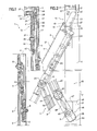
- the upper articulation elements 12 consist, according to a first embodiment, visible in FIGS. 1 to 4, of a keeper with a ramp arranged, in rebates, on a lateral upright 6 of the frame 7 in the upper corner 22 of the latter.
- This ramp keeper 21 has an oblique groove 23 orienting, in its upper part 24, towards the interior of the dwelling and leading, at its lower end 25 to a vertical groove 26 whose length will depend on the angle maximum opening that should be given to the opening frame.
- a roller 28 integral with the upper end 29 of a connecting piece 30 cooperating with a support 31 fixed in rebates 32 of the lateral upright 5 of the opening frame 2.
- the connecting piece 30 essentially serves as an adjusting member for said opening frame 2 relative to the sleeping frame 7 in a direction perpendicular to the latter.
- said connecting piece 30 is pivotally mounted, in its middle 33, on said support 31 and comprises, in its lower part 34, an opening 35 of oblong shape serving as passage for a fixing member 36 and determining the range possible adjustment.
- the support 31 having, on this occasion, a square shape and covering the upper angle 37 of the opening frame 2. More precisely , the horizontal wing 38 of this support 31 includes adjustment means 39 cooperating with the upper edge 40 of the upper cross member 13 of said opening frame 2. These adjustment means 30 thus determine the height position of the vertical wing 41 of this support 31 on the lateral upright 5.
- this support 31 is possible, these being essentially determined depending on the structure and materials of the window.
- the support 31 will be designed differently depending on whether the opening frame 2 and the sleeping frame 7 are made of wood or of metal or plastic profile.
- fixing means 42 ensuring the connection of this vertical wing 41 of the support 31 to the lateral upright 5 of the opening frame 2.
- they will be determined so as to avoid any machining in the event of profiled structure.
- FIGS. 1, 2, 5, 6 and 17 to 20 show, according to different embodiments, a lower compass arm 3 which, according to the invention, is articulated to give the opening frame 2 a vertical displacement from the opening. More specifically, have been shown in Figures 17 to 20, the lower section 43 of the lower compass arm 3 and its connection to the fixed frame 7 via the hinge means 9. As for the hinge means 8 connecting the upper section 44 to the lateral upright 5 of the opening frame 2, they are more particularly visible, in FIGS. 1, 2, 5 and 6.
- the articulation 45 connecting said lower section 43 to the upper section 44 of the lower compass arm 3 is provided with a stop member capable of limiting the angle formed by these. Furthermore, the articulation means 9, ensuring the connection at the level of the sleeping frame 7 of said lower compass arm 3 are provided with abutment means 46 capable of limiting the angular displacement executed by the lower section 43 during opening.
- Such abutment means 46 not only determine the maximum pivoting angle that it is possible to give to the opening frame 2, but also and above all, allow the lower compass arms 3 to play a supporting role. In fact, these compensate, in part, for the load formed by said opening frame 2 and which, if not, would be supported, in full, by the upper articulation elements 12.
- the articulation means 9, connecting the lower section 43 of a lower compass arm 3 to a lateral upright 6 of the sleeping frame 7, comprise a support element 47, fixed in rabbets 48 of said lateral upright 6 and on which the lower part 49 of said lower section 43 is pivotally mounted.
- This support element 47 is provided, on its rear vertical edge 50, with a flange 51 in which is milled a cutout 52 constituting the stop means 46. More precisely, in the cutout 52 is inserted, in the open position, the lower end 53 of said lower section 43 limiting the latter in angular displacement.
- the operation of the articulation fittings designed according to this first embodiment is as follows: - from the opening command by means of a locking fitting, not shown, the simple decompression of the peripheral seal 16 pushes the opening frame 2 of the frame 7 causing the opening of said opening frame 2 accompanied by a displacement of the roller 28 of the upper articulation element 12 in the oblique groove 23 this results in immediate detachment of the upper cross member 13 of said opening frame 2 relative to the upper cross member 19 corresponding to the sleeping frame 7; - by progressing in the opening direction of the window, the opening frame 2 begins to rotate around a horizontal axis materialized by the rollers 28, the latter coming, simultaneously, to slide along the oblique groove 23 before evolving in the vertical groove 26 and reach the lower end 54 of the latter.
- the opening frame 2 is then in its maximum open position; -
- the traction exerted by the user on the opening frame 2 so as to close it causes, under the impulse of the lower compass arms 3, the rise of the rollers 28 corresponding to the articulation elements upper 12, in ramp strikes 21; - at the end of locking, receiving strikes (not shown in the figures), fixed in rebates 32 of the lateral uprights 5 of the opening frame 2 cooperate with the knee 56 of the lower compass arms 3 so as to cause the section to be realigned lower 43 and upper 44 of these.
- these articulation fittings 1, in accordance with the invention and executed according to this first embodiment can have a drawback which consists of a relatively large space requirement in rebates of the lateral uprights 5 and 6 respectively of the opening frame 2 and the frame 7.
- the amplitude of the displacement, in a horizontal direction, imparted to said opening frame 2 is dependent on the length and the angle, relative to the horizontal, of the oblique groove 23.
- these parameters are themselves dependent on the width 57 of the keeper with ramp 21 and, finally, on the space available in rebates 48 of the lateral uprights 6 of the frame 7.
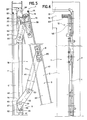
- the second embodiment of the articulation fittings 1, in accordance with the invention and shown in FIGS. 5 to 16, aims to solve the aforementioned problem by proposing upper articulation elements 12 and articulation means 9 connecting the lower compass arm 3 to the sleeping frame 7 of smaller size and whose effectiveness is not dependent on any dimensional condition of the window structures.
- the upper articulation elements 12 comprise a support on the opening 58 in the form of a square coming to cover the upper angle 37 of the opening frame 2 and the horizontal wing 59 of which is provided with means of adjustment 60. These allow the positioning of the opening frame 2 in a vertical direction on the sleeping frame 7. At the upper end 61 of the vertical wing 62 of this support on opening 58 is articulated one of the ends 63 d 'a link 64 connecting said opening frame 2 to the sleeping frame 7.
- the latter is equipped at the upper end of the lateral uprights 6, of a support on the frame 65 comprising, in its lower part 66, a light in form of a comma 67, in which is engaged a roller 68 integral with the opposite end 69 of the rod 64.
- the actually called projection of the opening frame 2 towards the outside occurs simultaneously with the pivoting imparted to the latter during the opening and this, by means of suitable means 70. It will be noted, for this purpose, that the amplitude of the horizontal displacement imparted to this opening frame 2 is proportional to the angle of rotation printed on the latter.
- these means 70 are constituted by a secondary arm 71 pivotally mounted in its middle 72 on the link 64, slightly below the articulation 73 connecting the latter to the support on the opening 58.
- this secondary arm 71 cooperates, its ends 74, 75 respectively, with the support on the frame 65 and the said support on the opening 58. More precisely, the latter is provided with a boss 76 provided with a stud 77 engaged in an oblong slot 78 fitted at the end lower 75 of the secondary arm 71.
- This lower end 75 is provided in a curvilinear shape so as to reduce the dimensions of this secondary arm 71 in rebates of the window.
- this lower end 75 like the oblong opening 78 which is produced therein, can be kept strictly rectilinear without such an arrangement being contrary to the proper functioning of the articulation fittings 1.
- the above-mentioned boss 76 has, essentially, the function of compensating for the thickness of said link 64. It constitutes, in addition, support for the secondary arm 71 and promotes the proper functioning of the upper articulation element 12. Furthermore, so as to reduce the overall size of this articulation element 12, the rod 64 has, in return , a cutout 79 used to accommodate the boss 76 in the closed position of the window.
- this secondary arm 71 As for the upper end 74 of this secondary arm 71, it has an extension 80 forming a lever arm and cooperating, at its free end 81, with a support ramp 82 arranged on the support on the frame 65.
- the opening of the window causes, initially, and as already mentioned above, the sliding of the roller 68 in the slot 67. Then, the angular displacement of the opening frame 2 generates the rotation of the secondary arm 71 via the stud 77.
- the extension 80 cooperating with the support ramp 82 gives an angular displacement to the rod 64 which pushes said opening frame 2 and, in particular, its cross member upper 13 outside of the sleeping frame 7.
- the profile of this support ramp 82 will be determined as a function of the amplitude of the horizontal displacement which it is necessary to impart to the opening frame 2. The fact of imparting to it a concave shape makes it possible to obtain a certain proportionality between the horizontal displacement and the pivoting angle of the opening frame 2.
- the extension 80 of the secondary arm 71 also serves, on the one hand, as a means for compressing the peripheral seal 16 when the window is closed and, on the other hand part, of the frame locking member opening 2 against the standing frame 7.
- the support on the frame 65 is provided, at its upper end 83, with a keeper 84 constituted, substantially, by an extension 85 of the support ramp 82 and a boss 86 arranged on the opposite side 87 to the latter.
- this keeper 84 the opening of which widens, progressively engages the extension 80 of the secondary arm 71 during the closing of the opening frame 2.
- the end free 81 of this extension 80 cooperates, more precisely, with the guide ramp 88 formed by the boss 86.
- the progression of this free end 81 on said guide ramp 88 contributes, like the evolution of the roller 68 in the lumen 67, to the compression of the peripheral seal 16.
- the return 89 of said comma-shaped lumen 67 aims to lock this closed position of the chassis opening 2 by opposing the downward movement of the roller 68.
- the compression intensity of the peripheral seal 16 is determined, in particular, in the upper part of the window, as a function of the position of the support on the opening 58 on the lateral upright 5 of the opening frame 2. This position is adjustable to using an eccentric 90 or equivalent means disposed on said support on opening 58.
- this upper articulation element 12 shape of the constituent parts of this upper articulation element 12 and, in particular, their respective thickness are determined so as to avoid any notching, both in the lateral uprights 5 of the opening frame 2 and in the sleeping frame 7.
- Said support element 91 further comprises the abutment means 46 limiting the angle of rotation of this lower section 43.
- these abutment means 46 are constituted, essentially, by a flange 92 arranged on the vertical edge rear 93 of the support element 91 and against which abuts the lower end 53 of said lower section 43, in the open position of the window. More precisely, this lower section 43 is bevelled at this lower end 53 and on its rear edge 94 so as to define an inclined edge 95 bearing against the flange 92 in the open position of the opening frame 2.
- Such a morphology of the means hinge 9 allows, in fact, to significantly reduce their overall size regardless of the position of the window.
- adjustment means 96 to ensure the correct positioning of the support element 91 on the lateral upright 6 of the fixed frame 7 and, in a direction perpendicular to the plane of the latter.
- Such adjustment means 96 are essential for determining the compression imparted to the peripheral seal 16 when the window is closed.
- adjustment means 96 can be used in the context of the first embodiment detailed above in the description and shown in FIGS. 1 and 2.
- this support element 91 As regards the articulated mounting of the lower part 49 of the lower section 43 on this support element 91, it is preferably in the form of an axis 97 made integral with the support element 91, this axis 97 passing through an opening 98 machined in the lower part 49 of said lower section 43.
- a flange or any other equivalent element, integral with the free end of this axis 97, will advantageously oppose any disengagement of the lower compass arm 3.
- this axis 97 is housed in a recess 99 machined in said support element 91, and communicating with an orifice 100 used for the passage of a fixing member such as a screw or rivet.
- the recess 99 is substantially off-center with respect to the orifice 100 so as to prevent, after assembly, any rotation of the axis 97 under the action of the incessant pivotings of the lower section 43.
Landscapes
- Engineering & Computer Science (AREA)
- Mechanical Engineering (AREA)
- Wing Frames And Configurations (AREA)
- Orthopedics, Nursing, And Contraception (AREA)
- Hinges (AREA)
Applications Claiming Priority (2)
| Application Number | Priority Date | Filing Date | Title |
|---|---|---|---|
| FR8809658 | 1988-07-12 | ||
| FR8809658A FR2634248B1 (fr) | 1988-07-12 | 1988-07-12 | Ferrures d'articulation pour chassis ouvrant a l'italienne |
Publications (1)
| Publication Number | Publication Date |
|---|---|
| EP0351340A1 true EP0351340A1 (de) | 1990-01-17 |
Family
ID=9368491
Family Applications (1)
| Application Number | Title | Priority Date | Filing Date |
|---|---|---|---|
| EP89440063A Withdrawn EP0351340A1 (de) | 1988-07-12 | 1989-06-28 | Beschlag für Kippfenster |
Country Status (4)
| Country | Link |
|---|---|
| US (1) | US4996794A (de) |
| EP (1) | EP0351340A1 (de) |
| JP (1) | JPH02153183A (de) |
| FR (1) | FR2634248B1 (de) |
Cited By (1)
| Publication number | Priority date | Publication date | Assignee | Title |
|---|---|---|---|---|
| EP2157265A1 (de) * | 2008-08-21 | 2010-02-24 | VKR Holding A/S | Fensterscharnieranordnung und Verfahren zum Montieren eines Flügels an einem Rahmen |
Families Citing this family (7)
| Publication number | Priority date | Publication date | Assignee | Title |
|---|---|---|---|---|
| GB2325961B (en) * | 1997-06-06 | 2002-02-13 | Euromond Ltd | Closures incorporating friction stays |
| DE10300847A1 (de) * | 2003-01-10 | 2004-07-22 | SCHÜCO International KG | Beschlagseinheit für ein Fenster oder eine Tür |
| JP4363303B2 (ja) * | 2004-10-21 | 2009-11-11 | ブラザー工業株式会社 | ヒンジ装置、そのヒンジ装置を備えた自動原稿搬送装置、読取ユニット及び画像形成装置 |
| JP5104027B2 (ja) * | 2007-05-18 | 2012-12-19 | オイレスEco株式会社 | 自然換気装置 |
| WO2010088906A1 (en) * | 2009-02-03 | 2010-08-12 | Vkr Holding A/S | A method for making a window and an opening window |
| JP6868441B2 (ja) * | 2017-03-31 | 2021-05-12 | 三協立山株式会社 | 建具 |
| CN112590427B (zh) * | 2020-12-08 | 2022-07-08 | 南京涵曦月自动化科技有限公司 | 一种职业技能培训用辅助教具 |
Citations (6)
| Publication number | Priority date | Publication date | Assignee | Title |
|---|---|---|---|---|
| US3797169A (en) * | 1972-10-19 | 1974-03-19 | Truth Inc | Window hinge |
| GB2010368A (en) * | 1977-10-07 | 1979-06-27 | Code Designs | Improvements Relating to Windows |
| GB2047309A (en) * | 1979-04-21 | 1980-11-26 | Securistyle Ltd | Improvements in friction supporting stays for windows |
| EP0141000A2 (de) * | 1983-10-07 | 1985-05-15 | Sankyo Aluminium Industry Company Limited | Umkehrfenster |
| FR2554860A1 (fr) * | 1983-11-10 | 1985-05-17 | Bezault Sa | Dispositif perfectionne de ferrage pour chassis ouvrant a l'italienne |
| GB2176533A (en) * | 1985-06-14 | 1986-12-31 | Securistyle Ltd | Friction supporting stay |
Family Cites Families (5)
| Publication number | Priority date | Publication date | Assignee | Title |
|---|---|---|---|---|
| CH157866A (de) * | 1931-04-07 | 1932-10-31 | Wagner Kurt | Nach aussen schwenkbares Fenster. |
| GB541337A (en) * | 1940-05-18 | 1941-11-24 | Percy Lionel Heyne | An improved mounting and fixing of sashes to window frames |
| US2797917A (en) * | 1955-08-18 | 1957-07-02 | Lickteig Sr | Link arrangement for window actuator |
| US3101135A (en) * | 1960-09-14 | 1963-08-20 | Amarlite Corp | Window structure |
| GB1471700A (en) * | 1973-06-22 | 1977-04-27 | Anvar | Window |
-
1988
- 1988-07-12 FR FR8809658A patent/FR2634248B1/fr not_active Expired - Fee Related
-
1989
- 1989-06-28 EP EP89440063A patent/EP0351340A1/de not_active Withdrawn
- 1989-07-06 US US07/376,034 patent/US4996794A/en not_active Expired - Fee Related
- 1989-07-11 JP JP1177279A patent/JPH02153183A/ja active Pending
Patent Citations (6)
| Publication number | Priority date | Publication date | Assignee | Title |
|---|---|---|---|---|
| US3797169A (en) * | 1972-10-19 | 1974-03-19 | Truth Inc | Window hinge |
| GB2010368A (en) * | 1977-10-07 | 1979-06-27 | Code Designs | Improvements Relating to Windows |
| GB2047309A (en) * | 1979-04-21 | 1980-11-26 | Securistyle Ltd | Improvements in friction supporting stays for windows |
| EP0141000A2 (de) * | 1983-10-07 | 1985-05-15 | Sankyo Aluminium Industry Company Limited | Umkehrfenster |
| FR2554860A1 (fr) * | 1983-11-10 | 1985-05-17 | Bezault Sa | Dispositif perfectionne de ferrage pour chassis ouvrant a l'italienne |
| GB2176533A (en) * | 1985-06-14 | 1986-12-31 | Securistyle Ltd | Friction supporting stay |
Cited By (1)
| Publication number | Priority date | Publication date | Assignee | Title |
|---|---|---|---|---|
| EP2157265A1 (de) * | 2008-08-21 | 2010-02-24 | VKR Holding A/S | Fensterscharnieranordnung und Verfahren zum Montieren eines Flügels an einem Rahmen |
Also Published As
| Publication number | Publication date |
|---|---|
| FR2634248B1 (fr) | 1994-03-11 |
| FR2634248A1 (fr) | 1990-01-19 |
| US4996794A (en) | 1991-03-05 |
| JPH02153183A (ja) | 1990-06-12 |
Similar Documents
| Publication | Publication Date | Title |
|---|---|---|
| EP0290362B1 (de) | Drehbeschlag eines Drehkippflügels einer Tür eines Fensters oder von ähnlichem | |
| EP0364379A1 (de) | Dreh-Kipp-Beschlag für Türen, Fenster oder dergleichen in der Fensterfüge angeordnet | |
| EP0436452A2 (de) | Tür- oder Fensterbeschlag mit Mitteln zum Halten der Flügel in geöffnetem Zustand | |
| EP0351340A1 (de) | Beschlag für Kippfenster | |
| CA1297135C (fr) | Ferrure de verrouillage notamment pour ouvrant coulissant | |
| EP1722052A1 (de) | Schloss für eine Eingangstür in einem Sektionaltor, insbesondere für Garagen | |
| EP4190998A1 (de) | Vorrichtung zum halten eines flügels | |
| FR2740504A1 (fr) | Dispositif de maintien d'un ouvrant dans une position entrebaillee | |
| EP0467728A1 (de) | Beschlag für einen Fensterflügel eines Kippfensters mit verbesserter Schliessung | |
| EP0407319B1 (de) | Zwischenlager für Fenster, Türen oder vergleichbarem | |
| EP1063378B1 (de) | Verdeckter Öffnungsbeschlag für Drehflügeltür oder -Fenster | |
| EP0497719B1 (de) | Flügelgelenkband für eine Tür, ein Fenster oder dergleichen von dem der Flügel nach aussen und um eine senkrechte Achse schwenkt gegenüber einem Fensterrahmen | |
| EP0352206B1 (de) | nager für Kipp- oder Schwingdachfenster | |
| EP1672154A2 (de) | Verschlussvorrichtung mit kontrolierter Position eines Flügels auf einem Flügelrahmen | |
| FR2838474A1 (fr) | Fermeture mecanique pour portails motorises | |
| EP0769602B1 (de) | Scharnier für Tür, Fenster oder dergleichen | |
| FR2497864A1 (fr) | Ensemble reglable de ferrure d'angle situe du cote du battant d'une fenetre tournante et basculante | |
| EP1256682B1 (de) | Gelenkbeschlag für Flügel einer Tür oder eines Dreh- und/oder Drehkippfensters | |
| EP0296088A1 (de) | Bedienungsvorrichtung für einen sich nach aussen öffnenden Flügel einer Tür oder eines Fensters | |
| EP1164244A2 (de) | Anhebevorrichtung für den Flügel einer Tür, eines Fensters oder dergleichen | |
| EP0937851A1 (de) | Zwischengeschaltete Sicherheitsvorrichtung für Drehtür oder Drehfenster | |
| FR2685379A1 (fr) | Ferrures d'articulation disposees en feuillure d'une porte, fenetre ou analogue. | |
| FR2755719A1 (fr) | Dispositif de fermeture d'un ouvrant a frappe, pour porte, fenetre ou analogue | |
| FR2638777A1 (fr) | Dispositif de verrouillage secondaire pret a monter pour porte munie d'un verrou | |
| EP0359668A1 (de) | Sicherheitsvorrichtung für Flügel |
Legal Events
| Date | Code | Title | Description |
|---|---|---|---|
| PUAI | Public reference made under article 153(3) epc to a published international application that has entered the european phase |
Free format text: ORIGINAL CODE: 0009012 |
|
| AK | Designated contracting states |
Kind code of ref document: A1 Designated state(s): AT BE CH DE ES GB GR IT LI NL SE |
|
| 17P | Request for examination filed |
Effective date: 19900208 |
|
| 17Q | First examination report despatched |
Effective date: 19910531 |
|
| STAA | Information on the status of an ep patent application or granted ep patent |
Free format text: STATUS: THE APPLICATION IS DEEMED TO BE WITHDRAWN |
|
| 18D | Application deemed to be withdrawn |
Effective date: 19921231 |