EP0351607A2 - Dispositif de lavage - Google Patents
Dispositif de lavage Download PDFInfo
- Publication number
- EP0351607A2 EP0351607A2 EP89111941A EP89111941A EP0351607A2 EP 0351607 A2 EP0351607 A2 EP 0351607A2 EP 89111941 A EP89111941 A EP 89111941A EP 89111941 A EP89111941 A EP 89111941A EP 0351607 A2 EP0351607 A2 EP 0351607A2
- Authority
- EP
- European Patent Office
- Prior art keywords
- washing
- swords
- profile
- washing system
- washing shaft
- Prior art date
- Legal status (The legal status is an assumption and is not a legal conclusion. Google has not performed a legal analysis and makes no representation as to the accuracy of the status listed.)
- Granted
Links
- 238000005406 washing Methods 0.000 title claims abstract description 128
- 239000002184 metal Substances 0.000 claims description 14
- 229910052751 metal Inorganic materials 0.000 claims description 14
- 239000000463 material Substances 0.000 claims description 10
- XEEYBQQBJWHFJM-UHFFFAOYSA-N Iron Chemical compound [Fe] XEEYBQQBJWHFJM-UHFFFAOYSA-N 0.000 claims description 8
- XLYOFNOQVPJJNP-UHFFFAOYSA-N water Substances O XLYOFNOQVPJJNP-UHFFFAOYSA-N 0.000 claims description 5
- 229910052742 iron Inorganic materials 0.000 claims description 4
- 239000004927 clay Substances 0.000 description 12
- 239000004576 sand Substances 0.000 description 4
- 238000005452 bending Methods 0.000 description 3
- 239000000470 constituent Substances 0.000 description 3
- 230000000694 effects Effects 0.000 description 3
- 230000014759 maintenance of location Effects 0.000 description 3
- 210000000078 claw Anatomy 0.000 description 2
- 238000005265 energy consumption Methods 0.000 description 2
- 238000009434 installation Methods 0.000 description 2
- 230000003313 weakening effect Effects 0.000 description 2
- 230000006978 adaptation Effects 0.000 description 1
- 238000004140 cleaning Methods 0.000 description 1
- 238000010276 construction Methods 0.000 description 1
- 238000010924 continuous production Methods 0.000 description 1
- 230000002349 favourable effect Effects 0.000 description 1
- 230000005484 gravity Effects 0.000 description 1
- 230000000737 periodic effect Effects 0.000 description 1
- 239000010802 sludge Substances 0.000 description 1
- 238000011144 upstream manufacturing Methods 0.000 description 1
Images



Classifications
-
- B—PERFORMING OPERATIONS; TRANSPORTING
- B03—SEPARATION OF SOLID MATERIALS USING LIQUIDS OR USING PNEUMATIC TABLES OR JIGS; MAGNETIC OR ELECTROSTATIC SEPARATION OF SOLID MATERIALS FROM SOLID MATERIALS OR FLUIDS; SEPARATION BY HIGH-VOLTAGE ELECTRIC FIELDS
- B03B—SEPARATING SOLID MATERIALS USING LIQUIDS OR USING PNEUMATIC TABLES OR JIGS
- B03B5/00—Washing granular, powdered or lumpy materials; Wet separating
- B03B5/02—Washing granular, powdered or lumpy materials; Wet separating using shaken, pulsated or stirred beds as the principal means of separation
Definitions
- the invention relates to a washing installation for items to be washed, preferably for gravel with ablurrable constituents, which is fed to a trough, in the longitudinal axis of which a washing shaft equipped with comminution and / or washing and / or transport tools is arranged, and with at least one water inlet the water flows into the trough, preferably against the transport direction of the laundry.
- the object of the invention is to provide a washing installation of the type mentioned, in which the washing effectiveness is considerably increased by a new arrangement geometry and design of the comminution washing and transport tools.
- the crushing, washing and transport tools should be attached to the washing shaft so that their quick and easy replacement is still possible without the way in which the cutting, washing and transport tools are weakened on the washing shaft.
- washing shaft which are staggered in the longitudinal direction with optionally one to six comminution and / or washing and / or transport tools distributed over their circumference.
- the washing system can thus be adjusted to any material and individual problem without design changes.
- the tools can be swords extending essentially in transverse planes, which preferably have a semi-open profile, the open side of which points away from the washing shaft.
- the swords are suitable for clogging with washable parts, especially clay and clay.
- a semi-open profile is to be understood as any profile that has this effect; in particular, a U-profile, flat iron profile, a trapezoidal profile, an L-profile, a partially cylindrical profile or another claw-shaped profile can be considered.
- the sludge settling in the profile opening and thus held for a certain time Ren constituents of the laundry are dissolved and washed away in a continuous process by the action of water and the friction of the granular constituents moving back and forth in the longitudinal direction of the sword. Thanks to the high pressure and the correspondingly high friction, which is achieved by the geometrical arrangement of the swords, there is a very high washing effectiveness, which makes it possible to treat problematic laundry items that were not previously usable.
- Two swords can be attached to the washing shaft in diametrically opposite, preferably parallel, arrangement. This gives a symmetrical structure which can be implemented with little expenditure on equipment and which leads to pressure build-up and reduction in the trough at a frequency which is doubled compared to the speed of the washing shaft.
- the swords adjacent in the longitudinal direction of the washing shaft can each be arranged offset from one another by an angle which is 90 ° or deviates slightly from 90 °.
- the pressure peaks in the bottom area of the trough are thus offset over its length. This results in a more even energy consumption of the washing system, a lower overall energy requirement and a lower material load.
- more than two, ie at least three and practically not more than six swords can also be arranged in a transverse plane, preferably distributed uniformly over the circumference of the washing wave.
- a higher number of swords an effective cleaning and dissolving of loam and Clay components even if there is only a small amount of sand fraction causing a high internal friction of the laundry.
- the swords are preferably detachably attached to the washing shaft in order to enable quick and easy replacement after wear.
- only the outer ends of the swords are subject to considerable wear. It may therefore also suffice to provide head pieces on the outer ends of the swords, which are detachably attached to the swords or directly to the washing shaft. Replacing the head pieces after wear is much cheaper in terms of material requirements than replacing the entire swords.
- An arrangement is preferred in which both the swords and the head pieces are detachably arranged on the washing shaft so that they can both be replaced after wear. If the same materials are used, new swords are only required every approx. Fifth change of a head piece.
- the head pieces can have a half-open profile, the open side of which points away from the washing shaft.
- the profile of the head pieces can match the profile of the swords, but can also be different. This gives you the option of opting for the composition of the laundry times to provide adapted head pieces and optionally use, which further increases the washing effectiveness.
- a U-profile, flat iron profile, trapezoidal profile, L-profile, partially cylindrical profile or generally claw-shaped profile can also be considered for the head pieces.
- the profiles of the swords and head pieces can be provided with openings, in particular in the form of holes or slots.
- openings in particular in the form of holes or slots.
- Such a sieve-like design of the profiles is recommended for laundry with a high proportion of fine sand, which can pass through the openings, so that the profiles are prevented from clogging too quickly.
- edges of the profiles can be serrated. You have a saw-like design with increased cutting effect of the profiles, through which an effective comminution of clay and clay components of the laundry takes place.
- Sheets can be arranged on the washing shaft at regular intervals, to which the swords and possibly also the head pieces are detachably fastened.
- the sheets are welded onto the washing shaft. A weakening of the washing wave is thereby avoided.
- the sheets can have a regularly triangular, rectangular or regularly hexagonal layout. This results in a corresponding number of assembly places for shredders tion and / or washing and / or transport tools.
- Two sheets can form a pair at a short distance from each other, between which a nose welded to the back of the swords and possibly also the head pieces protrudes, which can be fixed there by means of a pin.
- An end piece of the sword can be inserted into a slot in the pair of sheets, whereby the sword can be detachably attached to the pair of sheets.
- the swords are attached to the metal sheets so that they cannot tip or twist.
- Sheet metal strips made of a wear-resistant material can be fastened, in particular screwed, to the outside of the profile legs of the swords. These wear parts significantly increase the lifespan of the swords. A considerable reduction in price can also be achieved since the entire sword does not have to be made from the expensive, wear-resistant material.
- the free ends of the sheet metal strips pointing away from the washing shaft can have a tooth profile in order to achieve the improved comminution effect already mentioned.
- a transport arm is arranged offset by 90 ° between two diametrically opposed swords, which consists of a transport plate which is under one
- the angle to the longitudinal axis of the washing shaft runs and on its edge facing the washing shaft has a pin approximately in the center, which is attached to the sheet or can be inserted between the pair of sheets and fixed there.
- the pair of sheets thus advantageously serves to mount the swords and the transport sheet at the same time.
- a free edge strip of the transport arm can be angled so that it can be attached to one of the profile legs or to the sheet metal strip arranged there. You have an extremely stable structure.
- plate-shaped comminution and / or washing and / or transporter tools can also be provided, which preferably extend essentially parallel to one main plate direction and essentially tangentially to the washing shaft with the other main plate direction.
- a plate body which encloses a wedge angle with the wall of the trough, exerts a very high pressure and a very strong friction on the laundry which is moved through the trough at a high conveying rate.
- the plate-shaped tools can be attached to the washing shaft using the aforementioned sheets. In this way, it can be easily detached without any weakening of the washing wave.
- each plate body should be supported on at least two of the sheets.
- the surfaces of the plate bodies can be structured to form retention chambers that fill with laundry.
- crushing and / or washing and / or transport tools in the form of medium-wide blades are also suitable. All of these tools can be combined with one another for optimal adaptation to the composition of the laundry.
- the tools can be curved both straight and in the direction of rotation of the washing shaft, counter to the direction of rotation of the washing shaft or in some other way.
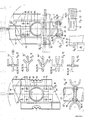
- plates 11 are arranged in pairs at regular intervals, so that there is a small distance between two plates.
- the sheets 11 are welded to the washing shaft 10 almost along a semicircle. Two such pairs of sheets are diametrically opposed to each other at the same height as the washing shaft 10.
- the plate pairs 11 adjacent in the longitudinal direction of the washing shaft 10 are arranged offset by 90 °. An arrangement offset by more than 90 ° or less than 90 ° is also possible.
- the sheets 11 have a projection 12 on their lower edge pointing away from the washing shaft 10, which together with the sheet 11 forms a slot 13.
- a U-profile rail 14 is inserted with its lower end piece, which abuts the metal sheets 11 with its rear side, a welded-on nose 15 protruding between the metal sheet pair 11 and being fixed there by means of a pin 16.
- the U-profile rail 14 is thus tilt and twist-proof on the pair of sheets attached.
- Sheet metal strips 17 made of a wear-resistant material are screwed onto the outside of the legs of the U-shaped rail 14.
- the free edges of these sheet metal strips 17 pointing away from the washing shaft 10 have a tooth profile 18 which effectively supports the division of the lumps of clay and sand.
- a transport arm 19 can be arranged between two diametrically opposed U-shaped rails 14, which consists of a transport plate 20 which runs at an angle to the longitudinal axis of the washing shaft 10.
- the transport plate 20 has on its edge facing the washing shaft 10 approximately in the middle a pin 21 which is inserted between the pair of plates 11 and fixed there.
- a free edge strip 22 of the transport plate 20 is angled so that it can be fastened to one of the legs of the U-shaped rail 14 or to the wear-resistant metal strip 17 arranged there.
- Each U-profile rail 14 lies with a considerable part of its length on two diametrically opposed pairs of sheets 11, so that the bending moment acting on the profile rail is small during operation of the washing system. If you want to replace the swords 14, it is sufficient to knock out the pin 16 and pull the rail out of the slot 13. This can even happen when the washing trough is full. Even the transport arms 19 can be quickly and easily removed or replaced at any time, depending on the speed at which the items to be washed are to receive in the washing trough.
- the design and attachment of the swords and transport arms according to the invention can also be used without problems with a washing shaft 10 with a square cross section.
- the swords 14 each lie on a square surface of the shaft 10.
- the transport arm 19 rests in the case of the action of bending forces with its free end piece after a short bending path on one leg of the U-profile rail 14. This prevents the transport arm 19 from breaking off.
- Fig. 3 shows in detail how the U-profile rail 14 is inserted with one end into the slot 13 provided on the pair of sheets 11.
- the U-back of the profile rail 14 comes to rest in the slot 13, while the projection 12, which divides the slot 13 together with each sheet 11, engages like a claw in the U-opening of the U-profile rail 14.
- the swords 14 and head parts 23 have a matching round profile which is open on one side and is provided with teeth 31 on the outer edge.
- the head part 23 abuts the face of the associated sword 14 in an aligned arrangement.
- the swords 14 have two on their profile back attached tabs 29, which have a rectangular plan and come to lie at some distance from the outer edge 30 of the sheets 11 between them.
- the tabs 29 are screwed to the metal sheets 11 at 32.
- the head part 23 is provided with a tab 25 which projects outside the tabs 29 of the swords 14 between the sheets 11 and occupies their full width.
- the tab 25 comes to rest on the tabs 29 of a pair of opposing swords 14 and is screwed to the sheets 11 at 26.
- FIG. 6 and 7 illustrate the additional attachment of transport plates 20 to the mounting points used to fasten the swords 14 and headboards 23.
- the transport plates 20 are placed on the outside of the plates 11 and screwed through with bolts 26, 32 which pass through the plates 11 and tabs 25, 29 of the swords 14 and head parts 23.
- Each transport arm 22 consists of an angle plate 33 and a wear plate 34 welded thereon, which extends at a short distance over the back of the adjacent pair of swords 14, which are arranged at 90 °.
- the additional transport plates 20 are used to adapt the conveying capacity of the washing shaft to the respective needs.
- FIGS. 9 to 12 show possible profiles for the sword 14 and the head part 23.
- FIG. 8 shows the U-profile already described with or without a central web 55
- FIG. 9 shows a 90 ° angle profile with or without central web 55
- FIG. 10 a trapezoidal profile with or without central web 55
- FIG. 11 a fork profile with a double web in the middle
- FIG. 12 a T-profile or flat iron profile.
- the profiles with center bar 55 are fork profiles with straight or sloping tines.
- a tab 25 is indicated, which extends between the sheets 11 of a pair of sheets, while the profile back is supported flush on the outer edges of the sheets 11.
- FIG. 8 shows the U-profile already described with or without a central web 55
- FIG. 9 shows a 90 ° angle profile with or without central web 55
- FIG. 10 a trapezoidal profile with or without central web 55
- FIG. 11 a fork profile with a double web in the middle
- FIG. 12 a T-profile or flat
- a double arrangement of such tabs 25 is indicated as an example, which overlaps a single sheet 11 welded to the washing shaft 10 in the form of a claw.
- profiles are suitable for the swords 14 and head parts 23 of the washing system according to the invention, which have a profile opening at the front in the direction of rotation of the washing shaft, which can be filled with clay, clay and other components of the items to be washed off.
- the T-profile of FIG. 12 is to be seen as the limit of such a profile.
- swords 14 can be combined with head parts 23 with the same profile, but also with different profiles, in order to adapt them to the respective laundry. If there is a high proportion of sand in the laundry, large profile openings are recommended. In the case of high amounts of clay and clay, it may also be advisable to attach the headboards to the swords with the opposite orientation, so that their profile openings face the swords. The headboards move then plow through the laundry to effectively dissolve it.
- FIG. 13 shows a U-profile suitable for swords 14 and head parts 23, the U-back of which is provided with bores 27 and slots 28 through which fine-grained components of the items to be washed can pass.
- a corresponding sieve-like design is also possible for the other profiles.
- pairs of sheets 11 are welded onto the washing shaft 10, which have an equilateral triangular outline and extend axially aligned in transverse planes.
- Plate-shaped comminution tools 35 are held on the sheets 11.
- Each plate 35 extends in the axial direction of the washing shaft 10 over three pairs of sheets 11, is supported with its back on its outer edge and has three tabs 36 which protrude between a pair of sheets 11 each.
- 11 head parts 24 are held on the pairs of sheets, which have a U-profile lying radially outside of the plates 35.
- the head parts 23 are each provided with a pair of tabs 37, which come to rest on the outside of the sheets 11 and are screwed together with the tab 36 of the plate body 35 at 38 to the sheets 11.
- Transport plates 20 are also fastened in the same place.
- the brackets of the head parts 23 each have a nose 39 which is supported on the outside of an adjacent plate body 35, so that there is an extremely stable construction that is closed over the circumference gives.
- the plate-shaped comminution tools 35 can be structured on the outside, so that retention chambers are formed for laundry to be fixed therein.
- 90 ° angles 40 are welded onto the plate 35.
- 17 shows the same for parallel webs, and FIG. 19 for webs 41 arranged transversely to one another.
- semicircular profiles 42 are welded onto the plate 35.
- 20 and 21 show a further embodiment variant, in which six scoop-shaped shredding tools 43 are arranged in a regular hexagon around the washing shaft 10.
- metal sheets 11 are welded onto the washing shaft 10 in pairs and lie in transverse planes and have a regular hexagonal layout.
- the sheets 11 are arranged in axial alignment.
- the blades 43 are supported with their backs on one of the outer edges of the pair of sheets 11, while a tab 44 welded onto the back projects between the sheets 11 and is screwed to it at 45.
- a front, radially outwardly projecting bottom portion 46 of the blade 43 is angled from the back of the blade and encloses a wedge angle with the wall of the trough.
- a nose 48 is welded onto the blade back, which engages in the opening of the respectively adjacent blade 43 and rests on the inside of the blade back. So it results Circumferential, extremely stable blade ring.
- the blades 43 are delimited to the side by triangular side walls 47.
- Hexagonal sheets 11 on the washing shaft 10 open up a variety of mounting options for shredding and transport tools, which are illustrated by way of example with reference to FIGS. 22 and 23.
- two swords 14 which have a serrated 18 U-profile, mounted on the sheets 11 in a diametrically opposite arrangement.
- the swords 14 rest with their backs on the outer edge of a pair of sheets 11.
- a tab 49 welded onto the back and projecting between the sheets 11 is screwed to it at 50.
- a holding plate 51 is mounted on an edge adjacent in the circumferential direction, which supports the back of the sword 14 and is used to attach a transport plate 20.
- the inner end of the holding plate 51 comes to lie between the plates 11 with which it is screwed at 52.
- a transport plate 20 is carried by a pair of axially offset holding plates 51.
- the transport plates 20 lie diametrically opposite one another in pairs on the circumference of the washing shaft 10. Similar to the transport plates 20, head parts 23 arranged upstream of the swords 14 can also be mounted on the hexagonal plates 11 (not shown).
- a modular system is thus provided which enables a washing shaft 10 to be equipped with comminution, washing and transport tools which are optimally matched to the composition of the respective items to be washed.
- the latter can also be cast elements instead of welded parts.
Landscapes
- Accessory Of Washing/Drying Machine, Commercial Washing/Drying Machine, Other Washing/Drying Machine (AREA)
- Disintegrating Or Milling (AREA)
- Separation Of Solids By Using Liquids Or Pneumatic Power (AREA)
- Cleaning By Liquid Or Steam (AREA)
- Mechanical Treatment Of Semiconductor (AREA)
Applications Claiming Priority (2)
| Application Number | Priority Date | Filing Date | Title |
|---|---|---|---|
| DE8809141U DE8809141U1 (de) | 1988-07-16 | 1988-07-16 | Waschanlage |
| DE8809141U | 1988-07-16 |
Publications (4)
| Publication Number | Publication Date |
|---|---|
| EP0351607A2 true EP0351607A2 (fr) | 1990-01-24 |
| EP0351607A3 EP0351607A3 (fr) | 1991-07-24 |
| EP0351607B1 EP0351607B1 (fr) | 1996-01-31 |
| EP0351607B2 EP0351607B2 (fr) | 1998-12-23 |
Family
ID=6826039
Family Applications (1)
| Application Number | Title | Priority Date | Filing Date |
|---|---|---|---|
| EP89111941A Expired - Lifetime EP0351607B2 (fr) | 1988-07-16 | 1989-06-30 | Dispositif de lavage |
Country Status (4)
| Country | Link |
|---|---|
| EP (1) | EP0351607B2 (fr) |
| AT (1) | ATE133585T1 (fr) |
| DE (2) | DE8809141U1 (fr) |
| ES (1) | ES2083962T5 (fr) |
Cited By (2)
| Publication number | Priority date | Publication date | Assignee | Title |
|---|---|---|---|---|
| AT398914B (de) * | 1993-03-25 | 1995-02-27 | Zwittnig Leopold | Verfahren zur behandlung von eisenbahn- oberbau- ausbaumaterial und vorrichtung zur durchführung des verfahrens |
| EP0712665A1 (fr) | 1994-11-15 | 1996-05-22 | Müller & Co. Aufbereitungstechnik Ag | Dispositif de lavage |
Family Cites Families (9)
| Publication number | Priority date | Publication date | Assignee | Title |
|---|---|---|---|---|
| DE1166111B (de) * | 1964-03-26 | Robert Pruess | Kiesreinigungsverfahren und Vorrichtung zur Durchfuehrung des Verfahrens | |
| GB191107786A (en) * | 1911-03-29 | 1911-10-12 | Joseph Southall | Improvements in Machines for Washing Sand. |
| US1786399A (en) * | 1930-04-19 | 1930-12-23 | Mclanahanstone Machine Company | Paddle ore-washing machine |
| GB477776A (en) * | 1936-07-03 | 1938-01-03 | Carolus Maria Joseph Antonius | Improved process and apparatus for breaking up mineral-containing clay, loam or the like masses by washing |
| CH210796A (de) * | 1939-07-06 | 1940-08-15 | Otto Dr Schneider | Rührvorrichtung für Waschmaschinen, insbesondere für Mineralien, wie Kies, Sand, Erze und dergl. |
| GB945247A (en) * | 1960-07-27 | 1963-12-23 | Parker Ltd Frederick | Sand and gravel washing machines |
| DE2454443C3 (de) * | 1974-11-16 | 1979-06-13 | Uhde Gmbh, 4600 Dortmund | Fermentative Umsetzung eines Nährstoffgemisches mittels Mikroorganismen |
| GB2081117B (en) * | 1980-07-29 | 1983-10-26 | Howard Machinery Ltd | Mixing and dispensing machine |
| DE3543181C2 (de) * | 1985-12-06 | 1995-03-30 | Cornelius Wilhelm | Waschanlage und Verfahren zum Waschen von Waschgut unter Verwendung der Waschanlage |
-
1988
- 1988-07-16 DE DE8809141U patent/DE8809141U1/de not_active Expired
-
1989
- 1989-06-30 DE DE58909585T patent/DE58909585D1/de not_active Expired - Fee Related
- 1989-06-30 EP EP89111941A patent/EP0351607B2/fr not_active Expired - Lifetime
- 1989-06-30 AT AT89111941T patent/ATE133585T1/de not_active IP Right Cessation
- 1989-06-30 ES ES89111941T patent/ES2083962T5/es not_active Expired - Lifetime
Cited By (2)
| Publication number | Priority date | Publication date | Assignee | Title |
|---|---|---|---|---|
| AT398914B (de) * | 1993-03-25 | 1995-02-27 | Zwittnig Leopold | Verfahren zur behandlung von eisenbahn- oberbau- ausbaumaterial und vorrichtung zur durchführung des verfahrens |
| EP0712665A1 (fr) | 1994-11-15 | 1996-05-22 | Müller & Co. Aufbereitungstechnik Ag | Dispositif de lavage |
Also Published As
| Publication number | Publication date |
|---|---|
| DE8809141U1 (de) | 1988-09-29 |
| ES2083962T5 (es) | 1999-03-01 |
| EP0351607B1 (fr) | 1996-01-31 |
| ATE133585T1 (de) | 1996-02-15 |
| ES2083962T3 (es) | 1996-05-01 |
| EP0351607A3 (fr) | 1991-07-24 |
| EP0351607B2 (fr) | 1998-12-23 |
| DE58909585D1 (de) | 1996-03-14 |
Similar Documents
| Publication | Publication Date | Title |
|---|---|---|
| EP0581770B1 (fr) | Rateau cribleur | |
| EP2870084B1 (fr) | Élévateur à godets présentant une courroie protégée par ligne de godets | |
| DE2648937B2 (de) | Kratzvorrichtung zum Reinigen eines endlosen Förderbandes | |
| DE2519646A1 (de) | Auskleidung fuer betonmischer, muehlentrommeln, abstuerzrinnen o.dgl. | |
| DE2801827A1 (de) | Vorrichtung an zerkleinerungsmaschinen, z.b. haeckslern | |
| EP0351607B1 (fr) | Dispositif de lavage | |
| EP0224920A2 (fr) | Installation de lavage et procédé de lavage de matières avec ladite installation | |
| DE19703495A1 (de) | Trogmischer, insbesondere Doppelwellen-Trogmischer | |
| DE2931578C2 (de) | Putzmaschine für Gußstücke | |
| DE202021002121U1 (de) | Zinkenbefestigung an einer Aufnahmeeinrichtung | |
| EP0270702A1 (fr) | Raclette pour transporteur à raclettes, en particulier pour exploitations minières souterraines | |
| DE2339058A1 (de) | Rost fuer eine muehle oder eine andere verarbeitungsanlage | |
| DE9408205U1 (de) | Anhänger zum Mischen, Zerkleinern und Verteilen von Tierfutter | |
| DE2149395A1 (de) | Vorrichtung zum uebergeben von mineralischem foerdergut aus einer ersten auf eine zweite foerdereinrichtung | |
| DE10329952B4 (de) | Seiherstab mit Distanzelement sowie Vorrichtung zum Abpressen | |
| DE3144613A1 (de) | Siebfoerderrost mit rotierenden rostwalzen | |
| EP3847116B1 (fr) | Dispositif d'enlèvement permettant d'enlever et d'évacuer un produit en vrac à partir d'une halde de produit en vrac à l'aide des éléments d'activation en forme de rabot | |
| WO2009132367A1 (fr) | Râteau de dégrillage destiné à une système circulant de dégrillage à râteau | |
| DE2345015C3 (de) | Kehrichtabfuhrwagen mit einem mit Förderschaufeln versehenen Förderrad | |
| DE3341830A1 (de) | Mischerschaufel fuer betonmischmaschinen | |
| DE3402986A1 (de) | Spaenefoerderer | |
| DE102024107540A1 (de) | Abstreifelement und Gurtabstreifer, insbesondere Untergurtabstreifer, mit einem solchen Abstreifelement zum Reinigen von Förderbändern | |
| DE1278408B (de) | Mischer fuer zum Anbacken neigendem Gut, insbesondere Asphalt | |
| AT220543B (fr) | ||
| DE29502697U1 (de) | Fördereinrichtung mit Förderschnecke |
Legal Events
| Date | Code | Title | Description |
|---|---|---|---|
| PUAI | Public reference made under article 153(3) epc to a published international application that has entered the european phase |
Free format text: ORIGINAL CODE: 0009012 |
|
| AK | Designated contracting states |
Kind code of ref document: A2 Designated state(s): AT BE CH DE ES FR GB GR IT LI LU NL SE |
|
| RBV | Designated contracting states (corrected) |
Designated state(s): AT BE CH DE ES FR GB IT LI NL SE |
|
| PUAL | Search report despatched |
Free format text: ORIGINAL CODE: 0009013 |
|
| AK | Designated contracting states |
Kind code of ref document: A3 Designated state(s): AT BE CH DE ES FR GB GR IT LI LU NL SE |
|
| 17P | Request for examination filed |
Effective date: 19920115 |
|
| 17Q | First examination report despatched |
Effective date: 19930621 |
|
| GRAA | (expected) grant |
Free format text: ORIGINAL CODE: 0009210 |
|
| AK | Designated contracting states |
Kind code of ref document: B1 Designated state(s): AT BE CH DE ES FR GB IT LI NL SE |
|
| REF | Corresponds to: |
Ref document number: 133585 Country of ref document: AT Date of ref document: 19960215 Kind code of ref document: T |
|
| REF | Corresponds to: |
Ref document number: 58909585 Country of ref document: DE Date of ref document: 19960314 |
|
| ITF | It: translation for a ep patent filed | ||
| REG | Reference to a national code |
Ref country code: CH Ref legal event code: NV Representative=s name: PATENTANWALTSBUERO JEAN HUNZIKER |
|
| REG | Reference to a national code |
Ref country code: ES Ref legal event code: FG2A Ref document number: 2083962 Country of ref document: ES Kind code of ref document: T3 |
|
| ET | Fr: translation filed | ||
| GBT | Gb: translation of ep patent filed (gb section 77(6)(a)/1977) |
Effective date: 19960503 |
|
| PLBI | Opposition filed |
Free format text: ORIGINAL CODE: 0009260 |
|
| PLBQ | Unpublished change to opponent data |
Free format text: ORIGINAL CODE: EPIDOS OPPO |
|
| PLBF | Reply of patent proprietor to notice(s) of opposition |
Free format text: ORIGINAL CODE: EPIDOS OBSO |
|
| 26 | Opposition filed |
Opponent name: NEUE AGIR AG Effective date: 19961028 |
|
| NLR1 | Nl: opposition has been filed with the epo |
Opponent name: NEUE AGIR AG |
|
| PLBF | Reply of patent proprietor to notice(s) of opposition |
Free format text: ORIGINAL CODE: EPIDOS OBSO |
|
| PLAW | Interlocutory decision in opposition |
Free format text: ORIGINAL CODE: EPIDOS IDOP |
|
| PLAW | Interlocutory decision in opposition |
Free format text: ORIGINAL CODE: EPIDOS IDOP |
|
| PUAH | Patent maintained in amended form |
Free format text: ORIGINAL CODE: 0009272 |
|
| STAA | Information on the status of an ep patent application or granted ep patent |
Free format text: STATUS: PATENT MAINTAINED AS AMENDED |
|
| 27A | Patent maintained in amended form |
Effective date: 19981223 |
|
| AK | Designated contracting states |
Kind code of ref document: B2 Designated state(s): AT BE CH DE ES FR GB IT LI NL SE |
|
| REG | Reference to a national code |
Ref country code: CH Ref legal event code: AEN Free format text: AUFRECHTERHALTUNG DES PATENTES IN GEAENDERTER FORM |
|
| GBTA | Gb: translation of amended ep patent filed (gb section 77(6)(b)/1977) |
Effective date: 19981223 |
|
| NLR2 | Nl: decision of opposition | ||
| NLR3 | Nl: receipt of modified translations in the netherlands language after an opposition procedure | ||
| REG | Reference to a national code |
Ref country code: ES Ref legal event code: DC2A Kind code of ref document: T5 Effective date: 19990119 |
|
| ITF | It: translation for a ep patent filed | ||
| ET3 | Fr: translation filed ** decision concerning opposition | ||
| REG | Reference to a national code |
Ref country code: GB Ref legal event code: IF02 |
|
| PGFP | Annual fee paid to national office [announced via postgrant information from national office to epo] |
Ref country code: GB Payment date: 20020412 Year of fee payment: 14 |
|
| PGFP | Annual fee paid to national office [announced via postgrant information from national office to epo] |
Ref country code: ES Payment date: 20020416 Year of fee payment: 14 |
|
| PGFP | Annual fee paid to national office [announced via postgrant information from national office to epo] |
Ref country code: BE Payment date: 20020424 Year of fee payment: 14 |
|
| PGFP | Annual fee paid to national office [announced via postgrant information from national office to epo] |
Ref country code: SE Payment date: 20020426 Year of fee payment: 14 |
|
| PG25 | Lapsed in a contracting state [announced via postgrant information from national office to epo] |
Ref country code: GB Free format text: LAPSE BECAUSE OF NON-PAYMENT OF DUE FEES Effective date: 20030630 Ref country code: BE Free format text: LAPSE BECAUSE OF NON-PAYMENT OF DUE FEES Effective date: 20030630 |
|
| PG25 | Lapsed in a contracting state [announced via postgrant information from national office to epo] |
Ref country code: SE Free format text: LAPSE BECAUSE OF NON-PAYMENT OF DUE FEES Effective date: 20030701 Ref country code: ES Free format text: LAPSE BECAUSE OF NON-PAYMENT OF DUE FEES Effective date: 20030701 |
|
| BERE | Be: lapsed |
Owner name: *MULLER & CO. AUFBEREITUNGSTECHNIK A.G. Effective date: 20030630 |
|
| GBPC | Gb: european patent ceased through non-payment of renewal fee |
Effective date: 20030630 |
|
| EUG | Se: european patent has lapsed | ||
| PGFP | Annual fee paid to national office [announced via postgrant information from national office to epo] |
Ref country code: FR Payment date: 20040427 Year of fee payment: 16 |
|
| PGFP | Annual fee paid to national office [announced via postgrant information from national office to epo] |
Ref country code: AT Payment date: 20040618 Year of fee payment: 16 |
|
| PGFP | Annual fee paid to national office [announced via postgrant information from national office to epo] |
Ref country code: NL Payment date: 20040628 Year of fee payment: 16 |
|
| REG | Reference to a national code |
Ref country code: ES Ref legal event code: FD2A Effective date: 20030701 |
|
| PGFP | Annual fee paid to national office [announced via postgrant information from national office to epo] |
Ref country code: DE Payment date: 20050420 Year of fee payment: 17 |
|
| PGFP | Annual fee paid to national office [announced via postgrant information from national office to epo] |
Ref country code: CH Payment date: 20050628 Year of fee payment: 17 |
|
| PG25 | Lapsed in a contracting state [announced via postgrant information from national office to epo] |
Ref country code: IT Free format text: LAPSE BECAUSE OF NON-PAYMENT OF DUE FEES;WARNING: LAPSES OF ITALIAN PATENTS WITH EFFECTIVE DATE BEFORE 2007 MAY HAVE OCCURRED AT ANY TIME BEFORE 2007. THE CORRECT EFFECTIVE DATE MAY BE DIFFERENT FROM THE ONE RECORDED. Effective date: 20050630 Ref country code: AT Free format text: LAPSE BECAUSE OF NON-PAYMENT OF DUE FEES Effective date: 20050630 |
|
| PG25 | Lapsed in a contracting state [announced via postgrant information from national office to epo] |
Ref country code: NL Free format text: LAPSE BECAUSE OF NON-PAYMENT OF DUE FEES Effective date: 20060101 |
|
| PG25 | Lapsed in a contracting state [announced via postgrant information from national office to epo] |
Ref country code: FR Free format text: LAPSE BECAUSE OF NON-PAYMENT OF DUE FEES Effective date: 20060228 |
|
| NLV4 | Nl: lapsed or anulled due to non-payment of the annual fee |
Effective date: 20060101 |
|
| REG | Reference to a national code |
Ref country code: FR Ref legal event code: ST Effective date: 20060228 |
|
| PG25 | Lapsed in a contracting state [announced via postgrant information from national office to epo] |
Ref country code: LI Free format text: LAPSE BECAUSE OF NON-PAYMENT OF DUE FEES Effective date: 20060630 Ref country code: CH Free format text: LAPSE BECAUSE OF NON-PAYMENT OF DUE FEES Effective date: 20060630 |
|
| PG25 | Lapsed in a contracting state [announced via postgrant information from national office to epo] |
Ref country code: DE Free format text: LAPSE BECAUSE OF NON-PAYMENT OF DUE FEES Effective date: 20070103 |
|
| REG | Reference to a national code |
Ref country code: CH Ref legal event code: PL |