EP0351738A2 - Elément ressort annulaire en matière plastique renforcée de fibres - Google Patents
Elément ressort annulaire en matière plastique renforcée de fibres Download PDFInfo
- Publication number
- EP0351738A2 EP0351738A2 EP89112985A EP89112985A EP0351738A2 EP 0351738 A2 EP0351738 A2 EP 0351738A2 EP 89112985 A EP89112985 A EP 89112985A EP 89112985 A EP89112985 A EP 89112985A EP 0351738 A2 EP0351738 A2 EP 0351738A2
- Authority
- EP
- European Patent Office
- Prior art keywords
- spring body
- winding
- winding body
- body according
- layers
- Prior art date
- Legal status (The legal status is an assumption and is not a legal conclusion. Google has not performed a legal analysis and makes no representation as to the accuracy of the status listed.)
- Granted
Links
Images

Classifications
-
- F—MECHANICAL ENGINEERING; LIGHTING; HEATING; WEAPONS; BLASTING
- F16—ENGINEERING ELEMENTS AND UNITS; GENERAL MEASURES FOR PRODUCING AND MAINTAINING EFFECTIVE FUNCTIONING OF MACHINES OR INSTALLATIONS; THERMAL INSULATION IN GENERAL
- F16F—SPRINGS; SHOCK-ABSORBERS; MEANS FOR DAMPING VIBRATION
- F16F1/00—Springs
- F16F1/36—Springs made of rubber or other material having high internal friction, e.g. thermoplastic elastomers
- F16F1/366—Springs made of rubber or other material having high internal friction, e.g. thermoplastic elastomers made of fibre-reinforced plastics, i.e. characterised by their special construction from such materials
-
- F—MECHANICAL ENGINEERING; LIGHTING; HEATING; WEAPONS; BLASTING
- F16—ENGINEERING ELEMENTS AND UNITS; GENERAL MEASURES FOR PRODUCING AND MAINTAINING EFFECTIVE FUNCTIONING OF MACHINES OR INSTALLATIONS; THERMAL INSULATION IN GENERAL
- F16F—SPRINGS; SHOCK-ABSORBERS; MEANS FOR DAMPING VIBRATION
- F16F1/00—Springs
- F16F1/36—Springs made of rubber or other material having high internal friction, e.g. thermoplastic elastomers
- F16F1/42—Springs made of rubber or other material having high internal friction, e.g. thermoplastic elastomers characterised by the mode of stressing
- F16F1/422—Springs made of rubber or other material having high internal friction, e.g. thermoplastic elastomers characterised by the mode of stressing the stressing resulting in flexion of the spring
- F16F1/426—Radial flexion of ring-type springs
-
- F—MECHANICAL ENGINEERING; LIGHTING; HEATING; WEAPONS; BLASTING
- F16—ENGINEERING ELEMENTS AND UNITS; GENERAL MEASURES FOR PRODUCING AND MAINTAINING EFFECTIVE FUNCTIONING OF MACHINES OR INSTALLATIONS; THERMAL INSULATION IN GENERAL
- F16F—SPRINGS; SHOCK-ABSORBERS; MEANS FOR DAMPING VIBRATION
- F16F2236/00—Mode of stressing of basic spring or damper elements or devices incorporating such elements
- F16F2236/02—Mode of stressing of basic spring or damper elements or devices incorporating such elements the stressing resulting in flexion of the spring
- F16F2236/025—Mode of stressing of basic spring or damper elements or devices incorporating such elements the stressing resulting in flexion of the spring radial flexion of ring-type springs
-
- Y—GENERAL TAGGING OF NEW TECHNOLOGICAL DEVELOPMENTS; GENERAL TAGGING OF CROSS-SECTIONAL TECHNOLOGIES SPANNING OVER SEVERAL SECTIONS OF THE IPC; TECHNICAL SUBJECTS COVERED BY FORMER USPC CROSS-REFERENCE ART COLLECTIONS [XRACs] AND DIGESTS
- Y10—TECHNICAL SUBJECTS COVERED BY FORMER USPC
- Y10T—TECHNICAL SUBJECTS COVERED BY FORMER US CLASSIFICATION
- Y10T428/00—Stock material or miscellaneous articles
- Y10T428/24—Structurally defined web or sheet [e.g., overall dimension, etc.]
- Y10T428/24058—Structurally defined web or sheet [e.g., overall dimension, etc.] including grain, strips, or filamentary elements in respective layers or components in angular relation
- Y10T428/24074—Strand or strand-portions
- Y10T428/24091—Strand or strand-portions with additional layer[s]
-
- Y—GENERAL TAGGING OF NEW TECHNOLOGICAL DEVELOPMENTS; GENERAL TAGGING OF CROSS-SECTIONAL TECHNOLOGIES SPANNING OVER SEVERAL SECTIONS OF THE IPC; TECHNICAL SUBJECTS COVERED BY FORMER USPC CROSS-REFERENCE ART COLLECTIONS [XRACs] AND DIGESTS
- Y10—TECHNICAL SUBJECTS COVERED BY FORMER USPC
- Y10T—TECHNICAL SUBJECTS COVERED BY FORMER US CLASSIFICATION
- Y10T428/00—Stock material or miscellaneous articles
- Y10T428/24—Structurally defined web or sheet [e.g., overall dimension, etc.]
- Y10T428/24058—Structurally defined web or sheet [e.g., overall dimension, etc.] including grain, strips, or filamentary elements in respective layers or components in angular relation
- Y10T428/24124—Fibers
Definitions
- the invention relates to an annular spring body made of fiber composite materials for vibration-isolating mounting of drive units, in particular in motor vehicles, which has a winding body with correspondingly wound in several layers, soaked with synthetic resin and is clamped on two opposite sides.
- the engine and transmission in motor vehicles are usually supported by means of rubber-metal elements in order to dampen vibrations and in particular to minimize the transmission of noise.
- bearing elements have a number of system-related disadvantages.
- the static deflection increases with the loading time as a result of the rubber being set, which means that if the pressure stops intervene prematurely, the acoustic insulation effect deteriorates.
- the dynamic stiffness of the bearing increases with increasing frequency, which favors the transmission of high-frequency vibrations. If a very soft basic coordination of the bearing is chosen as a countermeasure, this again results in a high setting of the bearing.
- the nature generally used for engine mounting is rubbers only suitable for ambient temperatures up to approx. 120 ° C.
- a spring body made of fiber composite materials is already known from DE-PS 30 22 418, which has a frame-like shape.
- this spring body is constructed from winding bodies layered in the frame plane and corresponding intermediate layers, which results in a very high rigidity of this spring body, and which, moreover, can only be produced in dimensions which are not suitable for use in motor vehicles.
- the present invention is therefore based on the object of creating a spring body which does not settle under static load and whose dynamic stiffness does not increase significantly above the static stiffness with increasing frequencies and which thus ensures good acoustic insulation.
- the invention provides that the spring body has at least one winding body made of several concentric winding layers of fibers running in the circumferential direction of the winding body and transverse to the direction of loading and at least one layer of fibers running at an angle to the other layers, and that the clamps are formed by force introduction elements are made of metallic brackets braced with respect to the winding body via elastic rubber layers, which at least partially surround the winding body.
- Such a spring body can be made sufficiently small and with a relatively thin wall thickness, it having optimal spring properties without static setting and without dynamic hardening.
- the individual winding bodies lying one inside the other can have outer contours running parallel to one another and the same distance from one another all the way round.
- the intermediate layer can consist of rubber, which is vulcanized onto the winding body.
- the intermediate layer consists of wrapped rubber bands running at an angle to the circumferential direction or else of layered wrapped sliding films.
- the slide films are expediently made of PTFE.
- the individual winding bodies can be braced against one another before the rubber is vulcanized.
- the rubber layers of the clamping between the stirrups and the winding body are expediently vulcanized. They can also be glued in or just pinched.
- the brackets can be designed as closed rings which enclose the winding body and have a rectangular cross section and have lateral connection elements. However, it is also possible to produce the brackets from two U-shaped brackets braced against one another.
- a rubber cushion can be vulcanized onto the inside of at least one of the brackets as a pressure stop.
- the spring body can have tension stops which consist of elements which are flexible or loose in the pressure direction and which have a stop which limits the deflection path when subjected to tensile stress.
- tension stops consist of elements which are flexible or loose in the pressure direction and which have a stop which limits the deflection path when subjected to tensile stress.
- the winding body can be pre-tensioned by tightening the pull stops.
- a spring body from a single winding body 1 is shown, which has an approximately oval shape with two straight central parts and semi-circular side parts.
- any other closed geometric shape is possible, such as an ellipse or a circle.
- the winding body 1 consists of several layers of fibers, which are wound circumferentially mainly transversely to the direction of stress.
- the outer layer 2 is shown in partial section. However, some of the layers, preferably the middle layer 3 of the winding body 1, expediently consist of fabric with transverse fibers or of fibers that are wound at an angle that deviates from the outer layer 2.
- Glass fibers, but also carbon fibers or aramid are suitable as reinforcing fibers, while thermosets or also thermoplastics, e.g. Polyetheretherketone (PEEK) can be used.
- PEEK Polyetheretherketone
- these force introduction elements can consist of brackets in the form of two U-shaped tabs 6 and 7, which counter against lateral webs 8 and 9 are braced and enclose the winding body 1 on the long sides.
- Elastic intermediate layers 10 and 11 made of rubber are arranged between the tabs 6 and 7 and the winding body 1. These rubber layers 10 and 11 can be vulcanized between the tabs 6 and 7 and the winding body 1; but it is also possible to glue them in there or even to clamp them between them.
- a pull stop which is only shown schematically, can be provided, which can consist, for example, of a flexible wire rope 12 and is fixed to the webs 8 and 9 of the two force introduction elements in an abutment 13.
- a pull stop 12 is flexible in the direction of pressure, but prevents the spring ring from expanding too much in the direction of pull.
- other configurations of the train stop are also possible, which, however, should always be designed to be flexible or loose in the pressure direction and limit the path in the train direction.
- two concentric winding bodies 20 and 21 running parallel to one another are provided, which are connected to one another via an elastic intermediate layer 22 made of rubber, which extends over the entire circumference of the intermediate space.
- the two winding bodies 20 and 21 are produced in the same manner and the same structure as the winding body 1 according to FIG. 1 and then the corresponding rubber layer 22 is vulcanized between the two winding bodies 20 and 21.
- the winding bodies 20 and 21 can be used without force when vulcanizing the rubber, ie without pre-tensioning. But it is also for achieving certain Internal stresses possible to brace the two winding bodies 20 and 21 against one another before vulcanization, as a result of which a non-linear or S-shaped static spring characteristic can be achieved.
- connection to the engine or the bearing point in the vehicle is carried out in the same way as in the spring body according to FIG. 1 via the rubber layers 10 and the brackets 6 and 7 and the external screw bolts 15.
- connection elements are also conceivable.
- internal pressure stops are provided in the spring body shown, which can consist, for example, of rubber pads 23 vulcanized onto the internal brackets 7.
- rubber pads 23 vulcanized onto the internal brackets 7.
- two winding bodies are provided with an intermediate vulcanized rubber layer.
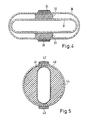
- FIG. 4 shows a further spring body with two winding bodies 30 and 31, which, however, only run parallel to one another over the straight sections.
- the entire gap between the two winding bodies 30 and 31 is also not filled with rubber, but rather only the two sections 32 and 33, which is fully sufficient for the coupling with the desired characteristics.
- the outer winding body 30 is provided with correspondingly vulcanized force introduction elements 34 and 35.
- a spring body with two winding bodies 40 and 41 of different geometric shape is shown.
- the cross section of the outer winding body 40 is circular, while the inner winding body 41 has an oval shape, the greatest length of which is slightly less than or equal to the inner diameter of the circular winding body 40.
- the inner winding body 41 is expediently designed to be much thinner than the outer one, so that when the force is introduced via the two, correspondingly curved force introduction elements 42 and 43, the inner winding body 41 can bulge outwards.
Landscapes
- Engineering & Computer Science (AREA)
- General Engineering & Computer Science (AREA)
- Mechanical Engineering (AREA)
- Health & Medical Sciences (AREA)
- Child & Adolescent Psychology (AREA)
- Springs (AREA)
- Vibration Prevention Devices (AREA)
Priority Applications (1)
| Application Number | Priority Date | Filing Date | Title |
|---|---|---|---|
| AT89112985T ATE90778T1 (de) | 1988-07-22 | 1989-07-14 | Ringfoermiger federkoerper aus faserverbundwerkstoffen. |
Applications Claiming Priority (4)
| Application Number | Priority Date | Filing Date | Title |
|---|---|---|---|
| DE3825022 | 1988-07-22 | ||
| DE3825022 | 1988-07-22 | ||
| DE3908474 | 1989-03-15 | ||
| DE3908474A DE3908474A1 (de) | 1988-07-22 | 1989-03-15 | Ringfoermiger federkoerper aus faserverbundwerkstoffen |
Publications (3)
| Publication Number | Publication Date |
|---|---|
| EP0351738A2 true EP0351738A2 (fr) | 1990-01-24 |
| EP0351738A3 EP0351738A3 (en) | 1990-11-07 |
| EP0351738B1 EP0351738B1 (fr) | 1993-06-16 |
Family
ID=25870400
Family Applications (1)
| Application Number | Title | Priority Date | Filing Date |
|---|---|---|---|
| EP89112985A Expired - Lifetime EP0351738B1 (fr) | 1988-07-22 | 1989-07-14 | Elément ressort annulaire en matière plastique renforcée de fibres |
Country Status (4)
| Country | Link |
|---|---|
| US (1) | US4942075A (fr) |
| EP (1) | EP0351738B1 (fr) |
| JP (1) | JP2566211B2 (fr) |
| DE (2) | DE3908474A1 (fr) |
Cited By (11)
| Publication number | Priority date | Publication date | Assignee | Title |
|---|---|---|---|---|
| EP0439685A1 (fr) * | 1989-11-18 | 1991-08-07 | Metzeler Gimetall Ag | Support en forme de manchon |
| EP0502458A3 (en) * | 1991-03-04 | 1992-10-28 | Metzeler Gimetall Ag | Damping support |
| EP0520875A1 (fr) * | 1991-06-27 | 1992-12-30 | Hutchinson S.A. | Dispositif élastique composite pour suspension d'installation vibrante |
| FR2689196A1 (fr) * | 1992-03-31 | 1993-10-01 | Hutchinson | Dispositif de filtrage des vibrations et système de fixation d'une charge sur un support comportant une pluralité de tels dispositifs. |
| DE19854692A1 (de) * | 1998-11-26 | 2000-06-15 | Eurocopter Deutschland | Federelement aus Faserverbundwerkstoff mit eingelagerten weichen Schichten |
| FR3024125A1 (fr) * | 2014-07-23 | 2016-01-29 | Airbus Operations Sas | Moyen ameliore de transmission d'efforts, agence entre un moteur d'aeronef et son mat d'accrochage |
| WO2015124693A3 (fr) * | 2014-02-24 | 2016-02-04 | ThyssenKrupp Federn und Stabilisatoren GmbH | Unité ressort de suspension pour un train de roulement de véhicule |
| EP3135463A3 (fr) * | 2015-08-24 | 2017-06-14 | EFFBE GmbH | Procede de fabrication d'un element de support et element de support |
| WO2019148231A1 (fr) * | 2018-02-05 | 2019-08-08 | Euler Rolle Thomas | Amortisseur de vibrations |
| CN113719568A (zh) * | 2021-08-23 | 2021-11-30 | 东莞市恒发电子科技有限公司 | 一种应用双u型钣金的xyz三向减振结构 |
| EP4293248A1 (fr) * | 2022-06-17 | 2023-12-20 | Hutchinson | Support antivibratoire et vehicule comportant un tel support antivibratoire |
Families Citing this family (41)
| Publication number | Priority date | Publication date | Assignee | Title |
|---|---|---|---|---|
| DE3931219C1 (fr) * | 1989-09-19 | 1990-08-09 | Metzeler Gmbh, 8000 Muenchen, De | |
| DE4017637A1 (de) * | 1990-05-31 | 1991-12-05 | Metzeler Gimetall Ag | Ringfoermiger federkoerper aus faserverbundwerkstoffen |
| JP2691471B2 (ja) * | 1990-08-22 | 1997-12-17 | 株式会社ブリヂストン | 免震支持装置 |
| FR2677724B1 (fr) * | 1991-06-11 | 1993-10-08 | Hutchinson | Perfectionnements aux anneaux limiteurs des supports elastiques et a leurs procedes de fabrication. |
| US5169110A (en) * | 1991-07-18 | 1992-12-08 | Aeroflex International Incorporated | Force-damping energy-removing isolator |
| JPH05183042A (ja) * | 1991-12-28 | 1993-07-23 | Disco Abrasive Syst Ltd | ウェーハの吸着方法 |
| US5275371A (en) * | 1992-01-22 | 1994-01-04 | Alcatel Network Systems, Inc. | Absorber tuning block retainer apparatus |
| FR2694792B1 (fr) * | 1992-08-14 | 1994-10-21 | Hutchinson | Biellette de reprise de couple pour moteur de véhicule. |
| US5664518A (en) * | 1994-01-14 | 1997-09-09 | Compsys, Inc. | Composite structures and method of making composite structures |
| US5800749A (en) * | 1994-01-14 | 1998-09-01 | Compsys, Inc. | Method of making composite structures |
| US6013213A (en) * | 1994-01-14 | 2000-01-11 | Compsys, Inc. | Method for making deformable composite structures and assembling composite article |
| US6004492A (en) * | 1994-01-14 | 1999-12-21 | Compsys, Inc. | Method of making composite spring and damper units |
| US5897818A (en) | 1994-01-14 | 1999-04-27 | Compsys, Inc. | Method for continuously manufacturing a composite preform |
| US5908591A (en) * | 1994-01-14 | 1999-06-01 | Compsys, Inc. | Method for making composite structures |
| US5549370A (en) * | 1994-11-07 | 1996-08-27 | Folsom; Mark F. | Fiber-reinforced plastic springs with helical fiber wind |
| FR2738888B1 (fr) * | 1995-09-20 | 1998-12-04 | Socitec | Dispositif antivibrations/antichocs du genre comportant un element porteur et un element porte unis par des segments de cable et des lames stabilisatrices |
| FR2758171B1 (fr) * | 1997-01-08 | 1999-03-19 | Max Sardou | Suspension composite |
| WO1998040643A1 (fr) * | 1997-03-11 | 1998-09-17 | Hutchinson T Gordon | Dispositif de type ressort |
| US6102379A (en) * | 1997-11-17 | 2000-08-15 | Hytec, Inc. | Torsion springs with visco-elastic damping |
| JPH11218185A (ja) * | 1998-02-03 | 1999-08-10 | Kurashiki Kako Co Ltd | 防振マウント |
| JP3072556B2 (ja) * | 1998-03-23 | 2000-07-31 | 日本ピラー工業株式会社 | フッ素樹脂系リング状摺動部材 |
| CA2239257A1 (fr) * | 1998-06-15 | 1999-12-15 | Yvon Lefebvre | Systeme de suspension et d'insonorisation |
| FR2794826B1 (fr) * | 1999-06-09 | 2001-09-14 | Hutchinson | Support antivibratoire equipe d'un cable limiteur inextensible |
| JP2001024051A (ja) | 1999-07-09 | 2001-01-26 | Tokyo Seimitsu Co Ltd | ウェーハ吸着パッド |
| FR2805870B1 (fr) * | 2000-03-06 | 2002-06-14 | Hutchinson | Dispositif elastique de suspension d'une structure vibrante a une structure rigide |
| US6803095B1 (en) | 2000-09-28 | 2004-10-12 | Lord Corporation | Composite shims having a laminate structure |
| DE10110604A1 (de) * | 2001-03-06 | 2002-10-02 | Continental Ag | Lager zur Lagerung einer schwingungsfähigen Masse |
| US7451966B1 (en) * | 2001-07-02 | 2008-11-18 | Knowles Gareth J | Isolator mount for shock and vibration |
| DE10141432A1 (de) * | 2001-08-23 | 2003-03-27 | Continental Ag | Blattfeder aus Faserverbundkunststoff |
| ES2233168B1 (es) * | 2003-02-21 | 2006-07-16 | Jose Gurri Molins | Elemento de absorcion y aislamiento de componentes bi-o-tri-dimensionales de movimiento , aplicable a maquinas, dispositivos e implementos mecanicos. |
| US20050044984A1 (en) * | 2003-08-27 | 2005-03-03 | Jones Brian H. | Reinforced tension and compression reacting strut and method of making same |
| GB0413276D0 (en) * | 2004-06-14 | 2004-07-14 | Rolls Royce Plc | Load reduced engine mount |
| FR2872784B1 (fr) * | 2004-07-09 | 2007-10-12 | Eurocopter France | Systeme de suspension d'un moteur d'aeronef a voilure tournante |
| DE102004050262A1 (de) * | 2004-10-14 | 2006-04-27 | Aweco Appliance Systems Gmbh & Co. Kg | Haushaltsmaschine mit einem Motor |
| US7249756B1 (en) * | 2006-02-01 | 2007-07-31 | Csa Engineering, Inc. | Low-profile, multi-axis, highly passively damped, vibration isolation mount |
| FR2949250B1 (fr) * | 2009-08-24 | 2012-01-06 | Aliaxis R & D Sas | Pont amortissant |
| US10570984B1 (en) * | 2017-06-28 | 2020-02-25 | United Launch Alliance, L.L.C. | Asymmetrically-shaped isolator |
| DE102019109554A1 (de) * | 2019-04-11 | 2020-10-15 | Danto Invention Gmbh & Co. Kg | Biegefederelement aus einem Faserkunststoffverbundmaterial |
| DE102019129581A1 (de) * | 2019-11-04 | 2021-05-06 | Danto Invention Gmbh & Co. Kg | Biegefederelement aus einem Faserkunststoffverbundmaterial |
| FI12778Y1 (fi) * | 2019-11-25 | 2020-09-30 | Labrys Oy | Jousielementti |
| US11831215B2 (en) * | 2021-05-06 | 2023-11-28 | Aac Microtech (Changzhou) Co., Ltd. | Linear vibration motor |
Family Cites Families (10)
| Publication number | Priority date | Publication date | Assignee | Title |
|---|---|---|---|---|
| DE1906805U (de) * | 1962-07-07 | 1964-12-17 | Emw Betr E Dipl Ing A Emmerlin | Zusammenvulkanisierter gummi-metallpuffer. |
| FR2138481A1 (en) * | 1971-05-26 | 1973-01-05 | Kleber Colombes | Reinforcement of rubber articles - by forming flexible hoops around article |
| US4196926A (en) * | 1978-02-27 | 1980-04-08 | The Budd Company | Energy attenuator and method of manufacturing thereof |
| JPS5533074U (fr) * | 1978-08-25 | 1980-03-03 | ||
| DE3022411A1 (de) * | 1980-06-14 | 1982-01-07 | Alfred Von 4178 Kevelaer Schuckmann | Behaelter zur einzel-portionierten ausgabe von tabletten |
| DE3022418C2 (de) * | 1980-06-14 | 1986-10-23 | Messerschmitt-Bölkow-Blohm GmbH, 8000 München | Rahmenförmiger Federkörper |
| JPS5945576B2 (ja) * | 1980-07-25 | 1984-11-07 | 株式会社日立製作所 | スライド機構による多数小片の同時移送方法 |
| JPS58124840A (ja) * | 1982-01-22 | 1983-07-25 | Toho Rayon Co Ltd | 重ね板ばね |
| US4653603A (en) * | 1983-08-25 | 1987-03-31 | Gordon Rosenmeier | Rotary fluid devices |
| JPS60125427A (ja) * | 1983-12-08 | 1985-07-04 | Nhk Spring Co Ltd | Frp板ばね |
-
1989
- 1989-03-15 DE DE3908474A patent/DE3908474A1/de active Granted
- 1989-07-14 DE DE8989112985T patent/DE58904696D1/de not_active Expired - Fee Related
- 1989-07-14 EP EP89112985A patent/EP0351738B1/fr not_active Expired - Lifetime
- 1989-07-19 JP JP1187211A patent/JP2566211B2/ja not_active Expired - Lifetime
- 1989-07-24 US US07/384,822 patent/US4942075A/en not_active Expired - Fee Related
Cited By (17)
| Publication number | Priority date | Publication date | Assignee | Title |
|---|---|---|---|---|
| EP0439685A1 (fr) * | 1989-11-18 | 1991-08-07 | Metzeler Gimetall Ag | Support en forme de manchon |
| EP0502458A3 (en) * | 1991-03-04 | 1992-10-28 | Metzeler Gimetall Ag | Damping support |
| EP0520875A1 (fr) * | 1991-06-27 | 1992-12-30 | Hutchinson S.A. | Dispositif élastique composite pour suspension d'installation vibrante |
| FR2678336A1 (fr) * | 1991-06-27 | 1992-12-31 | Hutchinson | Dispositif elastique composite pour suspension d'installation vibrante. |
| FR2689196A1 (fr) * | 1992-03-31 | 1993-10-01 | Hutchinson | Dispositif de filtrage des vibrations et système de fixation d'une charge sur un support comportant une pluralité de tels dispositifs. |
| EP0566436A1 (fr) * | 1992-03-31 | 1993-10-20 | Hutchinson | Dispositif de filtrage des vibrations et système de fixation d'une charge sur un support comportant une pluralité de tels dispositifs |
| US5358210A (en) * | 1992-03-31 | 1994-10-25 | Hutchinson | Device for filtering vibration, and a fixing system comprising a plurality of such devices for fixing a load on a support |
| DE19854692A1 (de) * | 1998-11-26 | 2000-06-15 | Eurocopter Deutschland | Federelement aus Faserverbundwerkstoff mit eingelagerten weichen Schichten |
| US10675935B2 (en) | 2014-02-24 | 2020-06-09 | ThyssenKrupp Federn und Stabilisatoren GmbH | Suspension spring unit for a vehicle chassis |
| WO2015124693A3 (fr) * | 2014-02-24 | 2016-02-04 | ThyssenKrupp Federn und Stabilisatoren GmbH | Unité ressort de suspension pour un train de roulement de véhicule |
| FR3024125A1 (fr) * | 2014-07-23 | 2016-01-29 | Airbus Operations Sas | Moyen ameliore de transmission d'efforts, agence entre un moteur d'aeronef et son mat d'accrochage |
| EP3135463A3 (fr) * | 2015-08-24 | 2017-06-14 | EFFBE GmbH | Procede de fabrication d'un element de support et element de support |
| WO2019148231A1 (fr) * | 2018-02-05 | 2019-08-08 | Euler Rolle Thomas | Amortisseur de vibrations |
| US11320015B2 (en) | 2018-02-05 | 2022-05-03 | Thomas Euler-Rolle | Vibration damper |
| CN113719568A (zh) * | 2021-08-23 | 2021-11-30 | 东莞市恒发电子科技有限公司 | 一种应用双u型钣金的xyz三向减振结构 |
| EP4293248A1 (fr) * | 2022-06-17 | 2023-12-20 | Hutchinson | Support antivibratoire et vehicule comportant un tel support antivibratoire |
| FR3136818A1 (fr) * | 2022-06-17 | 2023-12-22 | Hutchinson | Support antivibratoire et véhicule comportant un tel support antivibratoire. |
Also Published As
| Publication number | Publication date |
|---|---|
| JP2566211B2 (ja) | 1996-12-25 |
| EP0351738A3 (en) | 1990-11-07 |
| DE58904696D1 (de) | 1993-07-22 |
| US4942075A (en) | 1990-07-17 |
| DE3908474A1 (de) | 1990-01-25 |
| EP0351738B1 (fr) | 1993-06-16 |
| JPH0246331A (ja) | 1990-02-15 |
| DE3908474C2 (fr) | 1990-05-10 |
Similar Documents
| Publication | Publication Date | Title |
|---|---|---|
| EP0351738B1 (fr) | Elément ressort annulaire en matière plastique renforcée de fibres | |
| DE112004001430B4 (de) | Geräuscharmer Luftreifen | |
| EP0721410A1 (fr) | Element de structure composite utilise comme barre de liaison pour vehicules ferroviaires | |
| AT14651U1 (de) | Kältemittelverdichter | |
| EP2990684A1 (fr) | Élément à ressort de flexion constitué d'un matériau composite à base de fibres synthétiques | |
| DE4106838A1 (de) | Daempfendes aggregatlager | |
| EP2228564A1 (fr) | Roue dentée à compensation de jeu comprenant une roue dentée auxiliaire soutenue élastiquement sur une roue dentée principale transmettant le couple | |
| DE2656624A1 (de) | Befestigungsvorrichtung zur aufnahme von drucklasten | |
| EP0363563B1 (fr) | Support en caoutchouc | |
| EP0418717B1 (fr) | Elément ressort annulaire en matière composite renforcée par des fibres | |
| WO2010046191A1 (fr) | Palier hydraulique | |
| EP2570276A1 (fr) | Jambe de force et boîtier d'une jambe de force | |
| WO2019206588A1 (fr) | Élément ressort | |
| WO2006089637A1 (fr) | Bague d'isolation acoustique filetee pour points d'appui | |
| DE3313939A1 (de) | Elastisches lagerungselement zur schwingungsisolierenden und koerperschallisolierenden aufstellung von aggregaten | |
| DE69001875T2 (de) | Elastisches Lager, insbesondere für einen Fahrzeugmotor. | |
| EP0698747A1 (fr) | Accouplement élastique en rotation avec amortisseur de torsion intégré | |
| DE2543612A1 (de) | Riemenscheibe fuer veraenderliche drehzahl | |
| DE102020114264A1 (de) | Schwingungsentkoppeltes Wälzlager | |
| EP0459220B1 (fr) | Ressort de forme circulaire avec des matières composites renforcées par des fibres | |
| DE4336559A1 (de) | Schwingungsdämpfer | |
| DE102011017651A1 (de) | Drehschwingungsdämpfer, insbesondere für den Antriebsstrang eines Fahrzeugs | |
| DE69624190T2 (de) | Verbindungs- und Kraftübertragungsvorrichtung zwischen zwei koaxialen drehenden Teilen | |
| DE2603995A1 (de) | Verbindungsglied | |
| DE202014004620U1 (de) | Torsionstilger mit einstellbarer Dämpfung und Frequenz |
Legal Events
| Date | Code | Title | Description |
|---|---|---|---|
| PUAI | Public reference made under article 153(3) epc to a published international application that has entered the european phase |
Free format text: ORIGINAL CODE: 0009012 |
|
| 17P | Request for examination filed |
Effective date: 19890714 |
|
| AK | Designated contracting states |
Kind code of ref document: A2 Designated state(s): AT CH DE ES FR GB IT LI NL SE |
|
| PUAL | Search report despatched |
Free format text: ORIGINAL CODE: 0009013 |
|
| AK | Designated contracting states |
Kind code of ref document: A3 Designated state(s): AT CH DE ES FR GB IT LI NL SE |
|
| RAP1 | Party data changed (applicant data changed or rights of an application transferred) |
Owner name: METZELER GIMETALL AG |
|
| 17Q | First examination report despatched |
Effective date: 19920416 |
|
| GRAA | (expected) grant |
Free format text: ORIGINAL CODE: 0009210 |
|
| AK | Designated contracting states |
Kind code of ref document: B1 Designated state(s): AT CH DE ES FR GB IT LI NL SE |
|
| PG25 | Lapsed in a contracting state [announced via postgrant information from national office to epo] |
Ref country code: IT Free format text: LAPSE BECAUSE OF FAILURE TO SUBMIT A TRANSLATION OF THE DESCRIPTION OR TO PAY THE FEE WITHIN THE PRESCRIBED TIME-LIMIT;WARNING: LAPSES OF ITALIAN PATENTS WITH EFFECTIVE DATE BEFORE 2007 MAY HAVE OCCURRED AT ANY TIME BEFORE 2007. THE CORRECT EFFECTIVE DATE MAY BE DIFFERENT FROM THE ONE RECORDED. Effective date: 19930616 Ref country code: ES Free format text: THE PATENT HAS BEEN ANNULLED BY A DECISION OF A NATIONAL AUTHORITY Effective date: 19930616 Ref country code: NL Effective date: 19930616 |
|
| REF | Corresponds to: |
Ref document number: 90778 Country of ref document: AT Date of ref document: 19930715 Kind code of ref document: T |
|
| PG25 | Lapsed in a contracting state [announced via postgrant information from national office to epo] |
Ref country code: AT Effective date: 19930714 |
|
| REF | Corresponds to: |
Ref document number: 58904696 Country of ref document: DE Date of ref document: 19930722 |
|
| ET | Fr: translation filed | ||
| PG25 | Lapsed in a contracting state [announced via postgrant information from national office to epo] |
Ref country code: LI Effective date: 19930731 Ref country code: CH Effective date: 19930731 |
|
| GBT | Gb: translation of ep patent filed (gb section 77(6)(a)/1977) |
Effective date: 19930712 |
|
| NLV1 | Nl: lapsed or annulled due to failure to fulfill the requirements of art. 29p and 29m of the patents act | ||
| REG | Reference to a national code |
Ref country code: CH Ref legal event code: PL |
|
| PLBE | No opposition filed within time limit |
Free format text: ORIGINAL CODE: 0009261 |
|
| STAA | Information on the status of an ep patent application or granted ep patent |
Free format text: STATUS: NO OPPOSITION FILED WITHIN TIME LIMIT |
|
| 26N | No opposition filed | ||
| PGFP | Annual fee paid to national office [announced via postgrant information from national office to epo] |
Ref country code: SE Payment date: 19940731 Year of fee payment: 6 |
|
| EAL | Se: european patent in force in sweden |
Ref document number: 89112985.0 |
|
| PG25 | Lapsed in a contracting state [announced via postgrant information from national office to epo] |
Ref country code: SE Effective date: 19950715 |
|
| EUG | Se: european patent has lapsed |
Ref document number: 89112985.0 |
|
| PGFP | Annual fee paid to national office [announced via postgrant information from national office to epo] |
Ref country code: GB Payment date: 20000623 Year of fee payment: 12 |
|
| PGFP | Annual fee paid to national office [announced via postgrant information from national office to epo] |
Ref country code: FR Payment date: 20000718 Year of fee payment: 12 |
|
| PG25 | Lapsed in a contracting state [announced via postgrant information from national office to epo] |
Ref country code: GB Free format text: LAPSE BECAUSE OF NON-PAYMENT OF DUE FEES Effective date: 20010714 |
|
| GBPC | Gb: european patent ceased through non-payment of renewal fee |
Effective date: 20010714 |
|
| PG25 | Lapsed in a contracting state [announced via postgrant information from national office to epo] |
Ref country code: FR Free format text: LAPSE BECAUSE OF NON-PAYMENT OF DUE FEES Effective date: 20020329 |
|
| REG | Reference to a national code |
Ref country code: FR Ref legal event code: ST |
|
| PGFP | Annual fee paid to national office [announced via postgrant information from national office to epo] |
Ref country code: DE Payment date: 20060727 Year of fee payment: 18 |
|
| PG25 | Lapsed in a contracting state [announced via postgrant information from national office to epo] |
Ref country code: DE Free format text: LAPSE BECAUSE OF NON-PAYMENT OF DUE FEES Effective date: 20080201 |