EP0351877B1 - Dispositif de manoeuvre et de guidage d'une porte de véhicule, en particulier d'un autobus - Google Patents
Dispositif de manoeuvre et de guidage d'une porte de véhicule, en particulier d'un autobus Download PDFInfo
- Publication number
- EP0351877B1 EP0351877B1 EP19890113463 EP89113463A EP0351877B1 EP 0351877 B1 EP0351877 B1 EP 0351877B1 EP 19890113463 EP19890113463 EP 19890113463 EP 89113463 A EP89113463 A EP 89113463A EP 0351877 B1 EP0351877 B1 EP 0351877B1
- Authority
- EP
- European Patent Office
- Prior art keywords
- door
- guide
- support structure
- holes
- channel
- Prior art date
- Legal status (The legal status is an assumption and is not a legal conclusion. Google has not performed a legal analysis and makes no representation as to the accuracy of the status listed.)
- Expired - Lifetime
Links
Images

Classifications
-
- E—FIXED CONSTRUCTIONS
- E05—LOCKS; KEYS; WINDOW OR DOOR FITTINGS; SAFES
- E05F—DEVICES FOR MOVING WINGS INTO OPEN OR CLOSED POSITION; CHECKS FOR WINGS; WING FITTINGS NOT OTHERWISE PROVIDED FOR, CONCERNED WITH THE FUNCTIONING OF THE WING
- E05F15/00—Power-operated mechanisms for wings
- E05F15/50—Power-operated mechanisms for wings using fluid-pressure actuators
- E05F15/53—Power-operated mechanisms for wings using fluid-pressure actuators for swinging wings
-
- B—PERFORMING OPERATIONS; TRANSPORTING
- B60—VEHICLES IN GENERAL
- B60J—WINDOWS, WINDSCREENS, NON-FIXED ROOFS, DOORS, OR SIMILAR DEVICES FOR VEHICLES; REMOVABLE EXTERNAL PROTECTIVE COVERINGS SPECIALLY ADAPTED FOR VEHICLES
- B60J5/00—Doors
- B60J5/04—Doors arranged at the vehicle sides
- B60J5/06—Doors arranged at the vehicle sides slidable; foldable
- B60J5/062—Doors arranged at the vehicle sides slidable; foldable for utility vehicles or public transport
-
- B—PERFORMING OPERATIONS; TRANSPORTING
- B61—RAILWAYS
- B61D—BODY DETAILS OR KINDS OF RAILWAY VEHICLES
- B61D19/00—Door arrangements specially adapted for rail vehicles
- B61D19/02—Door arrangements specially adapted for rail vehicles for carriages
-
- E—FIXED CONSTRUCTIONS
- E05—LOCKS; KEYS; WINDOW OR DOOR FITTINGS; SAFES
- E05D—HINGES OR SUSPENSION DEVICES FOR DOORS, WINDOWS OR WINGS
- E05D15/00—Suspension arrangements for wings
- E05D15/28—Suspension arrangements for wings supported on arms movable in horizontal plane
- E05D15/30—Suspension arrangements for wings supported on arms movable in horizontal plane with pivoted arms and sliding guides
-
- E—FIXED CONSTRUCTIONS
- E05—LOCKS; KEYS; WINDOW OR DOOR FITTINGS; SAFES
- E05Y—INDEXING SCHEME ASSOCIATED WITH SUBCLASSES E05D AND E05F, RELATING TO CONSTRUCTION ELEMENTS, ELECTRIC CONTROL, POWER SUPPLY, POWER SIGNAL OR TRANSMISSION, USER INTERFACES, MOUNTING OR COUPLING, DETAILS, ACCESSORIES, AUXILIARY OPERATIONS NOT OTHERWISE PROVIDED FOR, APPLICATION THEREOF
- E05Y2900/00—Application of doors, windows, wings or fittings thereof
- E05Y2900/50—Application of doors, windows, wings or fittings thereof for vehicles
- E05Y2900/506—Application of doors, windows, wings or fittings thereof for vehicles for buses
-
- E—FIXED CONSTRUCTIONS
- E05—LOCKS; KEYS; WINDOW OR DOOR FITTINGS; SAFES
- E05Y—INDEXING SCHEME ASSOCIATED WITH SUBCLASSES E05D AND E05F, RELATING TO CONSTRUCTION ELEMENTS, ELECTRIC CONTROL, POWER SUPPLY, POWER SIGNAL OR TRANSMISSION, USER INTERFACES, MOUNTING OR COUPLING, DETAILS, ACCESSORIES, AUXILIARY OPERATIONS NOT OTHERWISE PROVIDED FOR, APPLICATION THEREOF
- E05Y2900/00—Application of doors, windows, wings or fittings thereof
- E05Y2900/50—Application of doors, windows, wings or fittings thereof for vehicles
- E05Y2900/51—Application of doors, windows, wings or fittings thereof for vehicles for railway cars or mass transit vehicles
Definitions
- This invention relates to a device for operating and guiding a vehicle door in accordance with the preamble of claim 1, particularly of a motor bus or other public passenger transport vehicle.
- each half door comprises a support leaf rigid with its hinge pivots and a suspended leaf hinged to the support leaf.
- the half doors are operated and guided by a device comprising a support base disposed above the door compartment, two cylinders connected to said support base and acting on respective levers rigid with the hinge pivots, and a longitudinal guide fixed lowerly to the support base and slidingly engaged by a pair of wheels rotatable on pins rigid with the respective driven leaves.
- the leaves are hinged in an approximately central position to respective arms rigid with the hinge pivots and are operated and guided by a substantially analogous device.
- a device for operating and guiding a vehicle door as set forth in the preamble of claim 1 is disclosed in DE-C-819 781.
- the object of the present invention is to provide a device for operating and guiding a vehicle door which can be used both for folding doors and for rotary-sliding doors.
- a device for operating and guiding a vehicle door of the type comprising a support structure to be mounted in the upper region of the door housing compartment provided in a body side of said vehicle, at least one pneumatic cylinder connected to said support structure and arranged to rotate a hinge pivot of a leaf of said door, guide means secured lowerly to said support structure and able to slidingly house a corresponding guide element of said door so as to guide it along a slide surface parallel to said body side, and means for fixing said guide means to said support structure, characterised in that said guide means comprise a section bar provided with a fixing portion and a guide portion defining a channel parallel to but asymmetric about the longitudinal plane of symmetry through said fixing means, a longitudinal middle surface of said channel defining said slide surface of said guide element of said door, said section bar being fixable to said support structure in two positions, of which one is rotated through 180°C from the other about a vertical axis and which define two different distances of said slide surface from the outer profile of
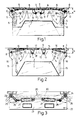
- the reference numeral 1 indicates overall a folding door for a motor bus.
- the door 1 comprises two half doors 2 housed in a door compartment 3 provided in a body side 4 of the motor bus.
- Said half doors 2 consist of respective support leaves 5, and driven leaves 6 hinged to the support leaves 5 and disposed so that when the door is closed they mate with respective side edges 7, conveniently provided with gaskets of soft material, not shown.
- the support leaves 5 are rigid with respective rotatable hinge pivots B disposed on the sides of the door compartment 3.
- the wheels 11 are constrained to slide horizontally along a surface 13 parallel to the body side 4.
- the distance of the surface 13 from the outer profile of the body side 4 is indicated by "a".
- the two half doors 2 are opened by rotating the hinge pivots 8 in the direction indicated by the arrows, using a control device described in detail hereinafter.
- the door is closed by rotating the hinge pivots 8 in the opposite direction.
- the distance "a” obviously influences the position assumed by the half doors 2 when closed and open. Specifically, the distance between the wheels 11 when in the closed position reduces as "a" reduces.
- FIG 2 shows a door 1' comprising two rotary-sliding half doors or leaves 15. Said door 1' is described hereinafter using the sail reference numerals to indicate parts equal or corresponding to parts already described with reference to Figure 1.
- the leaves are connected to respective hinge pivots 8 by respective bars 16 rigid at one end with the hinge pivots 8 and hinged at their other end to the upper central region of the leaves 15.
- the wheels 11 are constrained to slide along a surface 17 parallel to the body side 4.
- the distance of the surface 17 from the outer profile of the body side 4 is indicated by "b". Again in this case the leaves 15 are opened by rotating the hinge pivots 8.
- the distance "b" cannot be increased indefinitely at the design stage because it would result in an excessive distance between the wheels 11 when the door 1' is closed and thus involve the risk that a load applied to the leaves 15 at their edge 7 could cause them to rotate about the wheels 11 and thus accidentally open.
- Figure 3 diagrammatically illustrates a device for controlling the opening of the doors 1 or 1'.
- This device comprises substantially a pair of pneumatic cylinders 21 which are housed in a compartment 22 disposed above the door compartment 3 and are hinged to a support base 23 which separates said compartment from the door compartment 3.
- the support base 23 comprises two lateral through seats, not shown, through which the upper ends 24 of the hinge pivots 8 penetrate into the compartment 22.
- control device 20 comprises bivalent guide means, ie able to form both the surface 13 for the folding half doors and the surface 17 for the rotary-sliding half doors 15, by simply varying the mounting configuration.
- Said guide means comprise specifically a section bar 30 ( Figures 4 and 5) conveniently extruded of aluminium alloy, comprising a substantially flat fixing portion 31 provided with a plurality of through holes 29 and fixed to the support base 23 by a plurality of screws 32 which pass through said holes 29 and are screwed into respective seats 33 in the base 23, and a guide portion 34 of substantially rectangular trapezium cross-section with its minor base facing downwards.
- the holes 29 are disposed, symmetrically about a vertical longitudinal plane 36, in two parallel rows in correspondence with lateral regions of the fixing portion 31 which project from the guide portion 34.
- the seats 33 are disposed symmetrically about a vertical plane 36' parallel to the body side 4 of the motor bus and disposed at a distance from the body profile equal to the mean of the distances "a” and "b” as heretofore described.
- a channel 35 having a substantially rectangular cross-section which is asymmetric about the plane 36. Specifically, the distance between the vertical central plane 37 through the channel 35 and said plane 36, indicated in the figure by "c", is equal to one half the difference between the distances "a" and "b".
- the support base 23 conveniently has a box structure obtained by welding together two shaped plates 38, 39, the seats 32 comprising a respective through hole 40 in the lower plate 39 and a respective threaded nut 41 welded to the inside of the plate 39 in correspondence with said hole 40.
- the section bar 30 comprises respective seats housing two strips 44 of material with a low coefficient of friction, and between which the wheels 11 run.
- the wheels 11 are conveniently constructed of steel and mounted on their pins by way of rolling-contact bearings, not shown.
- the strips 44 are conveniently of a softer material, such as a plastics material.
- the device 20 can be used in combination with folding doors or doors with rotary-sliding leaves without any modification and without varying the vehicle assembly cycle, but simply by mounting one element (the section bar 30) in a rotated position and using for this purpose the same fixing means (screws 32 and seats 33) in the two versions.
Landscapes
- Engineering & Computer Science (AREA)
- Mechanical Engineering (AREA)
- Power-Operated Mechanisms For Wings (AREA)
- Support Devices For Sliding Doors (AREA)
- Lock And Its Accessories (AREA)
Claims (10)
- Un dispositif de manoeuvre et de guidage d'une porte de véhicule (1), du type comprenant une structure de support (23), à monter dans la partie supérieure du compartiment formant carter de logement de porte (22) monté sur un côté de la caisse dudit véhicule, au moins un cylindre pneumatique (21) relié à ladite structure de support (23) et agencé pour faire tourner le pivot d'articulation (8) d'un battant de ladite porte (1), des moyens de guidage fixés à la partie inférieure de ladite structure de support (23) et susceptibles d'abriter un élément de guidage correspondant (11), monté glissant, de ladite porte (1) de manière à le guider le long d'une surface de glissement parallèle audit côté de caisse, et des moyens (29, 32, 33) pour fixer lesdits moyens de guidage sur ladite structure de support (23), caractérisé en ce que lesdits moyens de guidage comprennent une barre profilée (30) comprenant une partie de fixation (31) et une partie de guidage (34) définissant un profilé en U (35), parallèle et asymétrique par rapport au plan longitudinal de symétrie (36, 36') traversant lesdits moyens de fixation (29, 32, 33), une surface médiane longitudinale (37) dudit profilé en U définissant ladite surface de glissement (13, 17) dudit élément de guidage (11) de ladite porte (1, 1'), ladite barre profilée (30) pouvant être fixée sur ladite structure de support (23) en deux positions, l'une d'elles pouvant effectuer une rotation de 180° par rapport à l'autre, autour s'un axe vertical et définissant deux distances différentes (a, b) de ladite surface de glissement (13, 17) par rapport au profil extérieur dudit côté de caisse (4) dudit véhicule.
- Un dispositif selon la revendication 1, caractérisé en ce que lesdits moyens de fixation comprennent une pluralité de trous (29) ménagés dans ladite partie de fixation (31), des sièges correspondants (33) étant prévus dans ladite structure de support (23), et des vis (32) traversant lesdits trous et vissées dans lesdits sièges (33).
- Un dispositif selon la revendication 1 ou 2, caractérisé en ce que ladite partie de fixation (31) est de forme sensiblement plate, ladite partie de guidage (34) ayant, en coupe transversale, sensiblement la forme d'un trapèze rectangle dont la petite base est tournée vers le bas, vis-à-vis de laquelle ledit profilé en U (35) est monté.
- Un dispositif selon l'une quelconque des précédentes revendications, caractérisé en ce qu'il comprend une paire de bandes plates (44) à faible coefficient de frottement, disposées à l'intérieur, sur les côtés dudit profité en U (35) et solidaires dudit élément de guidage (11) de la porte (1, 1').
- Un dispositif selon l'une quelconque des précédentes revendications, caractérisé en ce que lesdits trous (29) sont disposés en deux rangées parallèles le long des zones latérales respectives de ladite partie de fixation (31) disposées en saillie par rapport à ladite partie de guidage (34) de ladite barre profilée (30).
- Un dispositif selon l'une quelconque des précédentes revendications, caractérisé en ce que ladite structure de support comprend une face de support sensiblement plate (23) de la structure en caisson.
- Un dispositif selon la revendication 6, caractérisé en ce que lesdits sièges (33) comprennent une pluralité de trous traversants (40) ménagés dans la paroi inférieure (39) de ladite base de support (23) et une pluralité d'écrous taraudés correspondants (41), soudés à l'intérieur de ladite paroi (39), en correspondance avec lesdits trous (41).
- Un dispositif selon l'une quelconque des précédentes revendications, caractérisé en ce qu'il comprend deux cylindres (21) pour manoeuvrer les demi-portes respectives (2, 15) de ladite porte (1, 1').
- Un dispositif selon l'une quelconque des précédentes revendications, caractérisé en ce qu'il est appliqué à une porte pliante (1).
- Un dispositif selon l'une quelconque des précédentes revendications 1 à 8, caractérisé en ce qu'il est appliqué à une porte (1') comprenant des battants glissants rotatifs (15).
Applications Claiming Priority (2)
| Application Number | Priority Date | Filing Date | Title |
|---|---|---|---|
| IT5331588U | 1988-07-22 | ||
| IT5331588U IT215087Z2 (it) | 1988-07-22 | 1988-07-22 | Dispositivo per l azionamento e la guida di una porta di un veicolo particolarmente un autobus |
Publications (2)
| Publication Number | Publication Date |
|---|---|
| EP0351877A1 EP0351877A1 (fr) | 1990-01-24 |
| EP0351877B1 true EP0351877B1 (fr) | 1992-12-30 |
Family
ID=11281727
Family Applications (1)
| Application Number | Title | Priority Date | Filing Date |
|---|---|---|---|
| EP19890113463 Expired - Lifetime EP0351877B1 (fr) | 1988-07-22 | 1989-07-21 | Dispositif de manoeuvre et de guidage d'une porte de véhicule, en particulier d'un autobus |
Country Status (4)
| Country | Link |
|---|---|
| EP (1) | EP0351877B1 (fr) |
| DE (1) | DE68904130T2 (fr) |
| ES (1) | ES2037918T3 (fr) |
| IT (1) | IT215087Z2 (fr) |
Families Citing this family (2)
| Publication number | Priority date | Publication date | Assignee | Title |
|---|---|---|---|---|
| EP3569805A1 (fr) | 2018-05-18 | 2019-11-20 | Masats, S.A. | Système de fermeture et d'ouverture d'au moins un battant d'une porte pivotant vers l'intérieur |
| DE202022104049U1 (de) * | 2022-07-19 | 2023-10-20 | Bode - Die Tür Gmbh | Schwenktüranordnung mit Rollenbolzenschiene in oberer Portalleiste |
Family Cites Families (4)
| Publication number | Priority date | Publication date | Assignee | Title |
|---|---|---|---|---|
| DE819781C (de) * | 1949-07-26 | 1951-11-05 | Dowaldwerke | Schwingtuer, vornehmlich fuer Fahrzeuge |
| US3435877A (en) * | 1967-08-16 | 1969-04-01 | Francis B Horton | Folding and stacking door means |
| US4346931A (en) * | 1980-11-12 | 1982-08-31 | General Motors Corporation | Bifold vehicle door assembly |
| FR2577271B1 (fr) * | 1985-02-12 | 1991-04-05 | Renault Vehicules Ind | Porte a vantail pivotant guide |
-
1988
- 1988-07-22 IT IT5331588U patent/IT215087Z2/it active
-
1989
- 1989-07-21 DE DE1989604130 patent/DE68904130T2/de not_active Expired - Fee Related
- 1989-07-21 ES ES89113463T patent/ES2037918T3/es not_active Expired - Lifetime
- 1989-07-21 EP EP19890113463 patent/EP0351877B1/fr not_active Expired - Lifetime
Also Published As
| Publication number | Publication date |
|---|---|
| ES2037918T3 (es) | 1993-07-01 |
| IT215087Z2 (it) | 1990-07-30 |
| DE68904130T2 (de) | 1993-07-15 |
| IT8853315V0 (it) | 1988-07-22 |
| DE68904130D1 (de) | 1993-02-11 |
| EP0351877A1 (fr) | 1990-01-24 |
Similar Documents
| Publication | Publication Date | Title |
|---|---|---|
| EP0140245B1 (fr) | Mécanisme de charnière pour portière latérale de véhicule automobile | |
| US11541937B2 (en) | Closure module frame structure of vehicle | |
| GB2027098A (en) | Door assembly | |
| ITTO970478A1 (it) | Dispositivo di articolazione centrale per schienale a sezione separate di un sedile posteriore di un autoveicolo. | |
| EP0136714B1 (fr) | Méchanisme de charnière des portes latérales de véhicules automobiles | |
| PT92382B (pt) | Porta | |
| EP1281553B1 (fr) | Bâti pour la portière de la malle arrière d'un véhicule | |
| CA2226775A1 (fr) | Ensemble charniere pour porte a sections | |
| EP0351877A1 (fr) | Dispositif de manoeuvre et de guidage d'une porte de véhicule, en particulier d'un autobus | |
| US6286261B1 (en) | Vehicle sliding door track and guide elements | |
| GB2184778A (en) | Friction stay | |
| US10882385B2 (en) | Cover apparatus for truck cargo box | |
| KR20120092666A (ko) | 윈도우 또는 도어의 이동 가능한 윙을 위한 피팅 | |
| US5096238A (en) | Secondary door locking system | |
| US20020050026A1 (en) | Hinge for a motor vehicle rear door | |
| KR20010061859A (ko) | 체커 기능을 갖는 도어힌지 | |
| CN110552584A (zh) | 一种动力系统及轿厢 | |
| HU203801B (en) | Door fixing device for doors of motor vehicle | |
| NL8005964A (nl) | Instelbare veergrendel. | |
| EP0027481A1 (fr) | Mécanisme de charnière pour porte, et porte sectionnelle relevable et coulissante équipée d'une telle charnière | |
| US3022817A (en) | Three-way double garage door | |
| CN211008149U (zh) | 一种用于门扇的动力系统及轿厢 | |
| JPH04258479A (ja) | ヒンジとして役立つ二部品型機構 | |
| KR20020022414A (ko) | 자동차용 도어힌지 | |
| CN220550992U (zh) | 侧开式后背门铰链结构及车辆 |
Legal Events
| Date | Code | Title | Description |
|---|---|---|---|
| PUAI | Public reference made under article 153(3) epc to a published international application that has entered the european phase |
Free format text: ORIGINAL CODE: 0009012 |
|
| AK | Designated contracting states |
Kind code of ref document: A1 Designated state(s): CH DE ES FR GB IT LI NL SE |
|
| 17P | Request for examination filed |
Effective date: 19900627 |
|
| 17Q | First examination report despatched |
Effective date: 19920304 |
|
| GRAA | (expected) grant |
Free format text: ORIGINAL CODE: 0009210 |
|
| AK | Designated contracting states |
Kind code of ref document: B1 Designated state(s): CH DE ES FR GB IT LI NL SE |
|
| ITF | It: translation for a ep patent filed | ||
| ET | Fr: translation filed | ||
| REF | Corresponds to: |
Ref document number: 68904130 Country of ref document: DE Date of ref document: 19930211 |
|
| REG | Reference to a national code |
Ref country code: ES Ref legal event code: FG2A Ref document number: 2037918 Country of ref document: ES Kind code of ref document: T3 |
|
| PLBE | No opposition filed within time limit |
Free format text: ORIGINAL CODE: 0009261 |
|
| STAA | Information on the status of an ep patent application or granted ep patent |
Free format text: STATUS: NO OPPOSITION FILED WITHIN TIME LIMIT |
|
| 26N | No opposition filed | ||
| EAL | Se: european patent in force in sweden |
Ref document number: 89113463.7 |
|
| REG | Reference to a national code |
Ref country code: CH Ref legal event code: PUE Owner name: IVECO FIAT S.P.A. TRANSFER- IVECO BUS S.P.A. Ref country code: CH Ref legal event code: PFA Free format text: IVECO BUS S.P.A. TRANSFER- IRISBUS ITALIA S.P.A. |
|
| NLS | Nl: assignments of ep-patents |
Owner name: IVECO BUS S.P.A. |
|
| NLT1 | Nl: modifications of names registered in virtue of documents presented to the patent office pursuant to art. 16 a, paragraph 1 |
Owner name: IRISBUS ITALIA S.P.A. |
|
| REG | Reference to a national code |
Ref country code: GB Ref legal event code: 732E |
|
| REG | Reference to a national code |
Ref country code: ES Ref legal event code: PC2A |
|
| REG | Reference to a national code |
Ref country code: FR Ref legal event code: TP Ref country code: FR Ref legal event code: CD |
|
| REG | Reference to a national code |
Ref country code: GB Ref legal event code: IF02 |
|
| PGFP | Annual fee paid to national office [announced via postgrant information from national office to epo] |
Ref country code: CH Payment date: 20030620 Year of fee payment: 15 |
|
| PGFP | Annual fee paid to national office [announced via postgrant information from national office to epo] |
Ref country code: FR Payment date: 20030624 Year of fee payment: 15 |
|
| PGFP | Annual fee paid to national office [announced via postgrant information from national office to epo] |
Ref country code: GB Payment date: 20030627 Year of fee payment: 15 |
|
| PGFP | Annual fee paid to national office [announced via postgrant information from national office to epo] |
Ref country code: NL Payment date: 20030630 Year of fee payment: 15 |
|
| PGFP | Annual fee paid to national office [announced via postgrant information from national office to epo] |
Ref country code: SE Payment date: 20030714 Year of fee payment: 15 |
|
| PGFP | Annual fee paid to national office [announced via postgrant information from national office to epo] |
Ref country code: DE Payment date: 20030728 Year of fee payment: 15 |
|
| PGFP | Annual fee paid to national office [announced via postgrant information from national office to epo] |
Ref country code: ES Payment date: 20030730 Year of fee payment: 15 |
|
| PG25 | Lapsed in a contracting state [announced via postgrant information from national office to epo] |
Ref country code: GB Free format text: LAPSE BECAUSE OF NON-PAYMENT OF DUE FEES Effective date: 20040721 |
|
| PG25 | Lapsed in a contracting state [announced via postgrant information from national office to epo] |
Ref country code: SE Free format text: LAPSE BECAUSE OF NON-PAYMENT OF DUE FEES Effective date: 20040722 Ref country code: ES Free format text: LAPSE BECAUSE OF NON-PAYMENT OF DUE FEES Effective date: 20040722 |
|
| PG25 | Lapsed in a contracting state [announced via postgrant information from national office to epo] |
Ref country code: LI Free format text: LAPSE BECAUSE OF NON-PAYMENT OF DUE FEES Effective date: 20040731 Ref country code: CH Free format text: LAPSE BECAUSE OF NON-PAYMENT OF DUE FEES Effective date: 20040731 |
|
| PG25 | Lapsed in a contracting state [announced via postgrant information from national office to epo] |
Ref country code: NL Free format text: LAPSE BECAUSE OF NON-PAYMENT OF DUE FEES Effective date: 20050201 Ref country code: DE Free format text: LAPSE BECAUSE OF NON-PAYMENT OF DUE FEES Effective date: 20050201 |
|
| EUG | Se: european patent has lapsed | ||
| REG | Reference to a national code |
Ref country code: CH Ref legal event code: PL |
|
| GBPC | Gb: european patent ceased through non-payment of renewal fee |
Effective date: 20040721 |
|
| PG25 | Lapsed in a contracting state [announced via postgrant information from national office to epo] |
Ref country code: FR Free format text: LAPSE BECAUSE OF NON-PAYMENT OF DUE FEES Effective date: 20050331 |
|
| NLV4 | Nl: lapsed or anulled due to non-payment of the annual fee |
Effective date: 20050201 |
|
| REG | Reference to a national code |
Ref country code: FR Ref legal event code: ST |
|
| PG25 | Lapsed in a contracting state [announced via postgrant information from national office to epo] |
Ref country code: IT Free format text: LAPSE BECAUSE OF NON-PAYMENT OF DUE FEES;WARNING: LAPSES OF ITALIAN PATENTS WITH EFFECTIVE DATE BEFORE 2007 MAY HAVE OCCURRED AT ANY TIME BEFORE 2007. THE CORRECT EFFECTIVE DATE MAY BE DIFFERENT FROM THE ONE RECORDED. Effective date: 20050721 |
|
| REG | Reference to a national code |
Ref country code: ES Ref legal event code: FD2A Effective date: 20040722 |