EP0352035A2 - Misch- und Kühltechniken - Google Patents
Misch- und Kühltechniken Download PDFInfo
- Publication number
- EP0352035A2 EP0352035A2 EP89307175A EP89307175A EP0352035A2 EP 0352035 A2 EP0352035 A2 EP 0352035A2 EP 89307175 A EP89307175 A EP 89307175A EP 89307175 A EP89307175 A EP 89307175A EP 0352035 A2 EP0352035 A2 EP 0352035A2
- Authority
- EP
- European Patent Office
- Prior art keywords
- accordance
- mixture
- materials
- composite mixture
- supplied
- Prior art date
- Legal status (The legal status is an assumption and is not a legal conclusion. Google has not performed a legal analysis and makes no representation as to the accuracy of the status listed.)
- Withdrawn
Links
Images

Classifications
-
- B—PERFORMING OPERATIONS; TRANSPORTING
- B22—CASTING; POWDER METALLURGY
- B22D—CASTING OF METALS; CASTING OF OTHER SUBSTANCES BY THE SAME PROCESSES OR DEVICES
- B22D17/00—Pressure die casting or injection die casting, i.e. casting in which the metal is forced into a mould under high pressure
- B22D17/007—Semi-solid pressure die casting
-
- B—PERFORMING OPERATIONS; TRANSPORTING
- B22—CASTING; POWDER METALLURGY
- B22D—CASTING OF METALS; CASTING OF OTHER SUBSTANCES BY THE SAME PROCESSES OR DEVICES
- B22D11/00—Continuous casting of metals, i.e. casting in indefinite lengths
- B22D11/06—Continuous casting of metals, i.e. casting in indefinite lengths into moulds with travelling walls, e.g. with rolls, plates, belts, caterpillars
- B22D11/0637—Accessories therefor
- B22D11/064—Accessories therefor for supplying molten metal
-
- B—PERFORMING OPERATIONS; TRANSPORTING
- B22—CASTING; POWDER METALLURGY
- B22D—CASTING OF METALS; CASTING OF OTHER SUBSTANCES BY THE SAME PROCESSES OR DEVICES
- B22D35/00—Equipment for conveying molten metal into beds or moulds
- B22D35/04—Equipment for conveying molten metal into beds or moulds into moulds, e.g. base plates, runners
-
- B—PERFORMING OPERATIONS; TRANSPORTING
- B22—CASTING; POWDER METALLURGY
- B22F—WORKING METALLIC POWDER; MANUFACTURE OF ARTICLES FROM METALLIC POWDER; MAKING METALLIC POWDER; APPARATUS OR DEVICES SPECIALLY ADAPTED FOR METALLIC POWDER
- B22F9/00—Making metallic powder or suspensions thereof
- B22F9/02—Making metallic powder or suspensions thereof using physical processes
- B22F9/06—Making metallic powder or suspensions thereof using physical processes starting from liquid material
- B22F9/08—Making metallic powder or suspensions thereof using physical processes starting from liquid material by casting, e.g. through sieves or in water, by atomising or spraying
- B22F9/082—Making metallic powder or suspensions thereof using physical processes starting from liquid material by casting, e.g. through sieves or in water, by atomising or spraying atomising using a fluid
Definitions
- This invention relates generally to processes and systems for mixing and casting metals, metal alloys, and metal composites and, more particularly, to processes and systems using mixing chambers having specified design characteristics, which can permit the chamber to be readily coupled to various types of casting devices to produce homogeneous metallic composites having a wide range of desirable microstructures.
- a mixing and casting system includes a materials injection section which supplies molten, or slurry, materials to be mixed, at least one of which is a metal or metal alloy, through separate channels to a mixing region, sometimes referred to as the mixing chamber.
- the materials are supplied to the mixing region substantially simultaneously under pressure in a manner such that the materials indirectly impinge upon each other so as to cause the material to form a mixture thereof.
- directly impingement as used herein, is used in the sense as discussed in the aforesaid U.S. Patent No. 4,706,730.
- the mixing region provides communication from the inlet passages to the outlet passage, the passages being arranged so that, in order to achieve a desired complete mixing operation, the ratio of the cross-sectional area of the outlet passage to total cross-sectional area of the inlet passages is selected to be less than specified value.
- the ratio (A o /A i ) is selected to be less than about 32, where A o is the outlet passage cross-sectional area and A i is the total cross-sectional area, i.e., the sum of the cross-sectional areas, of all of the inlet passages.
- the length L, and the diameter D, of the outlet passage, before substantial cooling takes place must be such that the ratio L/D thereof in such outlet passage is greater than about 5.
- the optimum length of L itself is a function of the nature of the materials to be processed and the microstructure of the mixture that is desired and, within such limitation, can be best determined empirically for a particular application.
- substantially cooling is described in more detail below.
- casting equipment capable of achieving cooling rates greater than 100 o C/s can be used in direct communication with the outlet passage from the mixing chamber.
- Such approach provides means for coupling the mixalloy process to a process for rapid solidification, such as by atomization techniques (using water or gas) by using chilled block metal spinning techniques, or any other solidification technique, or even combinations thereof, to achieve a cooling rate higher than 100 o C/s.
- Such high cooling rates are needed in the processing of certain kinds of metallic composites as also discussed in more detail below.
- the invention relates to the mixing of materials, at least one of which is, or includes, a metal or a metal alloy.
- the mixing of such materials can, upon mixing, induce certain or all of the constituents of the mixture to chemically react.
- the ultimate goal of the mixing process is to produce a metallic composite.
- a metallic composite is defined as a material which comprises a metal, or metal alloy, matrix to which an additional phase is added.
- the additional phase for example, can be a plastic, such as a polymer, a ceramic, a glass, or another metal or metal alloy which is immiscible with the matrix metal or metal alloy.
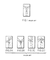
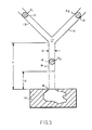
- FIG. 3 A particular exemplary embodiment of a mixing process that ensures an avoidance of instabilities and provides a substantially complete mixing is shown in FIG. 3 which uses a specific example of one of the various indirect impingement options, e.g. as shown in FIG. 2B, and further shows diagramatically the important parameters that require critical selection during the design of the mixing chamber.
- Such parameters are:
- the mixing length, L is the distance from the input of the outlet passage 16 at the region 17 where impingement and initial mixing of the inlet stream occurs to the point 18 at which external cooling essentially begins to take place, e.g. where final casting of the material takes place, such as at the surface of a mold 14 or, as described later, at a gas or liquid impingement location, or at an interface with a chilled block melt spinner, etc.
- free flow length means the length that the stream of mixed material travels in a substantially unconfined manner from a point 19 at which it leaves the outlet passage 16 (where it has been effectively confined by the passage) to the point 18 where final casting or other external cooling of the material starts to take place.
- the ratio of outlet cross-sectional area A0 to the total inlet cross-sectional area A i in the embodiment shown is such that
- L o is less than a length at which the free, or unconfined, mixture stream becomes unstable.
- the location at which the free stream i.e., the stream which leaves the outlet passage 16 of the mixing chamber at point 19
- the location at which the free stream i.e., the stream which leaves the outlet passage 16 of the mixing chamber at point 19
- the location at which the free stream is deemed to mean the location at which the previously confined column of fluid that has left the outlet passage 16 of the mixing chamber 14 starts developing corrugations that would ultimately lead to a breakage of the continuously flowing stream into discrete droplets.
- the above restriction on L o may not play an important role in those applications where it does not matter whether or not the stream becomes unstable as, for example, in the case of a mixing chamber which is directly linked to a holding tank, or tundish, of a continuous caster.
- the mixing length L in Eq. 2 would be the length of the stream from the impingement region 17 of the mixing region to the beginning of the holding tank, or tundish, of the continuous caster.
- the above relationships, as expressed in Eqs. (1) and (2) and in the length L o , can be used for numerous types of mixtures involving metals and metal alloys, as well as metals and metal alloys in combination with glass, polymers and/or ceramics, all of the ingredients being in a molten or slurry state.
- the mixed (and, if required, chemically reacted) mixture can be supplied from the mixing chamber to a mold, as described, for example, in U.S. Patent Nos. 4,278,622 and 4,279,843 or to a die caster as disclosed in U.S. Patent No. 4,786,730.
- FIGS. 4 and 5 depict exemplary systems utilizing rapid solidification processes (RSP) or techniques, which systems are directly linked to the outlet passage of the mixing chamber.
- RSP rapid solidification process
- FIGS. 4 and 5 depict exemplary systems utilizing rapid solidification processes (RSP) or techniques, which systems are directly linked to the outlet passage of the mixing chamber.
- rapid solidification process, or processes, (RSP) shall mean processes which achieve cooling rates of about 1000 o C/s, or greater.
- FIG. 4 depicts a system which couples the outlet passage 23 of the mixing chamber to an aotmizer nozzle 24.
- a gas, or liquid such as water, (referred to by arrows 25) can be made to flow at such an angle that it will, upon interaction with the mixture stream of liquid or slurry exiting from the outlet passage 23, cause the stream to break up into solidified powdered particles 27. Since such solidification does not take place instantaneously, the stream remains unsolidified for a short distance 26 effectively representing the distance L o .
- Each powder particle will contain many grains and can be individually considered in itself as a micro-composite material. By using such an approach, much faster cooling rates, of the order of 1000 o C/s, or greater, can be achieved.
- the powders which are so produced can them be pressed, extruded, or otherwise formed, in a conventional secondary operation, to manufacture finished bars, rods, or any other type of product or configuration.
- Another optional secondary operation using such powders is to deposit them into preforms using spray deposition techniques, for example, from which final products can be made by well-known machining or pressing techniques.
- FIG. 5 shows a chilled block melt spinning (CBMS) apparatus 28 which is directly linked to the outlet passage 23.
- CBMS chilled block melt spinning
- metallic ribbons 29 are produced, such ribbons being the result of cooling rates of the order of as high as 1,000,000 o C/s.
- a short distance from the outlet passage 23 to the chill block represents the length L o .
- Materials for mixing can be appropriately supplied to injection sections 20A and 20B of the particular systems discussed about with reference to FIGS. 4 and 5.
- heating and melting of relatively solid materials can take place to form molten slurry materials, or material already in a slurry or molten state can be initially so supplied.
- gas injection means 20C and 20D inject gas, at relatively high pressure, into sections 20A and 20B, respectively.
- the gas propels the materials in sections 20A and 20B through separate inlet channels 21A and 21B into a mixing region 22 designed in accordance with the relationships expressed in Egs. (1) and (2).
- L o is kept to a minimum.
- mixing regions 17 and 22 can, if desired, comprise one or more mixing regions as dictated by the specific nature of the material to be manufactured.
- the mixing streams are then cast by either impinging atomized air or water into the molten metal stream (FIG. 4) or by supplying the mixture to a chilled block melt spinner (FIG. 5).
Landscapes
- Engineering & Computer Science (AREA)
- Mechanical Engineering (AREA)
- Manufacture Of Alloys Or Alloy Compounds (AREA)
- Manufacture Of Metal Powder And Suspensions Thereof (AREA)
- Continuous Casting (AREA)
Applications Claiming Priority (2)
| Application Number | Priority Date | Filing Date | Title |
|---|---|---|---|
| US07/219,317 US4890662A (en) | 1988-07-15 | 1988-07-15 | Mixing and cooling techniques |
| US219317 | 1988-07-15 |
Publications (2)
| Publication Number | Publication Date |
|---|---|
| EP0352035A2 true EP0352035A2 (de) | 1990-01-24 |
| EP0352035A3 EP0352035A3 (de) | 1991-04-03 |
Family
ID=22818792
Family Applications (1)
| Application Number | Title | Priority Date | Filing Date |
|---|---|---|---|
| EP19890307175 Withdrawn EP0352035A3 (de) | 1988-07-15 | 1989-07-14 | Misch- und Kühltechniken |
Country Status (3)
| Country | Link |
|---|---|
| US (1) | US4890662A (de) |
| EP (1) | EP0352035A3 (de) |
| JP (1) | JPH0660362B2 (de) |
Cited By (2)
| Publication number | Priority date | Publication date | Assignee | Title |
|---|---|---|---|---|
| WO1998008095A1 (en) * | 1996-08-23 | 1998-02-26 | Abbott Laboratories | Procedure for attaching substances to particles |
| EP2112960A4 (de) * | 2007-01-23 | 2010-01-27 | Husky Injection Molding | Metallformsystem |
Families Citing this family (7)
| Publication number | Priority date | Publication date | Assignee | Title |
|---|---|---|---|---|
| US5071618A (en) * | 1988-08-30 | 1991-12-10 | Sutek Corporation | Dispersion strengthened materials |
| US5040594A (en) * | 1989-06-12 | 1991-08-20 | Ribbon Technology Corporation | Side feed tundish apparatus and method for the alloying and rapid solidification of molten materials |
| US5040593A (en) * | 1989-06-12 | 1991-08-20 | Ribbon Technology Corporation | Side feed tundish apparatus and method for the rapid solidification of molten materials |
| US6435854B1 (en) * | 1999-11-12 | 2002-08-20 | Eiji Sawa | Apparatus for mixing and injection molding thermosetting polyurethane |
| US10189057B2 (en) | 2016-07-08 | 2019-01-29 | General Electric Company | Powder removal enclosure for additively manufactured components |
| US10598438B2 (en) | 2016-07-27 | 2020-03-24 | General Electric Company | Support fixture |
| CN113134580B (zh) * | 2021-04-26 | 2022-05-20 | 兰州理工大学 | 金属半固态非枝晶浆料的制备方法以及制备装置 |
Family Cites Families (8)
| Publication number | Priority date | Publication date | Assignee | Title |
|---|---|---|---|---|
| US4279843A (en) * | 1979-09-24 | 1981-07-21 | Massachusetts Institute Of Technology | Process for making uniform size particles |
| US4278622A (en) * | 1979-09-24 | 1981-07-14 | Massachusetts Institute Of Technology | Method for forming metal, ceramic or polymer compositions |
| YU96681A (en) * | 1980-10-22 | 1983-12-31 | Allegheny Ludlum Steel | Device for casting metal bands |
| JPS6024247A (ja) * | 1983-07-18 | 1985-02-06 | Unitika Ltd | 液体急冷金属製品の連続製造方法 |
| EP0136866B1 (de) * | 1983-09-30 | 1991-12-27 | Kabushiki Kaisha Toshiba | Verfahren zur Herstellung einer niedrig schmelzenden Legierung zur Abdichtung von Leuchtstofflampen |
| DE3406036A1 (de) * | 1984-02-20 | 1985-08-22 | Mannesmann AG, 4000 Düsseldorf | Verfahren und einrichtung zum erzeugen von duennen metallstraengen aus metallschmelze, insbes. von stahlstraengen |
| US4784679A (en) * | 1986-10-31 | 1988-11-15 | Corning Glass Works | Method for making a layered glass article |
| US4706730A (en) * | 1987-01-27 | 1987-11-17 | Mixalloy Corporation | Mixing and casting apparatus |
-
1988
- 1988-07-15 US US07/219,317 patent/US4890662A/en not_active Expired - Fee Related
-
1989
- 1989-07-14 JP JP1182367A patent/JPH0660362B2/ja not_active Expired - Lifetime
- 1989-07-14 EP EP19890307175 patent/EP0352035A3/de not_active Withdrawn
Cited By (2)
| Publication number | Priority date | Publication date | Assignee | Title |
|---|---|---|---|---|
| WO1998008095A1 (en) * | 1996-08-23 | 1998-02-26 | Abbott Laboratories | Procedure for attaching substances to particles |
| EP2112960A4 (de) * | 2007-01-23 | 2010-01-27 | Husky Injection Molding | Metallformsystem |
Also Published As
| Publication number | Publication date |
|---|---|
| JPH0660362B2 (ja) | 1994-08-10 |
| JPH02153031A (ja) | 1990-06-12 |
| US4890662A (en) | 1990-01-02 |
| EP0352035A3 (de) | 1991-04-03 |
Similar Documents
| Publication | Publication Date | Title |
|---|---|---|
| US4540546A (en) | Method for rapid solidification processing of multiphase alloys having large liquidus-solidus temperature intervals | |
| DE68917132T2 (de) | Verfahren und vorrichtung zum zerstäuben einer metallschmelze. | |
| US5749938A (en) | Production of powder | |
| DE60133546T2 (de) | Schnelles abkühlungssystem zur herstlleung von kokillen, druckgiessformen und ähnlichen werkzeugen | |
| US4890662A (en) | Mixing and cooling techniques | |
| EP1493517B1 (de) | Verfahren zur Herstellung von mit Nanopartikeln verstärkten Materialien sowie hergestellte Formkörper | |
| EP1042093B1 (de) | Verfahren und vorrichtung zur herstellung feiner pulver durch zerstäubung von schmelzen mit gasen | |
| DE68910072T2 (de) | Verschleissfeste Beschichtung und Verfahren zu ihrer Herstellung. | |
| US4818279A (en) | Method and device for the granulation of a molten material | |
| ZA200405477B (en) | Method for producing particle shaped material | |
| JP4562347B2 (ja) | 液体鋼の連続鋳造方法と装置 | |
| US4706730A (en) | Mixing and casting apparatus | |
| KR100442155B1 (ko) | 마그네슘 합금부재용 재료 및 마그네슘 합금부재의 제조방법 | |
| JP3394550B2 (ja) | ビスフェノールaプリルの製造方法 | |
| JPH0754019A (ja) | 多段階分裂及び急冷による粉末の作製法 | |
| Suh | Orthonormal processing of metals. Part 1: Concept and theory | |
| JPH08209207A (ja) | 金属粉末の製造方法 | |
| EP4019167A1 (de) | Zerstäubung von metallischen schmelzen unter verwendung von flüssigem co2 | |
| US4626410A (en) | Method of making composite material of matrix metal and fine metallic particles dispersed therein | |
| US5040594A (en) | Side feed tundish apparatus and method for the alloying and rapid solidification of molten materials | |
| JPH05105918A (ja) | 微細分散複合粉末の製造方法および製造装置 | |
| RU2035522C1 (ru) | Способ получения композиционного материала с металлической матрицей | |
| JPS63260664A (ja) | 分散強化材の製造法 | |
| JP2911971B2 (ja) | 金属粉末製造用高圧水噴射管及び見掛け密度が低い金属粉末の製造方法 | |
| JPS62182236A (ja) | 粒子分散金属の製造方法 |
Legal Events
| Date | Code | Title | Description |
|---|---|---|---|
| PUAI | Public reference made under article 153(3) epc to a published international application that has entered the european phase |
Free format text: ORIGINAL CODE: 0009012 |
|
| AK | Designated contracting states |
Kind code of ref document: A2 Designated state(s): BE DE FR GB IT NL SE |
|
| PUAL | Search report despatched |
Free format text: ORIGINAL CODE: 0009013 |
|
| AK | Designated contracting states |
Kind code of ref document: A3 Designated state(s): BE DE FR GB IT NL SE |
|
| 17P | Request for examination filed |
Effective date: 19910910 |
|
| 17Q | First examination report despatched |
Effective date: 19930630 |
|
| STAA | Information on the status of an ep patent application or granted ep patent |
Free format text: STATUS: THE APPLICATION IS DEEMED TO BE WITHDRAWN |
|
| 18D | Application deemed to be withdrawn |
Effective date: 19950201 |