EP0352058A2 - Wärmeisolierte Brennkraftmaschine - Google Patents
Wärmeisolierte Brennkraftmaschine Download PDFInfo
- Publication number
- EP0352058A2 EP0352058A2 EP89307248A EP89307248A EP0352058A2 EP 0352058 A2 EP0352058 A2 EP 0352058A2 EP 89307248 A EP89307248 A EP 89307248A EP 89307248 A EP89307248 A EP 89307248A EP 0352058 A2 EP0352058 A2 EP 0352058A2
- Authority
- EP
- European Patent Office
- Prior art keywords
- heat insulating
- combustion chamber
- thin
- block
- cylinder
- Prior art date
- Legal status (The legal status is an assumption and is not a legal conclusion. Google has not performed a legal analysis and makes no representation as to the accuracy of the status listed.)
- Granted
Links
- 238000002485 combustion reaction Methods 0.000 claims abstract description 124
- 229910010293 ceramic material Inorganic materials 0.000 claims abstract description 41
- 239000000446 fuel Substances 0.000 claims abstract description 28
- 239000000463 material Substances 0.000 claims abstract description 20
- 238000002347 injection Methods 0.000 claims abstract description 11
- 239000007924 injection Substances 0.000 claims abstract description 11
- 238000004891 communication Methods 0.000 claims description 17
- 230000006854 communication Effects 0.000 claims description 17
- 229910052581 Si3N4 Inorganic materials 0.000 claims description 9
- 239000011810 insulating material Substances 0.000 claims description 9
- HQVNEWCFYHHQES-UHFFFAOYSA-N silicon nitride Chemical group N12[Si]34N5[Si]62N3[Si]51N64 HQVNEWCFYHHQES-UHFFFAOYSA-N 0.000 claims description 9
- 229910010271 silicon carbide Inorganic materials 0.000 claims description 8
- HBMJWWWQQXIZIP-UHFFFAOYSA-N silicon carbide Chemical group [Si+]#[C-] HBMJWWWQQXIZIP-UHFFFAOYSA-N 0.000 claims description 8
- 229910000505 Al2TiO5 Inorganic materials 0.000 claims description 7
- NJLLQSBAHIKGKF-UHFFFAOYSA-N dipotassium dioxido(oxo)titanium Chemical group [K+].[K+].[O-][Ti]([O-])=O NJLLQSBAHIKGKF-UHFFFAOYSA-N 0.000 claims description 7
- AABBHSMFGKYLKE-SNAWJCMRSA-N propan-2-yl (e)-but-2-enoate Chemical group C\C=C\C(=O)OC(C)C AABBHSMFGKYLKE-SNAWJCMRSA-N 0.000 claims description 7
- GROMGGTZECPEKN-UHFFFAOYSA-N sodium metatitanate Chemical group [Na+].[Na+].[O-][Ti](=O)O[Ti](=O)O[Ti]([O-])=O GROMGGTZECPEKN-UHFFFAOYSA-N 0.000 claims description 3
- 241001052209 Cylinder Species 0.000 claims 1
- 239000000779 smoke Substances 0.000 abstract description 8
- 239000008246 gaseous mixture Substances 0.000 abstract description 4
- 230000007423 decrease Effects 0.000 description 9
- 238000010276 construction Methods 0.000 description 6
- 229940090044 injection Drugs 0.000 description 6
- 239000003054 catalyst Substances 0.000 description 3
- 238000005229 chemical vapour deposition Methods 0.000 description 3
- 229910000510 noble metal Inorganic materials 0.000 description 3
- KDLHZDBZIXYQEI-UHFFFAOYSA-N Palladium Chemical compound [Pd] KDLHZDBZIXYQEI-UHFFFAOYSA-N 0.000 description 2
- MCMNRKCIXSYSNV-UHFFFAOYSA-N Zirconium dioxide Chemical compound O=[Zr]=O MCMNRKCIXSYSNV-UHFFFAOYSA-N 0.000 description 2
- 239000000919 ceramic Substances 0.000 description 2
- 238000004880 explosion Methods 0.000 description 2
- 229910052751 metal Inorganic materials 0.000 description 2
- 239000002184 metal Substances 0.000 description 2
- BASFCYQUMIYNBI-UHFFFAOYSA-N platinum Chemical compound [Pt] BASFCYQUMIYNBI-UHFFFAOYSA-N 0.000 description 2
- OKTJSMMVPCPJKN-UHFFFAOYSA-N Carbon Chemical compound [C] OKTJSMMVPCPJKN-UHFFFAOYSA-N 0.000 description 1
- 239000004215 Carbon black (E152) Substances 0.000 description 1
- VYPSYNLAJGMNEJ-UHFFFAOYSA-N Silicium dioxide Chemical compound O=[Si]=O VYPSYNLAJGMNEJ-UHFFFAOYSA-N 0.000 description 1
- 229910052799 carbon Inorganic materials 0.000 description 1
- 238000005266 casting Methods 0.000 description 1
- 239000011195 cermet Substances 0.000 description 1
- 239000011248 coating agent Substances 0.000 description 1
- 238000000576 coating method Methods 0.000 description 1
- 239000000567 combustion gas Substances 0.000 description 1
- 230000006866 deterioration Effects 0.000 description 1
- 239000000835 fiber Substances 0.000 description 1
- 239000012530 fluid Substances 0.000 description 1
- 239000007789 gas Substances 0.000 description 1
- 238000010438 heat treatment Methods 0.000 description 1
- 229930195733 hydrocarbon Natural products 0.000 description 1
- 150000002430 hydrocarbons Chemical class 0.000 description 1
- 239000012212 insulator Substances 0.000 description 1
- 229910052575 non-oxide ceramic Inorganic materials 0.000 description 1
- 239000011224 oxide ceramic Substances 0.000 description 1
- 229910052763 palladium Inorganic materials 0.000 description 1
- 229910052697 platinum Inorganic materials 0.000 description 1
- 230000002265 prevention Effects 0.000 description 1
- 230000005855 radiation Effects 0.000 description 1
- 229910052703 rhodium Inorganic materials 0.000 description 1
- 239000010948 rhodium Substances 0.000 description 1
- MHOVAHRLVXNVSD-UHFFFAOYSA-N rhodium atom Chemical compound [Rh] MHOVAHRLVXNVSD-UHFFFAOYSA-N 0.000 description 1
- 238000000926 separation method Methods 0.000 description 1
- 230000035939 shock Effects 0.000 description 1
- 229910052710 silicon Inorganic materials 0.000 description 1
- 239000010703 silicon Substances 0.000 description 1
- 229910052814 silicon oxide Inorganic materials 0.000 description 1
Images
Classifications
-
- F—MECHANICAL ENGINEERING; LIGHTING; HEATING; WEAPONS; BLASTING
- F02—COMBUSTION ENGINES; HOT-GAS OR COMBUSTION-PRODUCT ENGINE PLANTS
- F02B—INTERNAL-COMBUSTION PISTON ENGINES; COMBUSTION ENGINES IN GENERAL
- F02B19/00—Engines characterised by precombustion chambers
- F02B19/16—Chamber shapes or constructions not specific to sub-groups F02B19/02 - F02B19/10
- F02B19/165—The shape or construction of the pre-combustion chambers is specially adapted to be formed, at least in part, of ceramic material
-
- F—MECHANICAL ENGINEERING; LIGHTING; HEATING; WEAPONS; BLASTING
- F02—COMBUSTION ENGINES; HOT-GAS OR COMBUSTION-PRODUCT ENGINE PLANTS
- F02B—INTERNAL-COMBUSTION PISTON ENGINES; COMBUSTION ENGINES IN GENERAL
- F02B77/00—Component parts, details or accessories, not otherwise provided for
- F02B77/11—Thermal or acoustic insulation
-
- F—MECHANICAL ENGINEERING; LIGHTING; HEATING; WEAPONS; BLASTING
- F02—COMBUSTION ENGINES; HOT-GAS OR COMBUSTION-PRODUCT ENGINE PLANTS
- F02B—INTERNAL-COMBUSTION PISTON ENGINES; COMBUSTION ENGINES IN GENERAL
- F02B27/00—Use of kinetic or wave energy of charge in induction systems, or of combustion residues in exhaust systems, for improving quantity of charge or for increasing removal of combustion residues
- F02B27/04—Use of kinetic or wave energy of charge in induction systems, or of combustion residues in exhaust systems, for improving quantity of charge or for increasing removal of combustion residues in exhaust systems only, e.g. for sucking-off combustion gases
-
- F—MECHANICAL ENGINEERING; LIGHTING; HEATING; WEAPONS; BLASTING
- F05—INDEXING SCHEMES RELATING TO ENGINES OR PUMPS IN VARIOUS SUBCLASSES OF CLASSES F01-F04
- F05C—INDEXING SCHEME RELATING TO MATERIALS, MATERIAL PROPERTIES OR MATERIAL CHARACTERISTICS FOR MACHINES, ENGINES OR PUMPS OTHER THAN NON-POSITIVE-DISPLACEMENT MACHINES OR ENGINES
- F05C2201/00—Metals
- F05C2201/02—Light metals
- F05C2201/021—Aluminium
-
- Y—GENERAL TAGGING OF NEW TECHNOLOGICAL DEVELOPMENTS; GENERAL TAGGING OF CROSS-SECTIONAL TECHNOLOGIES SPANNING OVER SEVERAL SECTIONS OF THE IPC; TECHNICAL SUBJECTS COVERED BY FORMER USPC CROSS-REFERENCE ART COLLECTIONS [XRACs] AND DIGESTS
- Y02—TECHNOLOGIES OR APPLICATIONS FOR MITIGATION OR ADAPTATION AGAINST CLIMATE CHANGE
- Y02T—CLIMATE CHANGE MITIGATION TECHNOLOGIES RELATED TO TRANSPORTATION
- Y02T10/00—Road transport of goods or passengers
- Y02T10/10—Internal combustion engine [ICE] based vehicles
- Y02T10/12—Improving ICE efficiencies
Definitions
- This invention relates to an heat insulating engine consisting mainly of a ceramic material and provided with an auxiliary combustion chamber.
- a conventional heat insulating engine utilizing a ceramic material as a heat resisting material is disclosed in, for example, Japanese Patent Laid-Open No. 46317/1984.
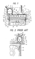
- the parts of a combustion chamber in the internal combustion engine will now be described with reference to Fig. 2.
- the parts of the combustion chamber in the internal combustion engine include parts constituting an auxiliary combustion chamber, a cylinder head 41, a cylinder liner 44, a piston 45, and parts of a combustion chamber which constitute the inner surface of the combustion chamber, and these parts are formed out of a ceramic material having excellent heat insulating characteristics.
- the cylinder head 41 is combined with a cylinder block 42 via a gasket 43, and the cylinder liner 44 is fixed to the cylinder block 42.
- a vortex chamber 47 formed in the cylinder head 41 consists of upper and lower vortex chamber members 48, 49 fitted in the cylinder head 41.
- the lower vortex chamber 49 is provided with an ejection port 50 which communicates the vortex chamber 47 and a main combustion chamber 46 with each other.
- a fuel injection nozzle 52 and a glow plug 53 are provided in the cylinder head 41.
- the upper and lower vortex chamber members 48, 49 are formed as combustion chamber parts out of a ceramic material of a non-oxide of silicon, such as a silicon nitride ceramic material and a silicon carbide ceramic material.
- the material of the surfaces defining the vortex chamber 47 and ejection port 50 is converted into a silicon oxide ceramic material due to the heating of the non-oxide ceramic material to a high temperature.
- a thin layer of a catalyst of a noble metal, such as platinum, rhodium and palladium is formed on each of these surfaces by spattering. Owing to such a construction, these combustion chamber parts prevent the separation of a thin layer 51 of a noble metal catalyst, minimizes the deterioration of the catalyst and reduces an unburnt hydrocarbon content of an exhaust gas.
- a noble metal such as platinum, rhodium and palladium
- the wall thickness is increased for the purpose of meeting the requirements.
- the portions of such an engine which face the combustion chamber can be formed so that they can withstand a high-temperature combustion gas, by making them of a ceramic material, such as silicon nitride having high thermal resistance and thermal shock resistance and excellent heat insulating characteristics.
- the wall thickness is too large, the thermal capacity of the wall surface increases. Consequently, the suction air receives the heat energy accumulated on the inner surface, and is thermally expanded, so that the suction efficiency decreases.
- the thicknesses of the constituted parts of the combustion chamber in the internal combustion engine disclosed in Japanese Patent Laid-Open No. 46317/1984 referred to previously are all large, and the thin layer 51 consists of a noble metal as mentioned above.
- the upper and lower vortex chambers 48, 49 are formed out of a ceramic material of silicon nitride or silicon carbide which has a high heat resistance and not so good heat insulating characteristics. Therefore, the thermal capacity of the surface of each part of the combustion chamber becomes high, and the thermal capacity of the parts exposed to a high temperature cannot be reduced to a low level. This makes it impossible to prevent a decrease of the suction efficiency. Moreover, it is impossible in this construction to speedily carry out the mixing of atomized fuel with air.
- a primary object of the present invention is to solve the problems referred to above, and provide a heat insulating engine, in which the ceramic members constituting the inner surfaces of main and auxiliary combustion chambers are formed by thin members the inner surfaces of which are covered with a heat insulating material, so as to minimize the thermal capacity of these inner surfaces, this enabling the suction efficiency of the engine to be improved, the mixing of atomized fuel with air to be done speedily owing to the improvement of the suction efficiency, the combustion temperature to be increased in a short period of time, the combustion time in a smoke generating combustion zone to be minimized whereby the generation of smoke is suppressed, the gaseous mixture to be then to be blown out as a swirled flame from the auxiliary combustion chamber into the main combustion chamber whereby a sudden decrease of the equivalent ratio of the fuel and a decrease of the combustion temperature are effected, and the combustion in a NOx generating combustion zone to be thereby prevented whereby the generation of NOx is suppressed.
- Another object of the present invention is to provide a heat insulating engine, in which, in order to prevent a decrease of the strength of the auxiliary and main combustion chambers, which is ascribed to the reduction of the thickness of the high-density ceramic material constituting the inner surfaces of these combustion chambers, a layer of heat insulating material is formed on the outer surface of the thin members constituting these inner surfaces, so as to thermally insulating the same inner surfaces and increase the strength of the walls of the combustion chambers.
- Still another object of the present invention is to provide a heat insulating engine, in which an auxiliary combustion chamber which has a thin layer of a high-density ceramic material formed on the inner surface of an auxiliary combustion chamber block consisitng of a material of a low heat conductivity, and which is provided with a fuel injection nozzle, is communicated via a communication port with a main combustion chamber consisting of a thin wall of a high-density ceramic material and fitted in a cylinder head via a heat insulating material.
- a further object of the present invention is to provide a heat insulating engine, in which a main combustion chamber consists of a unitary combination of a thin lower head-surface member and thin liner members which are attached to the lower surface of a cylinder head and composed of a high-density ceramic material, the thin liner members being fitted in the portions of the cylinder head which are on the upper side of a cylinder liner, which consists of a material of a low heat transfer rate, to thermally insulate the thin liner member, improve the strength of the same member, a part to which a load is imparted, and prevent the thin member, a wall surface member, from being destroyed even when the temperature and pressure in the interior of the main combustion chamber are high.
- a further object of the present invention is to provide a heat insulating engine, in which a main combustion chamber consists of a unitary combination of a thin lower head-surface member and thin liner members which are attached to the lower surface of a cylinder head and composed of a high-density ceramic material, the thin liner members being fitted in the portions of the cylinder head which are on the upper side of a cylinder liner, which consists of a material of a low heat transfer rate, to thermally insulate the thin liner member and improve the strength of the same member, a part to which a load is imparted, the portion of a piston head which is opposed to the main combustion chamber being provided with a thin member of a high-density ceramic material so as to reduce to a low level the thermal capacity of the surfaces of all walls that form the main combustion chamber.
- the suction efficiency of the engine can be improved by designing the engine so that the temperature of the inner surfaces varies in accordance with that of the suction air.
- the thermal capacity of the surface of the wall of the combustion chamber is small, the thermal energy is not absorbed so much in the inner surface.
- the temperature of the wall surface increases immediately due to the combustion of a gaseous mixture, and the rate of radiation of heat from the inner surface decreases, the thermal energy being recovered by an energy recovering unit, which is provided on the downstream side of the combustion chamber, and effectively utilized.
- a smoke generating zone in which smoke occurs lies in the portion of the combustion zone which has a high fuel equivalent ratio, a fuel-air ratio, and a low combustion temperature.
- a NOx generating zone in which NOx occurs lies in the portion of the combustion zone which has a low fuel equivalent ratio and a high combustion temperature. Accordingly, it is preferable that the combustion of a fuel in a heat insulating engine be carried out in the portion of a combustion zone thereof which excludes the smoke generating combustion zone and NOx generating combustion zone, or that the combustion of the fuel in these two undesirable combustion zones by speedily finished.
- the heat insulating engine according to the present invention has a construction which seeks to meet the conditions mentioned above. Since the thermal capacity of the inner surface of the auxiliary combustion chamber and the volume of the combustion chamber are small, the fuel is injected from the fuel injection nozzle into the auxiliary combustion chamber to immediately set the fuel equivalent ratio to a fuel enriching level. Especially, since the thermal capacity of the inner surface of the auxiliary combustion chamber and the volume of the chamber are small, the mixing of the atomized fuel with air is done speedily, and the temperature of the resultant gaseous mixture is increased in a short period of time.
- the combustion in the smoke generating combustion zone which is determined by the fuel equivalent ratio and combustion temperature, is speedily finished, and the flame is blown out in a swirled state from the auxiliary combustion chamber into the main combustion chamber, so that the fuel equivalent ratio decreases suddenly or in a short period of time in the main combustion chamber.
- the temperature of the main combustion chamber varies in strict accordance with that of the suction air, suction rate of the air introduced into the engine does not decrease. Accordingly, the combustion temperature drops as the fuel equivalent ratio lowers. This enables the prevention of combustion in the NOx generating.
- the heat insulating engine according to the present invention enables combustion to be carried out in the auxiliary and main combustion chamber with the generation of smoke and NOx suppressed.
- Fig. 1 is a sectional view of an embodiment of the heat insulating engine according to the present invention.
- Fig. 2 is a sectional view of an example of a diesel engine in which conventional parts of a combustion chamber are incorporated.
- Fig. 1 is a schematic section showing the construction of a heat insulating engine embodying the present invention.
- This heat insulating engine is constructed so that an auxiliary combustion chamber 4 which has an auxiliary combustion chamber block of a material of a low heat transfer rate, the inner surface of which is formed by a thin member 8 consisting of a high-density ceramic material, and which is provided with a fuel injection nozzle 9, is communicated with a main combustion chamber 5 consisting of a thin member composed of a high-density ceramic material and fitted in a cylinder head 10 via heat insulating members.
- the cylinder head 10 is made of a casting, and an upper cylinder liner 1 is fitted in the cylinder head 10 via ring-shaped heat insulating gaskets 13, 14, a heat insulating air layer 11 being formed between the inner circumferential surface of the cylinder head 10 and the outer circumferential surface of the upper cylinder liner 1.
- a head liner 15 consisting of thin liner members 3 combined unitarily with a thin member 2 on the lower surface of the cylinder head is made of thin members of a high-density ceramic material, such as silicon nitride and silicon carbide, and fitted in the upper cylinder liner 1 to constitute the surface of the main combustion chamber 5.
- Heat insulating layers 12 are formed between the lower surface of the cylinder head 10 and thin member 2, which is formed unitarily with the head liner 15, via heat insulating gaskets 39.
- the thin liner members 3 constituting the head liner 15 is press fitted closely in the upper cylinder liner 1 consisting of a heat insulating material of a low heat transfer rate, such as aluminum titanate and potassium titanate so as to improve the strength of the thin liner members 3 and heat insulating characteristics of the main combustion chamber 5. Accordingly, the head liner 15 consisting of the thin liner members 3 formed unitarily with the thin member 2 on the lower surface of the cylinder head can be formed to a smallest possible thermal capacity.
- the thin member 2 on the lower surface of the cylinder head is provided with a communication port 17, which is communicated with a communication port 16 of the auxiliary combustion chamber 4, and suction and exhaust ports 18 (only one of them is shown in the drawing) in which suction and exhaust valves 21 are installed.
- Each valve 21 is set on a valve seat 19 provided in the cylinder head 10.
- Each of the suction and exhaust ports 18 is formed in a position determined correspondingly to the valve seat 19.
- the lower end surfaces of the thin liner members 3 in the head liner 15 are joined to a cylinder liner 22 via a heat insulating gasket 24.
- the cylinder liner 22 is fitted in a cylinder in the cylinder block 23, and the cylinder head 10 is fixed to the cylinder block 23 via a gasket 40.
- the auxiliary combustion chamber 4 has construction similar to the main combustion chamber 5, and is formed by fixing a thin member 8 consisting of a high-density ceramic material to the inner circumferential surface of an auxiliary combustion chamber block formed out of a material of a low heat transfer rate by combining the upper block 6 of the auxiliary combustion chamber with the lower block 7 thereof at a contact portion 38 (intermediate portion in the drawing) of the end surfaces thereof.
- the upper block 6 of the auxiliary combustion chamber 4 is provided with the fuel injection nozzle 9, and the lower block 7 thereof the communication port 16.
- These upper and lower blocks 6, 7 are formed out of a heat insulating material having a low heat transfer rate and a low Young's modulus, such as aluminum titanate, potassium titanate and sodium titanate.
- a thin member 8 consisting of a high-density ceramic material, such as silicon nitride and silicon carbide is applied to the inner surface of the auxiliary combustion chamber 4.
- the fixing of the thin member 8 to the inner surfaces of the upper and lower blocks 6, 7 of the auxiliary combustion chamber can be done by, for example, the chemical vapor deposition (CVD) of the mentioned material on these surfaces or coating these surfaces with the mentioned material.
- the thin member 8 consisting of a high-density ceramic material, such as silicon nitride and silicon carbide is attached to the inner surface of the communication port 16 in the same manner as in the auxiliary combustion chamber 4, which communication port 16 communicates the auxiliary and main combustion chambers 4, 5 with each other. This enables the inner surface of the auxiliary combustion chamber, in other words, the thin member 8 to be formed to a smallest possible thermal capacity.
- the communication port 16 which communicates the auxiliary and main combustion chambers 4, 5 with each other is extended diagonally so that the swirling of a flame is promoted in the auxiliary combustion chamber 4 or main combustion chamber 5 in accordance with the entry and discharge of a fluid.
- the axis of the communication port 16 and that of the fuel injection nozzle 9 are set out of alignment and in a mutually opposed state.
- the thin liner members 3 in the upper cylinder liner 1 and a piston 20 reciprocatingly moved in the cylinder liner 22 are formed in a heat insulating manner.
- This piston 20 has a piston head, and a piston skirt 30 fixed to the piston head.
- the piston head has a piston head body 29, a thin head member 25 consisting of a high-density ceramic material attached to the side of the piston head body which is opposed to the main combustion chamber 5, and heat insulating members 27, 28 provided between the piston head body 29 and thin head member 25.
- This thin head member 25 is formed out of a high-density ceramic material, such as silicon nitride and silicon carbide, and to a thickness of, for example, around 1 mm or not more than 1 mm.
- the thin head member 25 is provided on its outer circumferential surface with a thin ring member 31 consisting of the same material and fixed thereto by the chemical vapor deposition.
- the thin head member 25 is fixed to the piston head body 29 by the ring member 31 via the heat insulating members 27, 28.
- the ring member 31 is provided on its inner circumferential surface with a stepped portion 35, and the piston head body 29 is fitted in the ring member 31 so that an outer circumferential portion 36 of the piston head body 29 engages the ring member 31.
- the piston head body 29 has a mounting boss 34 at the central portion thereof, and is formed out of a material having a coefficient of thermal expansion substantially equal to that of a ceramic material, a high strength and a comparatively high Young's modulus, for example, cermet and a metal.
- the surface of this piston head body 29 which is on the side of the combustion chamber 5 is formed flat, and the piston skirt 30 is provided at its central portion with a mounting hole 26 in which the mounting boss 34 of the piston head body 29 is fitted.
- the mounting boss 34 of the piston head body 29 is fitted in the central mounting hole 26 in the piston skirt 30, and a metal ring 33 is inserted in a deformed state into both a groove formed in the mounting boss 34 and a groove formed in the inner surface of the central mounting hole 26, the piston head body 29 being engaged in a pressed state with the piston skirt 30.
- a heat insulating air layer 32 is formed between the piston head body 29 and piston skirt 30.
- the heat insulating members 27, 28 provided between the thin head member 25 and piston head body 29 consist of a material, such as potassium titanate, aluminum titanate, whiskers of potassium titanate and zirconia fiber. These members 27, 28 function as excellent heat insulators and also as structural members for receiving the pressure applied to the thin head member 25 at an explosion stroke. Since the piston head body 29 is engaged in a pressed state with the piston skirt 30, the outer circumferential portion 36 of the piston head body 29 is pressed against the stepped portion 35 of the ring member 31, and the ring member 31 against the circumferential portion of the piston skirt 30. In this embodiment, a carbon seal 37, a kind of gasket, is provided so as to seal the ring member 31 and piston skirt 30.
- the compressive force occurring due to an explosion be received equally by the heat insulating members 27, 28 of aluminum titanate, potassium titanate or sodium titanate. Accordingly, the surface of the piston head body 29 which is on the side of the main combustion chamber 5, and the thin head member 25 are formed flat.
Landscapes
- Engineering & Computer Science (AREA)
- Chemical & Material Sciences (AREA)
- Combustion & Propulsion (AREA)
- Mechanical Engineering (AREA)
- General Engineering & Computer Science (AREA)
- Ceramic Engineering (AREA)
- Physics & Mathematics (AREA)
- Acoustics & Sound (AREA)
- Combustion Methods Of Internal-Combustion Engines (AREA)
- Cylinder Crankcases Of Internal Combustion Engines (AREA)
Applications Claiming Priority (2)
| Application Number | Priority Date | Filing Date | Title |
|---|---|---|---|
| JP63180250A JP2718071B2 (ja) | 1988-07-21 | 1988-07-21 | 副室式断熱エンジン |
| JP180250/88 | 1988-07-21 |
Publications (3)
| Publication Number | Publication Date |
|---|---|
| EP0352058A2 true EP0352058A2 (de) | 1990-01-24 |
| EP0352058A3 EP0352058A3 (en) | 1990-03-28 |
| EP0352058B1 EP0352058B1 (de) | 1992-10-14 |
Family
ID=16079985
Family Applications (1)
| Application Number | Title | Priority Date | Filing Date |
|---|---|---|---|
| EP89307248A Expired - Lifetime EP0352058B1 (de) | 1988-07-21 | 1989-07-18 | Wärmeisolierte Brennkraftmaschine |
Country Status (4)
| Country | Link |
|---|---|
| US (1) | US4998517A (de) |
| EP (1) | EP0352058B1 (de) |
| JP (1) | JP2718071B2 (de) |
| DE (2) | DE352058T1 (de) |
Cited By (7)
| Publication number | Priority date | Publication date | Assignee | Title |
|---|---|---|---|---|
| EP0395406A1 (de) * | 1989-04-26 | 1990-10-31 | Isuzu Ceramics Research Institute Co., Ltd. | Wärmeisolierter Viertakt-Verbrennungsmotor mit Vorkammern |
| EP0420456A1 (de) * | 1989-09-29 | 1991-04-03 | Isuzu Motors Limited | Motor mit wärmeisolierter Wirbelkammer |
| EP0420641A1 (de) * | 1989-09-29 | 1991-04-03 | Isuzu Motors Limited | Wärmeisolierter Motor mit Wirbelkammer |
| EP0420642A1 (de) * | 1989-09-29 | 1991-04-03 | Isuzu Motors Limited | Alkoholbrennkraftmaschine mit Vorkammer |
| DE19524015A1 (de) * | 1994-09-29 | 1996-04-04 | Ford Werke Ag | Wärmekraftmaschinen - Kolben/Brennkammeranordnung |
| US5522371A (en) * | 1993-10-25 | 1996-06-04 | Isuzu Ceramics Research Institute Co., Ltd. | Thermal insulation engine |
| EP3919727A1 (de) * | 2016-07-14 | 2021-12-08 | Yanmar Power Technology Co., Ltd. | Brennkraftmaschine |
Families Citing this family (16)
| Publication number | Priority date | Publication date | Assignee | Title |
|---|---|---|---|---|
| JP2552906B2 (ja) * | 1988-08-05 | 1996-11-13 | 株式会社いすゞセラミックス研究所 | 断熱エンジン |
| JP2790866B2 (ja) * | 1989-08-24 | 1998-08-27 | 日産自動車株式会社 | 燃焼装置の排気通路 |
| JP2819055B2 (ja) * | 1990-07-07 | 1998-10-30 | 株式会社いすゞセラミックス研究所 | 副燃焼室式断熱エンジン |
| JP2653226B2 (ja) * | 1990-08-08 | 1997-09-17 | 日産自動車株式会社 | 2ストロークディーゼルエンジン |
| CA2056236C (en) * | 1991-11-26 | 2001-08-21 | Gary D. Webster | Internal combustion engine with high temperature variable geometry pre-combustion chamber |
| JP3048476B2 (ja) * | 1992-09-29 | 2000-06-05 | 株式会社いすゞセラミックス研究所 | リフト量可変制御弁を備えた副室式ガスエンジン |
| EP0645529B1 (de) * | 1993-09-28 | 1998-01-07 | Isuzu Ceramics Research Institute Co., Ltd. | Maschine mit thermischer Isolation |
| US6058918A (en) * | 1994-08-03 | 2000-05-09 | Financieres C. Vernes | Combustion catalyst device for an internal combustion engine |
| US5562079A (en) * | 1995-02-23 | 1996-10-08 | The United States Of America As Represented By The Administrator Of The U.S. Environmental Protection Agency | Low-temperature, near-adiabatic engine |
| US6170441B1 (en) | 1998-06-26 | 2001-01-09 | Quantum Energy Technologies | Engine system employing an unsymmetrical cycle |
| CN100410508C (zh) * | 2004-11-16 | 2008-08-13 | 天津大学 | 压缩点火气体燃料发动机燃烧系统及其复合供气方法 |
| US20090071434A1 (en) * | 2007-09-19 | 2009-03-19 | Macmillan Shaun T | Low heat rejection high efficiency internal combustion engine |
| DE102009019377A1 (de) | 2009-04-29 | 2010-11-11 | Herzog, Hans-Georg, Dr. Ing. | Partikelfreier Dampf-Dieselmotor |
| US9567896B2 (en) * | 2013-01-28 | 2017-02-14 | Sonex Research, Inc. | Method for modifying combustion chamber in a reciprocating piston internal combustion engine and resulting engine |
| KR102702908B1 (ko) * | 2018-03-20 | 2024-09-05 | 리달 퍼포먼스 머티리얼즈 (유에스) 인크. | 적은 연기 및 냄새를 갖는 고온 열음향 배리어 |
| CN108730015B (zh) * | 2018-05-22 | 2020-03-06 | 上海交通大学 | 一种带副燃烧室的发动机 |
Family Cites Families (13)
| Publication number | Priority date | Publication date | Assignee | Title |
|---|---|---|---|---|
| DE2804562A1 (de) * | 1978-02-03 | 1979-08-09 | Volkswagenwerk Ag | Mehrzylindrige brennkraftmaschine |
| DE2919743A1 (de) * | 1979-05-16 | 1980-11-27 | Volkswagenwerk Ag | Brennraum fuer brennkraftmaschinen |
| SE433376B (sv) * | 1979-10-22 | 1984-05-21 | Saab Scania Ab | Kolvmotor med vermeisolerat forbrenningsrum |
| DE3133209C2 (de) * | 1981-08-21 | 1985-04-25 | MTU Motoren- und Turbinen-Union München GmbH, 8000 München | Hohler Verbundkörper, insbesondere Umdrehungskörper und Verfahren zu seiner Herstellung |
| JPS58139522U (ja) * | 1982-03-17 | 1983-09-20 | ヤンマーディーゼル株式会社 | 内燃機関の燃焼室 |
| JPS5946317A (ja) * | 1982-09-07 | 1984-03-15 | Toyota Motor Corp | 内燃機関の燃焼室部品 |
| US4616611A (en) * | 1984-10-16 | 1986-10-14 | Ngk Insulators, Ltd. | Precombustion chamber construction of internal combustion engine |
| JPS61142320A (ja) * | 1984-12-15 | 1986-06-30 | Mitsubishi Heavy Ind Ltd | デイ−ゼル機関の燃焼室 |
| JPS61178514A (ja) * | 1985-02-02 | 1986-08-11 | Toyota Motor Corp | セラミツク製副燃焼室式デイ−ゼルエンジン |
| US4738227A (en) * | 1986-02-21 | 1988-04-19 | Adiabatics, Inc. | Thermal ignition combustion system |
| JPH066891B2 (ja) * | 1987-05-30 | 1994-01-26 | いすゞ自動車株式会社 | 断熱エンジンの構造 |
| US4796572A (en) * | 1987-06-01 | 1989-01-10 | The United States Of America As Represented By The Secretary Of The Army | Combustion chamber liner |
| JPH0689713B2 (ja) * | 1987-10-22 | 1994-11-09 | いすゞ自動車株式会社 | 断熱燃焼室の構造 |
-
1988
- 1988-07-21 JP JP63180250A patent/JP2718071B2/ja not_active Expired - Lifetime
-
1989
- 1989-07-12 US US07/378,938 patent/US4998517A/en not_active Expired - Fee Related
- 1989-07-18 EP EP89307248A patent/EP0352058B1/de not_active Expired - Lifetime
- 1989-07-18 DE DE198989307248T patent/DE352058T1/de active Pending
- 1989-07-18 DE DE8989307248T patent/DE68903201T2/de not_active Expired - Fee Related
Cited By (11)
| Publication number | Priority date | Publication date | Assignee | Title |
|---|---|---|---|---|
| EP0395406A1 (de) * | 1989-04-26 | 1990-10-31 | Isuzu Ceramics Research Institute Co., Ltd. | Wärmeisolierter Viertakt-Verbrennungsmotor mit Vorkammern |
| US5025765A (en) * | 1989-04-26 | 1991-06-25 | Isuzu Ceramics Research Institute Co. Ltd. | Heat-insulated four-cycle engine with prechamber |
| EP0420456A1 (de) * | 1989-09-29 | 1991-04-03 | Isuzu Motors Limited | Motor mit wärmeisolierter Wirbelkammer |
| EP0420641A1 (de) * | 1989-09-29 | 1991-04-03 | Isuzu Motors Limited | Wärmeisolierter Motor mit Wirbelkammer |
| EP0420642A1 (de) * | 1989-09-29 | 1991-04-03 | Isuzu Motors Limited | Alkoholbrennkraftmaschine mit Vorkammer |
| US5070833A (en) * | 1989-09-29 | 1991-12-10 | Isuzu Motors Limited | Heat-insulating engine with swirl chamber |
| US5081970A (en) * | 1989-09-29 | 1992-01-21 | Isuzu Motors Limited | Heat-insulating engine with swirl chamber |
| US5522371A (en) * | 1993-10-25 | 1996-06-04 | Isuzu Ceramics Research Institute Co., Ltd. | Thermal insulation engine |
| DE19524015A1 (de) * | 1994-09-29 | 1996-04-04 | Ford Werke Ag | Wärmekraftmaschinen - Kolben/Brennkammeranordnung |
| DE19524015C2 (de) * | 1994-09-29 | 2001-02-22 | Ford Werke Ag | Verbrennungsmotor mit mindestens einer Kolben/Brennkammeranordnung |
| EP3919727A1 (de) * | 2016-07-14 | 2021-12-08 | Yanmar Power Technology Co., Ltd. | Brennkraftmaschine |
Also Published As
| Publication number | Publication date |
|---|---|
| EP0352058A3 (en) | 1990-03-28 |
| US4998517A (en) | 1991-03-12 |
| DE352058T1 (de) | 1990-09-06 |
| DE68903201D1 (de) | 1992-11-19 |
| EP0352058B1 (de) | 1992-10-14 |
| DE68903201T2 (de) | 1993-03-25 |
| JPH0233454A (ja) | 1990-02-02 |
| JP2718071B2 (ja) | 1998-02-25 |
Similar Documents
| Publication | Publication Date | Title |
|---|---|---|
| EP0352058B1 (de) | Wärmeisolierte Brennkraftmaschine | |
| US4953528A (en) | Direct injection-type diesel engines | |
| US5033427A (en) | Heat-insulating engine structure | |
| CA1330643C (en) | Heat-insulating piston structure | |
| EP0303444B1 (de) | Verbrennungskammer für Dieselbrennkraftmaschinen | |
| EP0321159B1 (de) | Isolierte Brennkraftmaschine | |
| US5277159A (en) | Two stroke diesel engine | |
| US5040504A (en) | Heat-insulating engine swirl chamber | |
| EP0598605B1 (de) | Brennkraftmaschine mit Vorkammer | |
| EP0675273B1 (de) | Brennkammer für Dieselbrennkraftmaschinen | |
| JP2906418B2 (ja) | 副燃焼室の構造 | |
| CA1331119C (en) | Heat-insulating engine structure | |
| EP0775810B1 (de) | Kolben mit Brennkammer | |
| JP2870069B2 (ja) | 断熱エンジンの構造 | |
| JP2560422B2 (ja) | 断熱ピストンの構造 | |
| JPH0233412A (ja) | 断熱エンジンの構造 | |
| JP3070186B2 (ja) | 副室を持つ断熱エンジン | |
| JP2671407B2 (ja) | 断熱エンジンの構造 | |
| JP2565489Y2 (ja) | 副室式断熱エンジン | |
| JPH05280340A (ja) | 2ストローク遮熱エンジン | |
| JPH029066Y2 (de) | ||
| JPH0218299Y2 (de) | ||
| JPS6016733Y2 (ja) | 内燃機関の副燃焼室 | |
| JP2722374B2 (ja) | 副室を備えた燃焼室 | |
| JPH0217149Y2 (de) |
Legal Events
| Date | Code | Title | Description |
|---|---|---|---|
| PUAI | Public reference made under article 153(3) epc to a published international application that has entered the european phase |
Free format text: ORIGINAL CODE: 0009012 |
|
| AK | Designated contracting states |
Kind code of ref document: A2 Designated state(s): DE FR GB |
|
| PUAL | Search report despatched |
Free format text: ORIGINAL CODE: 0009013 |
|
| AK | Designated contracting states |
Kind code of ref document: A3 Designated state(s): DE FR GB |
|
| EL | Fr: translation of claims filed | ||
| 17P | Request for examination filed |
Effective date: 19900612 |
|
| DET | De: translation of patent claims | ||
| 17Q | First examination report despatched |
Effective date: 19910426 |
|
| GRAA | (expected) grant |
Free format text: ORIGINAL CODE: 0009210 |
|
| AK | Designated contracting states |
Kind code of ref document: B1 Designated state(s): DE FR GB |
|
| REF | Corresponds to: |
Ref document number: 68903201 Country of ref document: DE Date of ref document: 19921119 |
|
| ET | Fr: translation filed | ||
| PLBE | No opposition filed within time limit |
Free format text: ORIGINAL CODE: 0009261 |
|
| STAA | Information on the status of an ep patent application or granted ep patent |
Free format text: STATUS: NO OPPOSITION FILED WITHIN TIME LIMIT |
|
| 26N | No opposition filed | ||
| PGFP | Annual fee paid to national office [announced via postgrant information from national office to epo] |
Ref country code: FR Payment date: 20000711 Year of fee payment: 12 |
|
| PGFP | Annual fee paid to national office [announced via postgrant information from national office to epo] |
Ref country code: GB Payment date: 20000713 Year of fee payment: 12 |
|
| PGFP | Annual fee paid to national office [announced via postgrant information from national office to epo] |
Ref country code: DE Payment date: 20000717 Year of fee payment: 12 |
|
| PG25 | Lapsed in a contracting state [announced via postgrant information from national office to epo] |
Ref country code: GB Free format text: LAPSE BECAUSE OF NON-PAYMENT OF DUE FEES Effective date: 20010718 |
|
| GBPC | Gb: european patent ceased through non-payment of renewal fee |
Effective date: 20010718 |
|
| PG25 | Lapsed in a contracting state [announced via postgrant information from national office to epo] |
Ref country code: FR Free format text: LAPSE BECAUSE OF NON-PAYMENT OF DUE FEES Effective date: 20020329 |
|
| PG25 | Lapsed in a contracting state [announced via postgrant information from national office to epo] |
Ref country code: DE Free format text: LAPSE BECAUSE OF NON-PAYMENT OF DUE FEES Effective date: 20020501 |
|
| REG | Reference to a national code |
Ref country code: FR Ref legal event code: ST |