EP0352087A1 - Connecteur électrique - Google Patents
Connecteur électrique Download PDFInfo
- Publication number
- EP0352087A1 EP0352087A1 EP89307307A EP89307307A EP0352087A1 EP 0352087 A1 EP0352087 A1 EP 0352087A1 EP 89307307 A EP89307307 A EP 89307307A EP 89307307 A EP89307307 A EP 89307307A EP 0352087 A1 EP0352087 A1 EP 0352087A1
- Authority
- EP
- European Patent Office
- Prior art keywords
- terminal
- cavities
- housing
- ring
- retainer
- Prior art date
- Legal status (The legal status is an assumption and is not a legal conclusion. Google has not performed a legal analysis and makes no representation as to the accuracy of the status listed.)
- Granted
Links
- 230000013011 mating Effects 0.000 claims description 35
- 230000002093 peripheral effect Effects 0.000 claims description 15
- 238000007789 sealing Methods 0.000 claims description 15
- 230000008878 coupling Effects 0.000 claims description 7
- 238000010168 coupling process Methods 0.000 claims description 7
- 238000005859 coupling reaction Methods 0.000 claims description 7
- 238000006073 displacement reaction Methods 0.000 claims description 5
- 239000011324 bead Substances 0.000 claims description 3
- 210000002105 tongue Anatomy 0.000 description 10
- 238000003780 insertion Methods 0.000 description 7
- 230000037431 insertion Effects 0.000 description 7
- 238000002788 crimping Methods 0.000 description 3
- 239000000463 material Substances 0.000 description 2
- 238000000465 moulding Methods 0.000 description 2
- 238000004891 communication Methods 0.000 description 1
- 230000002708 enhancing effect Effects 0.000 description 1
- 239000011810 insulating material Substances 0.000 description 1
- 238000009413 insulation Methods 0.000 description 1
- 230000000717 retained effect Effects 0.000 description 1
- 230000007704 transition Effects 0.000 description 1
Images







Classifications
-
- H—ELECTRICITY
- H01—ELECTRIC ELEMENTS
- H01R—ELECTRICALLY-CONDUCTIVE CONNECTIONS; STRUCTURAL ASSOCIATIONS OF A PLURALITY OF MUTUALLY-INSULATED ELECTRICAL CONNECTING ELEMENTS; COUPLING DEVICES; CURRENT COLLECTORS
- H01R13/00—Details of coupling devices of the kinds covered by groups H01R12/70 or H01R24/00 - H01R33/00
- H01R13/46—Bases; Cases
- H01R13/52—Dustproof, splashproof, drip-proof, waterproof, or flameproof cases
-
- H—ELECTRICITY
- H01—ELECTRIC ELEMENTS
- H01R—ELECTRICALLY-CONDUCTIVE CONNECTIONS; STRUCTURAL ASSOCIATIONS OF A PLURALITY OF MUTUALLY-INSULATED ELECTRICAL CONNECTING ELEMENTS; COUPLING DEVICES; CURRENT COLLECTORS
- H01R13/00—Details of coupling devices of the kinds covered by groups H01R12/70 or H01R24/00 - H01R33/00
- H01R13/40—Securing contact members in or to a base or case; Insulating of contact members
- H01R13/42—Securing in a demountable manner
- H01R13/436—Securing a plurality of contact members by one locking piece or operation
- H01R13/4364—Insertion of locking piece from the front
- H01R13/4365—Insertion of locking piece from the front comprising a temporary and a final locking position
Definitions
- This invention relates to an electrical connector insulating housing and to an electrical connector comprising such a housing.
- an electrical connector insulating housing defining a series of spaced, terminal receiving cavities arranged in a ring about an axis of the housing, the housing receiving a terminal retainer for angular displacement about said axis between a first angular position to allow electrical terminals to be inserted into the cavities and a second angular position to overlie abutments on the terminals when they have been inserted in the cavities to lock the terminals therein.
- the terminal retainer In the housing of DE-U-8508465.4, the terminal retainer is received in a hood projecting from the housing and is in the form of a circular cross section block which presents a terminal receiving face of the housing. Since the terminal retainer must be angularly displaceable in the hood and cannot therefore be sealed thereto effectively, it is impracticable to seal the connector against the ingress of moisture by means of sealing grommets in the cavities.
- an electrical connector insulating housing as defined in the second paragraph of this specification is characterized in that terminal retainer is annular and surrounds the ring of cavities, the terminal retainer having radially inwardly directed terminal retaining members which intersect the cavities in the second angular position of the terminal retainer to overlie said abutments, locking the terminals in their cavities.
- the terminals can be provided with sealing grommets and a sealing ring may be provided so that when the connector is mated with a mating sealed connector, the assembly so formed is sealed against the ingress of moisture.
- the cavities may be defined by individual tubular walls each having an opening for receiving one of the terminal retaining members.
- the tubular walls each of which is preferably of circular cross section, may serve to guide the terminal retaining member in cooperation with an internal wall of a hood surrounding the terminal retainer.
- the terminals may be latched in their cavities, before the terminal retainer is moved to its second angular position by means of locking tongues on the terminals which engage with shoulders in the cavities.
- the housing may define a series of spaced, further terminal receiving cavities surrounding the ring of cavities, the terminal retainer being disposed between said further cavities and the cavities of the ring of cavities.
- the terminal retainer is provided with outwardly directed terminal retaining further members which intersect the further cavities in the second position of the terminal retainer to overlie abutments on further terminals when they have been inserted into the further cavities, to lock the further terminals therein.
- the outer periphery of the housing is left free and so may be formed with keying means or coupling means for cooperation with complimentary means on a mating electrical connector housing.
- the terminal retainer may be latched in its first and second angular positions, by means for example of a radially inwardly directed tooth on the terminal retainer and a resilient spur projecting radially outwardly from a wall of a recess in the housing, which recess receives the terminal retainer.
- the spur may be engageable with a cam surface on one side of the tooth in the first angular position of the terminal retaining member so that as the terminal retaining member is moved towards its second angular position, the resilient spur is cammed over the tooth to lodge against a shoulder on the opposite side of the tooth on the second angular position of the terminal retainer, whereby the terminal retainer is locked in its second angular position.
- an electrical connector comprises an insulating housing defining a series of spaced terminal receiving cavities arranged in a ring about an axis of the housing and opening into opposite terminal receiving, and mating, end faces thereof, an elongate electrical terminal in each cavity having an electrical lead terminated thereto at one end of the terminal proximate to said terminal receiving face, the terminal having a mating portion at its other end, and intermediate the mating portion and the lead an abutment extending radially of said axis, the housing receiving a terminal retainer for angular displacement about said axis, between a first angular position out of register with the abutments and a second angular position in overlying relationship therewith, to prevent withdrawal of the terminals from the cavities by way of the terminal receiving face; is characterized in that the terminal retainer is annular and surrounds the ring of cavities, the terminal retainer having radially inwardly directed terminal retaining members which intersect the cavities in the second angular position of the terminal retainer,
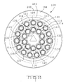
- the connector comprises a circular cross section insulating housing 2 defining a series of nine spaced terminal-receiving cavities 4 arranged in a ring about the axis X-X of the housing 2 as shown in Figures 3 and 4.
- Each cavity 4 which extends axially of the housing 2, opens into a terminal-receiving rear end face 6 and a mating forward end face 8, thereof.
- a circular, cross section hood 10 projects from the housing 2, beyond the mating face 8.
- each cavity 4 is defined by an individual, circular cross section tubular wall 12, formed integrally with a wall 16 in the housing 2, which is perpendicular to the axis X-X.
- the cavity 4 is defined by the outer peripheral wall of the housing 2 and by individual cavity walls 14 also formed integrally with the wall 16.
- the individual walls 12 are interconnected by webs 18 arranged in a ring about the axis X-X.
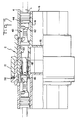
- the walls 12 and 14 cooperate to define an annular stop shoulder 20, shown in Figure 1.
- the hood 10 and the walls 12 cooperate to define an annular guideway 22, within which are axially spaced and opposed guide shoulders 24 and 26, respectively, the latter being annular.
- the interior of each wall 12 is formed with a forwardly facing, annular latching shoulder 25.
- an annular terminal retainer in the form of an axially elongate circular retainer ring 28, for angular displacement about the axis X-X.
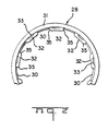
- the ring 28 has a radially inwardly projecting, internal, annular bead 30 which overlies the shoulder 24, and nine constantly peripherally spaced terminal-retaining members 32 which protrude radially inwardly of the retainer ring 28, beyond the lugs 30, each member 32 having a rearwardly opening axial recess 33 and bevelled corners 35 ( Figure 2). Since the end 31 of the retainer ring 28, nearest to the face 6, that is to say its rear end, overlies the shoulder 26 and since the bead 30 overlies the shoulders 24, the retainer ring 28 is held captive in the guideway 22, and is guided thereby in its angular movement about the axis X-X.
- the forward end 37 of the retainer ring 28 is formed with a pair of tool receiving recesses 34.
- the radially outer part of each wall 12 has an arcuate opening 38 by way of which the guideway 22 and the cavity 4 communicate.
- each terminal-retaining member 32 lies between a pair of adjacent walls 12 and thus beyond the openings 38 therein.
- each member 32 is received in a respective opening 38, as shown in Figures 1 and 3, the retainer 28 then being in a terminal-locking, second angular position.
- Electrical terminals 40 each for reception in one of the cavities 4, each comprises a crimping ferrule portion 42 at one end, which has been crimped to the stripped electrically conductive core C of an insulated electrical lead L and also about a corrugated sealing grommet 44 which surrounds the insulation of the lead L.
- the terminal 40 is formed with a mating portion 46, in this example in the form of a plug for mating with an electrical receptacle (not shown).
- each terminal 40 has a transition portion 48 from which opposed, resilient, latching tongues 50 have been struck and which terminates adjacent to the ferrule portion 42, in the radially projecting, circular, abutment collar 52.
- the retainer ring 28 is placed in its first angular ( Figure 4) by inserting prongs of a suitable tool (not shown) through the hood 10 and into the recesses 34 and then rotating the tool to adjust the ring 28 into said first position.
- a terminal 40 is then inserted into each of the cavities 4, by way of the terminal-receiving face 6, with the mating portion 46 leading, until the collar 52 abuts the shoulder 20 preventing further insertion of the terminal 40.
- each terminal 40 latch behind the shoulder 25 in the cavity 4 so that the terminal 40 is retained in its cavity 4, although in the absence of the terminal locking means described herein, it could back out from its cavity 4, when the connector is in use, under the action of vibration, or tensioning of the lead L.
- Each inserted terminal is latched in its cavity, by the tongues 50, whilst the housing 2 is manipulated during the insertion of the remaining terminals 40 into their cavities 4.
- the mating portion 46 thereof projects beyond the mating face 8, into the hood 10, the collar 52 projects into the opening 38, and the grommet 44 engages in sealing tight fashion with the wall of the cavity 4, proximate to the face 6.
- the terminal retainer ring 28 is displaced by means of the tool, from its first angular ( Figure 4) position into its terminal locking, second position ( Figures 1 and 3), whereby each terminal locking member 32 enters the respective opening 38, guided by its bevelled corners 35, so as to overlie the collar 52 of the respective terminal 40 whereby the terminal 40 is prevented from backing out of its cavity 4.
- the recesses 33 in the retaining members 32 allow for tolerances in the dimensions of the collars 52.
- An interfacial seal 54 is positioned on the front shoulder of the mating connector for engagement with the lip 11.
- the connector 2 can accordingly be mated with a sealed socket connector (not shown) so that the assembly so formed is sealed against the ingress of moisture thereinto.
- an electrical socket connector housing 102 comprises for assembly thereto, a terminal retainer 104 and a connecting ring 106.
- Figure 6 also shows, for mating with the housing 102, an electrical pin connector housing 108 comprising for assembly thereto, a terminal retainer 110 identical with the terminal retainer 104, and panel mounting ring 112.
- Each of the parts shown in Figure 6 was molded in one piece from an insulating material and is of overall circular cross-section.
- housing 108 which are similar to, or are identical with, corresponding parts of the housing 102 will now be described.
- the corresponding parts of the housing 102 are similarly referenced to those of the housing 108 but with the addition of a prime symbol.
- the housing 108 defines a series of ten spaced, terminal receiving through cavities 114 arranged in an inner ring concentric with the axis X-X of the housing 108 as best seen in Figures 11 and 12 and each opening into a terminal receiving rear face 116 of the housing 108 and a mating front face 118 thereof.
- the housing 108 also defines a series of fifteen spaced terminal receiving through cavities 120 arranged in a second and outer ring, concentric with the axis X-X and with the ring of cavities 114, each cavity 120 also opening into the faces 116 and 118. Between the cavities 114 and 120, blind holes 122 of various shapes and sizes were formed the faces 116 and 118 during the molding of the housing 108 to provide relief for warpage of the material from which the housing was molded as the material cooled after the molding operation.
- the housing 108 defines an annular recess 124 concentric with, and disposed between, the two rows of cavities 114 and 120 for receiving the terminal retainer 110.
- the recess 124 communicates with an annular opening 126 in an annular wall 128 which separates the cavities 114 from the cavities 120. The opening 126 thus places the cavities 114 and 120 in communication by way thereof.
- Each cavity 114 and 120 has a larger cross-section part 130 for receiving a crimping ferrule 132 crimped to a lead L, and a sealing grommet 134, of an electrical terminal 136 and a smaller cross-section part 138 for receiving a mounting portion 140 of the terminal 136, from which extends a mating portion 142 in the form of an electrical pin, as shown in Figures 15 and 16.
- the part 130 of each cavity opens into the terminal receiving face 116, the part 138, opening into the mating face 118.
- an annular shoulder 144 for engagement by a resilient latching tongue 146 struck from the mounting portion 140 of the respective terminal 136.
- a shoulder 139 for engagement by an abutment flange 137 surrounding the mounting portion 140 of the terminal 136.
- Each terminal retainer 104 and 110 comprises an annular body 148 in the form of an open ended, circular cross-section tube having a leading end 150 and a trailing end 152 and having peripheral through slots 153 to enhance the resilience of the body 148.
- the trailing end 152 is formed with a pair of opposed slots 154, both of which are seen in Figure 14, for receiving a tool blade (not shown).
- the terminal retainer is formed with a ring of ten radially inwardly directed terminal retaining members 156 extending about the internal periphery of the body 148, and near its trailing end 152, with a pair of opposed, radially inwardly directed, teeth 158 each having, as best seen in Figures 13a and 14a, an inclined cam surface 160 on one side and a radially extending shoulder 162 on its opposite side.
- the inner wall 163 of the recess 124 is formed with a pair of diametrically opposed resilient spurs 164 each for cooperation with a respective tooth 158 as described below.
- each body 148 proximate to its leading end 150, each body 148 has a ring of fifteen outwardly directed terminal retaining members 166, opposite to the terminal retaining members 156.
- the housings 102 and 108 are similar and those parts thereof which are dissimilar to one another will now be described, firstly in respect of the pin housing 108.
- the forward external peripheral wall 168 of the housing 108 is surrounded by a hood 170 which projects forwardly of the mating face 118 and is formed with an external triple screw thread 172 terminating in an offset portion 174.
- the hood 170 has a frusto-conical forward edge 175.
- a triangular cross-section plug 171 also projects forwardly from the mating face 118.
- the rearward external periphery 176 of the housing 108 Adjacent to the screw thread 172, the rearward external periphery 176 of the housing 108 is formed with three threads 178 following each other about the periphery 176, and each having an entry end 180 having an open side 182 adjoining the screw thread 172.
- the floor of each thread 178 Proximate to end 184 of each thread 178, opposite to its entry end 180, the floor of each thread 178 is formed with a ramp 186 which is inclined outwardly of the thread 178 in the direction of its end 184. Between the end 184 and the ramp 186, ramp 186 merges with further ramp 188, at an apex 190, the ramp 188 being inclined inwardly of the thread 178, the thread 178 deepening abruptly, between the ramp 188 and the end 184.
- the outer peripheral wall 176 of the housing 108 is formed with a panel mounting flange 196 which extends about the whole periphery of the wall 176.
- the wall 176 is formed with stop 198 parallel with the flange 196 but extending only about a short portion of the periphery of the wall 176 as best seen in Figures 13 and 14.
- Guide grooves 199 are formed in the wall 176 between an annular groove 197 therein and the threads 178, and follow one another about the periphery of the wall 176.
- the flange 196 is surmounted by three constantly spaced indicator pips 200, the purpose of which is explained below.
- a skirt 202 there projects from the terminal receiving face 116, a skirt 202, the outer periphery of which is formed with finger grips 204.
- the internal wall of the hood 170 is formed with keys 206 of different cross sectional shapes distributed about its periphery, and which extend into grooves 208 in the peripheral wall 168, these being shown in Figures 13 and 14.
- the panel mounting ring 112 has a leading end 208 and a trailing end 210. It is formed at its end 210 with series of internally projecting guide ribs 212 distributed about the internal periphery of the ring 112, each for reception in a respective guide groove 199 in the wall 176 of the housing 108. Each thread 216 has a central transverse groove 217.
- the internal periphery of the ring 112 is also formed, intermediate the ends 208 and 210, with three radially inwardly projecting threads 216 which are inclined with respect to the axis of the ring 112, each for reception in a respective thread 178 of the housing 108.
- the ring 112 is formed with a series of internally projecting flanges 218 for engagement with the outer surfaces of the forward walls of the threads 178. Proximate to its leading end 208 the ring 112 has an external, outwardly projecting, panel engaging, peripheral rim 220 and external finger grips 222 between the rim 220 and the end 210.
- the ring 112 is assembled to the housing 108 with its end 208 leading, to position each thread 216 in a corresponding thread 178, whereafter the ring 112 is rotated, until the central groove 217 of each rib 216 snaps into engagement with the apex 190 in the corresponding thread 178 and each rib 212 engages in a respective groove 199.
- the flanges 218 engage against said forward walls of the threads 178, the rim 220 engaging the flange 198.
- the ring 112 is thereby fixed to the housing 108.
- the housing 108 In order to secure the housing 108 to a panel (not shown), the housing 108 is inserted through a circular hole in the panel, with the hood 170 leading, until the flange 196 butts against the margin of the hole.
- the ring 112 is then mounted to the housing 108 as described above so that the margin of the panel is trapped between flange 196 and the rim 220 of the ring 112.
- the snap engagement of the apices 190 in the grooves 217 indicates audibly that the ring 112 has properly been secured to the housing 108.
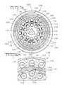
- the terminal retainer 100 is mounted to the housing 108 by inserting it with its end 150 leading, into the recess 124 so that the terminal retaining members 156 and 166 lie in the opening 126 which, as mentioned above, intersects all of the cavities 114 and 120, with each spur 164 engaging the cam surface side 160 of a respective tooth 158 as best seen in Figure 13a.
- the terminal retaining members 156 lie between the cavities 114 of the inner ring of cavities
- the terminal retaining members 166 lie between the cavities 120 of the outer ring of cavities.
- a terminal 136 can be inserted into each cavity 114 and 120 as shown in Figure 15 with the crimping ferrule 132 and the sealing grommet 134 of the terminal in the part 130 of the cavity, the abutment flange 137 engaging the shoulder 139 in the cavity and the latching tongue 146 of the terminal engaged with the shoulder 144 so that the terminal is latched in position in the cavity, although it could back out therefrom against the action of the tongue 146, which is not very robust, for example under the influence of vibration, or if the lead L to which the ferrule 136 is crimped, should be unduly tensioned.
- the terminal retainer 110 is then rotated by means of a tool blade engaged in the notches 154, in a clockwise sense, as seen in Figures 13 and 13a so that each tooth 158 on the terminal retainer 10 rides over the respective spur 164, assisted by the cam surface 160 of the tooth 158, to lodge against the shoulder 162 on the other side of the tooth 158 as best seen in Figure 14a.
- the terminal retainer 10 is then in its terminal locking position, in which as best seen in Figures 14a and 16, the terminal retaining members 156 intersect the cavities 114 and the terminal retaining members 166 intersect the cavities 120; so that the members 156 overlie the abutment flanges 137 of the terminals in the cavities 114 and the members 166 overlie the abutment flanges 137 of the terminals in the cavities 120.
- Each terminal is accordingly locked in its cavity between the shoulder 139 therein and respective terminal retaining member so that it cannot back out from its cavity under any circumstances.
- the housing 102 will now be described in so far as it differs from the housing 108.
- the cavities 114′ and 120′ of the housing 102 are dimensioned to receive terminals 136′ (one of which is shown in Figure 8) which differ from the terminals 136 in that instead of having mating portions in the form of electrical pins they have mating portions 240 in the form of sockets for the pins 142.
- the remaining parts of the terminals 136′ are substantially identical to those of the terminals 136.
- the free ends of the sockets 240 are substantially flush with the mating face 118′ of the housing 102.
- a hood 242 formed with external keyways 244, best seen in Figure 10, each dimensioned to receive a respective key 206 in the hood 170 of the housing 108.
- These keyways 244 also extend peripherally over the wall 168′ of the housing 102.
- a skirt 246 projects from the terminal receiving face 116′ of the housing 102, a skirt 246 and there extends from the wall 168′, a latching ring 248 surrounding the wall 168′ and defining in cooperation therewith an annular socket 250, as best seen in Figure 8.
- the socket 250 has an inner part 249 receiving a sealing ring 251 and which terminates in a reduced cross-section, frusto-conical cross-section, annular recess 253.
- the ring 248 is formed with latch arms 252 distributed about its external periphery and having free ends directed towards the face 116′, that is to say rearwardly of the housing 102. Between each adjacent pair of latch arms 252 is an axial rib 254. The ring 248 is formed with an external peripheral groove 256. There projects forwardly from the face 118′ of the housing 102 a triangular cross-section receptacle 258 for mating with the triangular cross-section plug 171 of the housing 108.
- the coupling ring 106 has a leading end 260 and a trailing end 262.
- the ring 106 is formed with three radially inwardly projecting studs 264 (only one of which is shown in Figure 6) for meshing with the thread 172 of the housing 108, and between each pair of adjacent studs 264, with two circumferentially spaced ribs 266 extending axially of the ring 106.
- the ring 106 is formed with a series of internally projecting circumferential ribs 268. The external periphery of the ring 106 is provided with finger grips 270.
- each of three constantly spaced ribs 270 is an axially extending indicator arrow 272 for co-operation with a pip 200 on the flange 196 of the housing 108, as described below.
- the ring 106 is assembled to the housing 102, with its end 260 leading so that the ribs 268 depress the latch arms 252 on the ring 248 of the housing 102, and pass over them so that the ribs 268 slidably engage in the groove 256 of the ring 248, the arms 252 resiling thereafter, so that the ring 106 is secured to the ring 102, being freely rotatable thereabout.
- Ring 106 is prevented from backing off from the ring 102 by engagement of the free end of the ring 248 with the studs 264 and ribs 266.
- the terminal retainer 104 is assembled to the housing 202 in the manner described above with reference to the terminal retainer 110 and the housing 108 so that the terminal retainer 104 is in its terminal insertion angular position when so assembled.
- the terminals 136′ are inserted into the cavities 114′, 120′ of the housing 102 to be latched therein by means of their latching lances 246′ and the terminals 136 are inserted into the cavities 114 and 120 of the housing 108 similarly to be latched therein.
- the housing 108 is then inserted into the circular hole in the panel with its hood 170 leading, and the ring 112 is assembled to the housing 108 to secure it firmly to the panel in the manner described above.
- the terminal retainers 104 and 110 are then rotated to their terminal locking angular positions by means of the tool mentioned above so that the terminals cannot back out from their cavities, as described above.
- the keys 206 of the hood 170 are slidably engaged with the respective keyways 244 of the hood 242, so that the hood 242 is received in the hood 170 and the coupling ring 106 is rotated so that the studs 264 thereof mesh with the screw threads 172 of the hood 170 whereby the housings are drawn together so that the ring 112 is received in the ring 106 with the frusto-conical edge 175 of hood 170 extending into the annular socket 250 defined between the ring 248 and the wall 168′ of the housing 102 and the leading side of the flange 220 engaging the end 262 of the ring 106.
- Said edge 175 compresses the sealing ring 251 so that it fills the recess 253, thereby enhancing the sealing between the housings 102 and 108.
- each of the studs 264 engage with a snap action in the offset portion 174 of the respective thread 172, thereby indicating audibly that the housings 102 and 108 have been fully mated so that each pin 142 is properly received in a respective socket 240.
- the fully mated condition of the housings is also indicated by coincidence between each pip 200 on the flange 196 of the housing 108 and a respective arrow 272 on the coupling ring 106. Where the panel is of small extent, being for example an angle bracket in a motor vehicle, the pips 200 and the arrows 272 will be readily visible.
- the outer peripheral walls thereof are free to receive the various means for coupling the two housings in the manner described above, that the housings may have two rings of terminal receiving cavities and that external sealing rings may be used with the housings.
Landscapes
- Connector Housings Or Holding Contact Members (AREA)
- Details Of Connecting Devices For Male And Female Coupling (AREA)
Applications Claiming Priority (4)
| Application Number | Priority Date | Filing Date | Title |
|---|---|---|---|
| GB8817402 | 1988-07-21 | ||
| GB888817402A GB8817402D0 (en) | 1988-07-21 | 1988-07-21 | Electrical connector housing & electrical connector |
| GB898906956A GB8906956D0 (en) | 1989-03-28 | 1989-03-28 | Electrical connector housing |
| GB8906956 | 1989-03-28 |
Publications (2)
| Publication Number | Publication Date |
|---|---|
| EP0352087A1 true EP0352087A1 (fr) | 1990-01-24 |
| EP0352087B1 EP0352087B1 (fr) | 1994-04-20 |
Family
ID=26294189
Family Applications (1)
| Application Number | Title | Priority Date | Filing Date |
|---|---|---|---|
| EP89307307A Expired - Lifetime EP0352087B1 (fr) | 1988-07-21 | 1989-07-19 | Connecteur électrique |
Country Status (9)
| Country | Link |
|---|---|
| US (1) | US4936798A (fr) |
| EP (1) | EP0352087B1 (fr) |
| JP (1) | JP2823888B2 (fr) |
| KR (1) | KR940009369B1 (fr) |
| AR (1) | AR242317A1 (fr) |
| BR (1) | BR8903602A (fr) |
| DE (1) | DE68914739T2 (fr) |
| ES (1) | ES2051368T3 (fr) |
| PT (1) | PT91244B (fr) |
Cited By (4)
| Publication number | Priority date | Publication date | Assignee | Title |
|---|---|---|---|---|
| FR2729794A1 (fr) * | 1995-01-19 | 1996-07-26 | Cinch Connecteurs Sa | Connecteur electrique |
| DE4439386C5 (de) * | 1994-11-04 | 2005-10-06 | Delphi Automotive Systems Deutschland Gmbh | Elektrischer Verbindungsteil einer zweiteiligen Steckverbindung |
| EP1926179A3 (fr) * | 2006-11-24 | 2009-04-29 | Harting Electric GmbH & Co. KG | Connecteur à fiches pour conducteurs électriques assemblés |
| CN107146980A (zh) * | 2017-06-16 | 2017-09-08 | 山东优安新能源汽车零部件有限公司 | 一种电动汽车插针密封垫 |
Families Citing this family (12)
| Publication number | Priority date | Publication date | Assignee | Title |
|---|---|---|---|---|
| JPS6419272U (fr) * | 1987-07-24 | 1989-01-31 | ||
| US5135416A (en) * | 1989-09-06 | 1992-08-04 | Amp Incorporated | Electrical connector housing |
| FR2673050B1 (fr) * | 1991-02-15 | 1994-01-28 | Francelco | Bloc de connexion electrique enfichable et connecteur incorporant un tel bloc. |
| US5533157A (en) * | 1992-11-02 | 1996-07-02 | Itt Corporation | Optical fiber connector biasing arrangement |
| DE4330359C2 (de) * | 1993-09-08 | 1995-06-14 | Reinshagen Kabelwerk Gmbh | Gedichteter elektrischer Steckverbinder |
| GB9413305D0 (en) * | 1994-07-01 | 1994-08-24 | Amp Gmbh | Connector housing having secondary locking feature |
| US5716233A (en) * | 1995-11-30 | 1998-02-10 | Itt Corporation | Contact position assurance device |
| US5730624A (en) * | 1995-11-30 | 1998-03-24 | Itt Corporation | Secondary contact lock arrangement |
| JPH10302880A (ja) * | 1997-04-25 | 1998-11-13 | Jatco Corp | 防水コネクタ構造 |
| SE9903800L (sv) * | 1999-10-21 | 2001-04-22 | Kim Silfverberg | Kabelkopplingsanordning |
| RU2455203C1 (ru) * | 2011-01-19 | 2012-07-10 | Федеральное государственное унитарное предприятие "Государственный космический научно-производственный центр имени М.В. Хруничева" | Электросоединитель |
| KR102569694B1 (ko) * | 2021-05-12 | 2023-08-23 | 파이룽 머시너리 밀 코., 엘티디. | 직물의 피복 표면 상태를 바탕으로 즉시 편직기 상태를 알리기 위한 원형 편 직기 |
Citations (3)
| Publication number | Priority date | Publication date | Assignee | Title |
|---|---|---|---|---|
| FR1539296A (fr) * | 1966-09-26 | 1968-09-13 | Int Standard Electric Corp | Perfectionnements aux connecteurs électriques |
| FR2389250A1 (fr) * | 1977-04-25 | 1978-11-24 | Labinal | Clip de contact electrique cylindrique |
| EP0025366A1 (fr) * | 1979-08-31 | 1981-03-18 | The Bendix Corporation | Connecteur électrique séparable du type contenant des premiers et seconds membres connecteurs avec des contacts améliorés pour l'un des membres connecteurs |
Family Cites Families (6)
| Publication number | Priority date | Publication date | Assignee | Title |
|---|---|---|---|---|
| GB533310A (en) * | 1939-08-10 | 1941-02-11 | Rotax Ltd | Improvements relating to plug and socket electrical couplings |
| US3404364A (en) | 1966-07-19 | 1968-10-01 | Amp Inc | Electrical connector |
| US3573720A (en) * | 1969-01-07 | 1971-04-06 | Amp Inc | Electrical connector |
| US4113333A (en) * | 1977-05-23 | 1978-09-12 | Sloan Valve Company | Electrical connector receptacle |
| DE8508465U1 (de) * | 1985-03-21 | 1986-01-09 | Amp Deutschland Gmbh, 6070 Langen | Verbinder mit einem drehbaren Einsatz zum Festhalten von Anschlüssen |
| US4653839A (en) * | 1985-06-24 | 1987-03-31 | Itt Corporation | Connector with removable socket elements |
-
1989
- 1989-07-17 US US07/381,225 patent/US4936798A/en not_active Expired - Lifetime
- 1989-07-19 KR KR1019890010196A patent/KR940009369B1/ko not_active Expired - Fee Related
- 1989-07-19 ES ES89307307T patent/ES2051368T3/es not_active Expired - Lifetime
- 1989-07-19 DE DE68914739T patent/DE68914739T2/de not_active Expired - Lifetime
- 1989-07-19 EP EP89307307A patent/EP0352087B1/fr not_active Expired - Lifetime
- 1989-07-20 AR AR89314459A patent/AR242317A1/es active
- 1989-07-20 BR BR898903602A patent/BR8903602A/pt not_active IP Right Cessation
- 1989-07-21 JP JP1190412A patent/JP2823888B2/ja not_active Expired - Lifetime
- 1989-07-21 PT PT91244A patent/PT91244B/pt not_active IP Right Cessation
Patent Citations (3)
| Publication number | Priority date | Publication date | Assignee | Title |
|---|---|---|---|---|
| FR1539296A (fr) * | 1966-09-26 | 1968-09-13 | Int Standard Electric Corp | Perfectionnements aux connecteurs électriques |
| FR2389250A1 (fr) * | 1977-04-25 | 1978-11-24 | Labinal | Clip de contact electrique cylindrique |
| EP0025366A1 (fr) * | 1979-08-31 | 1981-03-18 | The Bendix Corporation | Connecteur électrique séparable du type contenant des premiers et seconds membres connecteurs avec des contacts améliorés pour l'un des membres connecteurs |
Cited By (4)
| Publication number | Priority date | Publication date | Assignee | Title |
|---|---|---|---|---|
| DE4439386C5 (de) * | 1994-11-04 | 2005-10-06 | Delphi Automotive Systems Deutschland Gmbh | Elektrischer Verbindungsteil einer zweiteiligen Steckverbindung |
| FR2729794A1 (fr) * | 1995-01-19 | 1996-07-26 | Cinch Connecteurs Sa | Connecteur electrique |
| EP1926179A3 (fr) * | 2006-11-24 | 2009-04-29 | Harting Electric GmbH & Co. KG | Connecteur à fiches pour conducteurs électriques assemblés |
| CN107146980A (zh) * | 2017-06-16 | 2017-09-08 | 山东优安新能源汽车零部件有限公司 | 一种电动汽车插针密封垫 |
Also Published As
| Publication number | Publication date |
|---|---|
| BR8903602A (pt) | 1990-03-20 |
| KR900002499A (ko) | 1990-02-28 |
| DE68914739D1 (de) | 1994-05-26 |
| JPH0275175A (ja) | 1990-03-14 |
| ES2051368T3 (es) | 1994-06-16 |
| JP2823888B2 (ja) | 1998-11-11 |
| PT91244A (pt) | 1990-02-08 |
| DE68914739T2 (de) | 1994-11-24 |
| AR242317A1 (es) | 1993-03-31 |
| US4936798A (en) | 1990-06-26 |
| KR940009369B1 (ko) | 1994-10-07 |
| PT91244B (pt) | 1995-07-03 |
| EP0352087B1 (fr) | 1994-04-20 |
Similar Documents
| Publication | Publication Date | Title |
|---|---|---|
| EP0352087B1 (fr) | Connecteur électrique | |
| EP0932918B1 (fr) | Connecteur electrique etanche | |
| US4921437A (en) | Sealed electrical connector assembly with terminal retainer | |
| EP0425130B1 (fr) | Connecteur électrique avec fermeture supplémentaire articulée | |
| US6361348B1 (en) | Right angle, snap on coaxial electrical connector | |
| US4497531A (en) | Electrical connector | |
| US4214802A (en) | Waterproof electric connector | |
| EP0599165B1 (fr) | Connecteur électrique avec système d'alignement et d'arrêt en position pour éléments de contact | |
| US7147513B2 (en) | Shielded connector with insert molded shielding shell and resin cover | |
| EP2346120B1 (fr) | Connecteur blindé et son procédé de production | |
| US6059594A (en) | Sealed electrical connector | |
| US6257918B1 (en) | Wire harness connector having a contact retention plate | |
| US4479691A (en) | Connector assembly | |
| JPH07118346B2 (ja) | 密封型電気コネクタ | |
| US20030032321A1 (en) | Sealed connector | |
| EP0270270B1 (fr) | Assemblage de boîtier de connecteur électrique | |
| US6179657B1 (en) | Waterproof connector and method of assembling the same | |
| US6783396B1 (en) | Airtight plug connector and terminal insert | |
| US5158474A (en) | Keying for a shielded electrical connector | |
| US6722922B2 (en) | Heavy duty electrical connector | |
| US5219301A (en) | Keying for a shielded electrical connector | |
| US20010012717A1 (en) | Connector | |
| US5009615A (en) | Terminal assembly with fixed and flexible tab receptacle retainers | |
| JPH09199219A (ja) | 防水コネクタ及びこれに使用される盲栓 | |
| JPH06181078A (ja) | コネクタの連結構造 |
Legal Events
| Date | Code | Title | Description |
|---|---|---|---|
| PUAI | Public reference made under article 153(3) epc to a published international application that has entered the european phase |
Free format text: ORIGINAL CODE: 0009012 |
|
| AK | Designated contracting states |
Kind code of ref document: A1 Designated state(s): DE ES FR GB IT NL SE |
|
| 17P | Request for examination filed |
Effective date: 19900713 |
|
| RAP1 | Party data changed (applicant data changed or rights of an application transferred) |
Owner name: THE WHITAKER CORPORATION |
|
| 17Q | First examination report despatched |
Effective date: 19930324 |
|
| GRAA | (expected) grant |
Free format text: ORIGINAL CODE: 0009210 |
|
| AK | Designated contracting states |
Kind code of ref document: B1 Designated state(s): DE ES FR GB IT NL SE |
|
| REF | Corresponds to: |
Ref document number: 68914739 Country of ref document: DE Date of ref document: 19940526 |
|
| REG | Reference to a national code |
Ref country code: ES Ref legal event code: FG2A Ref document number: 2051368 Country of ref document: ES Kind code of ref document: T3 |
|
| ET | Fr: translation filed | ||
| ITF | It: translation for a ep patent filed | ||
| EAL | Se: european patent in force in sweden |
Ref document number: 89307307.2 |
|
| PLBE | No opposition filed within time limit |
Free format text: ORIGINAL CODE: 0009261 |
|
| STAA | Information on the status of an ep patent application or granted ep patent |
Free format text: STATUS: NO OPPOSITION FILED WITHIN TIME LIMIT |
|
| 26N | No opposition filed | ||
| REG | Reference to a national code |
Ref country code: GB Ref legal event code: IF02 |
|
| PGFP | Annual fee paid to national office [announced via postgrant information from national office to epo] |
Ref country code: GB Payment date: 20040615 Year of fee payment: 16 |
|
| PGFP | Annual fee paid to national office [announced via postgrant information from national office to epo] |
Ref country code: NL Payment date: 20040621 Year of fee payment: 16 |
|
| PGFP | Annual fee paid to national office [announced via postgrant information from national office to epo] |
Ref country code: FR Payment date: 20040702 Year of fee payment: 16 |
|
| PGFP | Annual fee paid to national office [announced via postgrant information from national office to epo] |
Ref country code: SE Payment date: 20040705 Year of fee payment: 16 |
|
| PGFP | Annual fee paid to national office [announced via postgrant information from national office to epo] |
Ref country code: ES Payment date: 20040720 Year of fee payment: 16 |
|
| PG25 | Lapsed in a contracting state [announced via postgrant information from national office to epo] |
Ref country code: IT Free format text: LAPSE BECAUSE OF NON-PAYMENT OF DUE FEES;WARNING: LAPSES OF ITALIAN PATENTS WITH EFFECTIVE DATE BEFORE 2007 MAY HAVE OCCURRED AT ANY TIME BEFORE 2007. THE CORRECT EFFECTIVE DATE MAY BE DIFFERENT FROM THE ONE RECORDED. Effective date: 20050719 Ref country code: GB Free format text: LAPSE BECAUSE OF NON-PAYMENT OF DUE FEES Effective date: 20050719 |
|
| PG25 | Lapsed in a contracting state [announced via postgrant information from national office to epo] |
Ref country code: SE Free format text: LAPSE BECAUSE OF NON-PAYMENT OF DUE FEES Effective date: 20050720 Ref country code: ES Free format text: LAPSE BECAUSE OF NON-PAYMENT OF DUE FEES Effective date: 20050720 |
|
| PG25 | Lapsed in a contracting state [announced via postgrant information from national office to epo] |
Ref country code: NL Free format text: LAPSE BECAUSE OF NON-PAYMENT OF DUE FEES Effective date: 20060201 |
|
| EUG | Se: european patent has lapsed | ||
| GBPC | Gb: european patent ceased through non-payment of renewal fee |
Effective date: 20050719 |
|
| PG25 | Lapsed in a contracting state [announced via postgrant information from national office to epo] |
Ref country code: FR Free format text: LAPSE BECAUSE OF NON-PAYMENT OF DUE FEES Effective date: 20060331 |
|
| NLV4 | Nl: lapsed or anulled due to non-payment of the annual fee |
Effective date: 20060201 |
|
| REG | Reference to a national code |
Ref country code: FR Ref legal event code: ST Effective date: 20060331 |
|
| REG | Reference to a national code |
Ref country code: ES Ref legal event code: FD2A Effective date: 20050720 |
|
| PGFP | Annual fee paid to national office [announced via postgrant information from national office to epo] |
Ref country code: DE Payment date: 20080829 Year of fee payment: 20 |