EP0352088B1 - Connecteur électrique - Google Patents
Connecteur électrique Download PDFInfo
- Publication number
- EP0352088B1 EP0352088B1 EP89307308A EP89307308A EP0352088B1 EP 0352088 B1 EP0352088 B1 EP 0352088B1 EP 89307308 A EP89307308 A EP 89307308A EP 89307308 A EP89307308 A EP 89307308A EP 0352088 B1 EP0352088 B1 EP 0352088B1
- Authority
- EP
- European Patent Office
- Prior art keywords
- socket
- terminal
- spring sleeve
- helper
- sleeve
- Prior art date
- Legal status (The legal status is an assumption and is not a legal conclusion. Google has not performed a legal analysis and makes no representation as to the accuracy of the status listed.)
- Expired - Lifetime
Links
Images


Classifications
-
- H—ELECTRICITY
- H01—ELECTRIC ELEMENTS
- H01R—ELECTRICALLY-CONDUCTIVE CONNECTIONS; STRUCTURAL ASSOCIATIONS OF A PLURALITY OF MUTUALLY-INSULATED ELECTRICAL CONNECTING ELEMENTS; COUPLING DEVICES; CURRENT COLLECTORS
- H01R13/00—Details of coupling devices of the kinds covered by groups H01R12/70 or H01R24/00 - H01R33/00
- H01R13/02—Contact members
- H01R13/15—Pins, blades or sockets having separate spring member for producing or increasing contact pressure
- H01R13/18—Pins, blades or sockets having separate spring member for producing or increasing contact pressure with the spring member surrounding the socket
-
- H—ELECTRICITY
- H01—ELECTRIC ELEMENTS
- H01R—ELECTRICALLY-CONDUCTIVE CONNECTIONS; STRUCTURAL ASSOCIATIONS OF A PLURALITY OF MUTUALLY-INSULATED ELECTRICAL CONNECTING ELEMENTS; COUPLING DEVICES; CURRENT COLLECTORS
- H01R13/00—Details of coupling devices of the kinds covered by groups H01R12/70 or H01R24/00 - H01R33/00
- H01R13/40—Securing contact members in or to a base or case; Insulating of contact members
- H01R13/42—Securing in a demountable manner
- H01R13/436—Securing a plurality of contact members by one locking piece or operation
- H01R13/4361—Insertion of locking piece perpendicular to direction of contact insertion
Definitions
- the invention is directed to an electrical terminal which has a secondary locking feature provided thereon.
- the terminal has a helper spring sleeve which cooperates therewith, the helper spring sleeve providing the positive secondary locking feature required in many instances.
- German Utility Model Number 36 29 740 One such terminal is disclosed in German Utility Model Number 36 29 740.
- a terminal is provided with a sleeve which extends about the circumference of the terminal.
- the sleeve provides support to resilient arms of the terminal and also provides the secondary locking characteristics required.
- the shoulder of the terminal cooperates with the sleeve to insure that the sleeve is maintained in the proper position relative to the longitudinal axis of the terminal.
- the shoulder is formed from the material which comprises the terminal. In order to provide the required configuration, the shoulder must be coined. These forming and coining operations can result in the failure of the material at the shoulder. In particular, cracks may develop on the surfaces of the shoulders. This is an unacceptable result which causes the failure of an electrical terminal.
- Another problem with the stamping and forming operation described is a result of minimal working space. Due to the lack of space available to perform the coining operation, the coining operation can be very time consuming and difficult, thereby resulting in the cost of manufacture of the
- Another problem associated with stamping and forming the shoulders from the terminal relates to the fact that the terminals are not as accurately positioned in the terminal receiving cavities of the connector.
- the configuration of the shoulder does not allow the shoulder to act as centering means. In other words, due to tolerances, the shoulder must be smaller in diameter than the cavity. When a force is applied to the terminal, the terminal will be allowed to float in the cavity, resulting in an ineffective electrical connection.
- the present invention consists in an electrical terminal as defined in claim 1.
- the present invention consists in an electrical terminal as defined in claim 5.
- a terminal comprises an elongate, tubular socket 2 from which extends a crimping ferrule 4.
- a secondary locking, resilient sleeve 6 is provided in surrounding relationship to socket 2.
- the socket 2 and ferrule 4 are stamped and formed from a single piece of sheet metal stock, as is the sleeve 6.
- the socket has a longitudinal seam 7 which extends over its entire length.
- the socket is formed with a plurality of slots 8 provided in the sidewalls thereof.
- the slots 8 are essentially parallel to each other, with each slot being at an angle relative to the longitudinal seam 7 of the socket 2.
- arms of metal which form contact spring arms 10.
- the number of contact springs 10 can vary in number according to the particular contact force required for operation. In the embodiment shown, eight contact spring arms are provided.
- Each contact spring arm 10 has a contact boss 12 projecting into a pin receiving passage 14, the pin receiving passage being best shown in Figures 1 and 3.
- the pin receiving passage 14 is defined by the walls of socket 2.
- the bosses 12 are arranged in the same plane, substantially at the longitudinal center of contact spring arms 10. However, if a low insertion socket is required, the bosses 12 can be staggered along the longitudinal axis of the socket, thereby facilitating the insertion of pin 15, Figure 5b, into the socket under reduced insertion force conditions.
- Passage 14 has a pin receiving end 16 which is defined by a continuous circumferential ring portion which extends about socket 2.
- the diameter of the pin receiving end 16 is greater than the diameter of socket 2 at the position where bosses 12 are located. This allows pin receiving end 16 to act as a lead-in surface.
- a stop plate 18 is provided in passage 14 at an end opposite pin receiving end 16. Stop plate 18 cooperates with pin 15 such that as pin 15 is inserted into socket 2, the pin is prevented from overinsertion.
- sleeve 6 is stamped from a single sheet of rolled metal 21. After stamping sleeve 6 is formed into a pre-assembly position. In this pre-assembly position, the sleeve 6 is open, such that the sleeve is in a substantially U-shaped configuration, as shown in Figure 1.
- An edge 24 of sleeve 6 has a pair of identical uniplanar ears 28, the ears project in opposite senses from a stem 29 which in turn projects from the edge 24.
- An opposite edge 26 of sleeve 6 has an aperture 30 for receiving the ears 28 therein when sleeve 6 is fully assembled to socket 2.
- Each opening 30 has a wide portion 32 dimensioned to receive ears 28 therein and a narrower portion 34 adjacent to wide portion 32.
- the keyhole configuration allows ears 28 to be easily inserted into side portion 32 of aperture 30. Stem 29 is then moved into narrow portion 34, such that ears 28 cooperate with the shoulders to latch sleeve 6 onto socket 2, as shown in Figure 4.
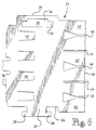
- sleeve 6 has a first end 36 and a second end 38. Proximate first end 36 are resilient securing arms 40. Securing arms 40 are stamped and formed from the sidewalls of sleeve 6. Provided adjacent second end 38 are resilient locking spring arms 42. Locking spring arms 42 are also stamped from the sidewalls and are formed so that a mid portion 44 extends outward from the sidewalls. End portions 46 of locking spring arms 42 are positioned to lie in essentially the same plane as the sidewall of sleeve 6, as is best shown in Figures 2 and 5. Locking spring arms 42 are separated from each other by slots 48, 49, as shown in Figure 6. The configuration of slots 48, 49 and projections 42 enhance the resilient characteristics of projections 42, as will be more fully discussed below.
- sleeve 6 In order to assemble the sleeve 6 to the socket 2, sleeve 6 is placed in socket 2, when the sleeve is in the pre-assembly position, as indicated by the arrow in Figure 1. Sleeve 6 is compressed to move the edges 24 and 26 toward each other, so that ears 28 are inserted through wide portion 34 of opening 30. With ears 28 properly seated in wide portion 34 of opening 30, the pressure on the sleeve 6 is relaxed causing edges 24, 26 to move away from each other, forcing ears 28 into narrow portion 34 of opening 30. This cooperation of ears 28 and opening 30 provides a type of latching arrangement, whereby the sleeve 6 is secured to the socket 2 (see Figure 4).
- Sleeves 6 and pins 15 are so relatively dimensioned that when the pins are inserted into the passages 14 of the sockets 2, the pins engage the bosses 12, thereby deflecting the contact spring arms 10 radially outwardly of the sockets 2 until further radial outward deflection of sockets 2 is resiliently constrained by sleeves 6 just prior to pins 15 butting against stop plates 18.
- the resulting hoop stresses ensure that a final high contact force is exerted against each pin 15 by the contact bosses 12.
- the manner in which the sleeves 6 are slipped about the socket 2 as described above leaves clearance between the sockets 2 and the sleeves 6, thereby avoiding damage to sockets 2, during the assembly thereto of sleeves 6. It should also be noted, that the clearance allows for the initial insertion force of pins 15 into sockets 2 to be low.
- each assembled terminal is inserted into a respective terminal receiving cavity 52 of housing 50 through a first major surface 54 of the housing.
- the terminal is fully inserted when projections 20 engage shoulders 56 of housing 50.
- resilient securing arms 40 cooperate with shoulders 58. The cooperation of projections 20 and resilient securing arms 40 with respective shoulders 56, 58 prevents the movement of the terminals along the longitudinal axis of cavities 52.
- portions 59 of cam 60 or second housing are positioned in cavities 52, as shown in Figure 5b.
- the positioning of the cam in the cavity provides a shoulder 62 which cooperates with locking spring arms 42 to provide secondary locking for the terminal.
- Locking spring arms 42 cooperate with the sidewalls of the cavity to insure that the longitudinal axis of the socket coincides with the longitudinal axis of the cavity.
- locking spring arms 42 provides for a strong secondary locking action. As pins 15 are inserted into sockets 2, a force is exerted on the terminals. This force is in the direction of insertion, which causes the terminals to move toward surface 54. As this movement occurs, locking spring arms 42 engage portions 59 of cam 60. This engagement causes locking spring arms 42 to deform in such a manner as to maintain the terminals in the required position both longitudinally of the axis and transversely. As locking spring arms 42 cooperate with portions 59, locking spring arms 42 are forced to pivot. This pivoting motion causes midportions 44 of locking spring arms 42 to move toward respective sidewalls of cavities 52, thereby apply a force to the sidewalls of the cavities.
- This force is equally distributed about the circumference of each of the terminals and prevents the movement of the terminals in a direction which is transverse to the longitudinal axis of the cavity. It should be noted, that the frictional engagement of midportions 44 against the sidewalls also helps to distribute the forces along the sidewalls, thereby alleviating the problem of large forces being applied to portions 59 of cam 60.
- projections 20 and locking spring arms 42 also prevents the rotation of the terminals in the housing. As described above, during the insertion of pins 15 into sockets 2, the locking spring arms 42 are forced into frictional engagement with the sidewall of cavities 52. This frictional engagement prevents the movement of midportions 44 of locking spring arms 42 relative to the sidewalls. Therefore, as projections 20 are positioned and maintained in slots 48 (which are provided between locking spring arms 42), projections 20 are prevented from rotation as pins 15 are inserted into sockets 2.
Landscapes
- Connector Housings Or Holding Contact Members (AREA)
- Details Of Connecting Devices For Male And Female Coupling (AREA)
Claims (9)
- Borne électrique comportant une douille tubulaire allongée (2) présentant un passage (14) de réception de broche et un manchon à ressort auxiliaire (6) entourant la douille (2), le passage (14) de réception de broche s'étendant d'une extrémité d'accouplement (16) de la douille (2) vers une extrémité d'insertion excessive de la douille (2), la douille (2) étant formée de façon à présenter des fentes (8) formant plusieurs ressorts de contact (10), chaque ressort de contact (10) faisant saillie dans le passage (14), le manchon à ressort auxiliaire (6) ayant une première extrémité (36) qui est proche de l'extrémité d'accouplement (16) de la douille (2) et une seconde extrémité (38) qui est proche de l'extrémité d'insertion excessive de la douille (2), la borne étant caractérisée en ce que :
la douille (2) comporte des saillies (20) prévues à proximité de l'extrémité d'insertion excessive, les saillies (20) s'étendant dans une direction qui est essentiellement perpendiculaire à l'axe longitudinal de la douille (2),
le manchon à ressort auxiliaire (6) comporte des bras à ressort (42) qui sont prévus le long de la circonférence du manchon à ressort auxiliaire (6) à proximité de sa seconde extrémité (38), les bras à ressort (42) étant séparés les uns des autres par des fentes (48, 49) qui sont prévues dans le manchon à ressort auxiliaire (6), et chacun des bras à ressort (42) étant formé de manière que le bras à ressort (42) s'étende vers l'extérieur du manchon à ressort auxiliaire (6), jusqu'à une partie médiane (44) espacée de la douille (2), grâce à quoi les saillies (20) de la douille (2) coopèrent avec les fentes (48) prévues entre les bras à ressort (42) du manchon à ressort auxiliaire (6), de manière que les saillies (20) ne puissent tourner par rapport au manchon à ressort auxiliaire (6), ce qui empêche la borne entière de tourner par rapport au manchon à ressort auxiliaire (6). - Borne électrique selon la revendication 1, caractérisée en outre en ce que les bras à ressort (42) ont des extrémités libres (46) qui sont prévues essentiellement dans le même plan que le manchon à ressort auxiliaire (6).
- Borne électrique selon la revendication 2, caractérisée en outre en ce que les bras à ressort (42) sont amenés à pivoter autour d'extrémités fixes lorsqu'une force est appliquée à proximité des extrémités libres (46) des bras à ressort (42), permettant ainsi aux parties médianes (44) de s'éloigner de l'axe longitudinal de la borne.
- Borne électrique selon la revendication 3, caractérisée en outre en ce que, pendant que les bras à ressort (42) sont amenés à pivoter à force, une partie du manchon à ressort auxiliaire (6) qui est proche des extrémités fixes est déplacée à force vers l'axe longitudinal de la borne, de manière que le manchon à ressort auxiliaire (6) porte contre des parois latérales de la douille (2) pour assurer que la borne est maintenue en position par rapport au manchon à ressort auxiliaire (6).
- Borne électrique à utiliser dans un connecteur (50) ayant un boîtier qui présente des cavités de réception de bornes dimensionnées pour recevoir des bornes, la borne comportant une douille tubulaire allongée (2) ayant un passage (14) de réception de broche et un manchon à ressort auxiliaire (6) entourant la douille (2), le passage (14) de réception de broche s'étendant d'une extrémité (16) d'accouplement de la douille (2) vers une extrémité d'insertion excessive de la douille (2), la douille (2) étant formée de façon à présenter des fentes (8) formant plusieurs ressorts de contact (10), chaque ressort de contact (10) faisant saillie dans le passage (14), le manchon à ressort auxiliaire (6) ayant une première extrémité (36) qui est proche de l'extrémité d'accouplement (16) de la douille (2) et une seconde extrémité (38) qui est proche de l'extrémité d'insertion excessive de la douille (2), le manchon à ressort auxiliaire (6) ayant des bras élastiques (40) de verrouillage qui coopèrent avec des parois des cavités (52) de réception de borne pour verrouiller la borne dans le boîtier, la borne étant caractérisée en ce que :
la douille (2) comporte des saillies (20) prévues à proximité de l'extrémité d'insertion excessive, les saillies (20) s'étendant dans une direction qui est essentiellement perpendiculaire à l'axe longitudinal de la douille (2),
le manchon à ressort auxiliaire (6) comporte des bras à ressort (42) qui sont prévus le long de la circonférence du manchon à ressort auxiliaire (6) à proximité de sa seconde extrémité (38), les bras à ressort (42) étant séparés les uns des autres par des fentes (48, 49) qui sont prévues dans le manchon à ressort auxiliaire (6), et chacun des bras à ressort (42) étant formé de manière que le bras à ressort (42) s'étende vers l'extérieur du manchon à ressort auxiliaire (6) jusqu'à une partie médiane (44) espacée de la douille (2), à une plus grande distance que les saillies (20) de la douille (2),
grâce à quoi, lorsqu'une force est appliquée aux extrémités (46) des bras à ressort (42), les bras à ressort (42) sont amenés à pivoter autour d'un point de pivotement, assurant ainsi que le manchon à ressort auxiliaire (6) est convenablement fixé à la douille (2) et grâce à quoi les bras à ressort (42) peuvent coopérer avec des épaulements (59) d'un connecteur (50) pour produire la force demandée pour faire pivoter les bras à ressort (42). - Borne électrique selon la revendication 5, caractérisée en outre en ce que les bras à ressort (42) ont des extrémités libres (46) qui sont prévues essentiellement dans le même plan que le manchon à ressort auxiliaire (6).
- Borne électrique selon la revendication 6, caractérisée en outre en ce que les bras à ressort (42) sont amenés à pivoter autour d'extrémités fixes lorsqu'une force est appliquée à proximité des extrémités libres (46) des bras à ressort (42), permettant ainsi aux parties médianes (44) de s'éloigner de l'axe longitudinal de la borne, pour porter contre des parois latérales d'une cavité (52) de réception de borne.
- Borne électrique selon la revendication 5, caractérisée en outre en ce que les saillies (20) sont positionnées dans les fentes (48) qui sont prévues entre les bras à ressort (42), de manière que les saillies (20) ne puissent tourner par rapport au manchon à ressort auxiliaire (6), ce qui empêche la borne entière de tourner par rapport au manchon à ressort auxiliaire (6).
- Borne électrique selon la revendication 7, caractérisée en outre en ce que, pendant que les bras à ressort (42) sont amenés à pivoter à force, une partie du manchon à ressort auxiliaire (6) qui est proche des extrémités fixes est déplacée à force vers l'axe longitudinal de la borne, de manière que le manchon à ressort auxiliaire (6) porte contre des parois latérales de la douille (2) pour assurer que la borne est maintenue en position par rapport au manchon à ressort auxiliaire (6).
Applications Claiming Priority (2)
| Application Number | Priority Date | Filing Date | Title |
|---|---|---|---|
| GB888817403A GB8817403D0 (en) | 1988-07-21 | 1988-07-21 | Electrical connector |
| GB8817403 | 1988-07-21 |
Publications (2)
| Publication Number | Publication Date |
|---|---|
| EP0352088A1 EP0352088A1 (fr) | 1990-01-24 |
| EP0352088B1 true EP0352088B1 (fr) | 1994-03-23 |
Family
ID=10640880
Family Applications (1)
| Application Number | Title | Priority Date | Filing Date |
|---|---|---|---|
| EP89307308A Expired - Lifetime EP0352088B1 (fr) | 1988-07-21 | 1989-07-19 | Connecteur électrique |
Country Status (7)
| Country | Link |
|---|---|
| US (1) | US4938720A (fr) |
| EP (1) | EP0352088B1 (fr) |
| JP (1) | JP2872697B2 (fr) |
| KR (1) | KR940009370B1 (fr) |
| BR (1) | BR8903601A (fr) |
| DE (1) | DE68914056T2 (fr) |
| GB (1) | GB8817403D0 (fr) |
Families Citing this family (33)
| Publication number | Priority date | Publication date | Assignee | Title |
|---|---|---|---|---|
| US5131873A (en) * | 1990-09-11 | 1992-07-21 | Molex Incorporated | Female electrical terminal |
| DE9106775U1 (de) * | 1991-06-03 | 1991-07-18 | Amp Inc., Harrisburg, Pa. | Elektrischer Steckkontakt |
| GB9301541D0 (en) * | 1993-01-27 | 1993-03-17 | Amp Gmbh | An electrical terminal with means to avoid locking lance damage and entanglement |
| JP2924551B2 (ja) * | 1993-03-18 | 1999-07-26 | 住友電装株式会社 | コネクタ用端子 |
| US5340337A (en) * | 1993-06-04 | 1994-08-23 | The Whitaker Corporation | Protective sleeve for cantilevered spring contacts and method of making the same |
| GB9319268D0 (en) * | 1993-09-17 | 1993-11-03 | Amp Gmbh | Electrical socket terminal |
| GB9406929D0 (en) * | 1994-04-07 | 1994-06-01 | Amp Gmbh | Electrical contact having improved secondary locking surfaces |
| JP3724610B2 (ja) * | 1996-10-21 | 2005-12-07 | 住友電装株式会社 | 端子金具のカバー |
| FR2760571B1 (fr) * | 1997-03-06 | 1999-04-09 | Cinch Connecteurs Sa | Organe femelle de contact electrique et element de boitier de connecteur destine a recevoir un tel organe |
| US6536107B1 (en) * | 1998-07-27 | 2003-03-25 | Interconnectron Gmbh | Method for producing contact jacks for electric plug-in connectors |
| DE19835020C2 (de) * | 1998-08-03 | 2001-02-08 | Tyco Electronics Logistics Ag | Buchsenkontakt |
| DE19841216C2 (de) * | 1998-09-09 | 2001-02-15 | Framatome Connectors Int | Buchsenstecker für elektrische Verbinder mit Kodierrippe |
| DE29906651U1 (de) * | 1999-04-15 | 2000-08-24 | Robert Bosch Gmbh, 70469 Stuttgart | Elektrische Steckverbindung |
| JP2001210419A (ja) * | 2000-01-25 | 2001-08-03 | Tyco Electronics Amp Kk | 雌型端子 |
| US6299489B1 (en) * | 2000-04-06 | 2001-10-09 | Delphi Technologies, Inc. | Sleeve terminal |
| DE10130176B4 (de) * | 2001-06-22 | 2009-12-03 | Intercontec Pfeiffer Industrie-Steckverbindungen Gmbh | Kontaktbuchsenhalterung für elektriche Steckverbinder |
| DE10235053A1 (de) * | 2002-07-31 | 2004-02-12 | Siemens Ag | Verfahren zur Herstellung eines Kontaktstückes |
| FR2869161B1 (fr) * | 2004-04-19 | 2007-04-20 | Fci Sa | Contact electrique, et partie de connecteur electrique comprenant un tel contact |
| DE102009030463A1 (de) * | 2009-06-25 | 2010-12-30 | Lapp Engineering & Co. | Elektrischer Steckverbinder |
| FR2964260B1 (fr) * | 2010-08-27 | 2012-09-14 | Souriau | Contact electrique femelle, ensemble connecteur et procede de realisation |
| DE102012218231B4 (de) * | 2012-10-05 | 2025-07-31 | Robert Bosch Gmbh | Kontakt für Steckverbindung mit Primärverriegelungslanze und positionierender Federanordnung |
| DE102014009208B4 (de) | 2013-06-21 | 2018-08-09 | Lear Corporation | Elektrische anschlussanordnung |
| US9905953B1 (en) * | 2016-09-30 | 2018-02-27 | Slobodan Pavlovic | High power spring-actuated electrical connector |
| DE102016125764A1 (de) * | 2016-12-28 | 2018-06-28 | Lear Corporation | Zweistückige elektrische clean-body-anschlussbuchse |
| JP6574459B2 (ja) * | 2017-06-12 | 2019-09-11 | 矢崎総業株式会社 | コネクタ |
| CN111937250B (zh) | 2018-02-26 | 2022-09-30 | 皇家精密制品有限责任公司 | 用于高功率应用的弹簧致动式电连接器 |
| JP7102807B2 (ja) * | 2018-03-15 | 2022-07-20 | 株式会社オートネットワーク技術研究所 | 接続端子 |
| US10541489B2 (en) | 2018-03-29 | 2020-01-21 | Amphenol Corporation | Electrical socket with contoured contact beams |
| WO2019237009A1 (fr) | 2018-06-07 | 2019-12-12 | Royal Precision Products, Llc | Système de connecteur électrique avec composant ressort interne |
| DE112020000459T5 (de) | 2019-01-21 | 2021-11-25 | Royal Precision Products, Llc | Stromverteilungsanordnung mit schraubenlosem sammelschienensystem |
| US11721942B2 (en) | 2019-09-09 | 2023-08-08 | Eaton Intelligent Power Limited | Connector system for a component in a power management system in a motor vehicle |
| CN114787815A (zh) | 2019-09-09 | 2022-07-22 | 伊顿智能动力有限公司 | 具有可读和可记录标记的连接器记录系统 |
| EP3876357A1 (fr) * | 2020-03-03 | 2021-09-08 | Tyco Electronics UK Ltd | Ensemble contact pour un boîtier de connecteur, boîtier de connecteur ainsi qu'ensemble connecteur et ensemble connecteur modulaire comportant un tel boîtier de connecteur |
Family Cites Families (3)
| Publication number | Priority date | Publication date | Assignee | Title |
|---|---|---|---|---|
| CH624795A5 (fr) * | 1978-02-17 | 1981-08-14 | Cdm Connectors Dev & Mfg Ag | |
| DE3241485A1 (de) * | 1982-11-10 | 1984-05-10 | Grote & Hartmann Gmbh & Co Kg, 5600 Wuppertal | Rundsteckhuelse mit ueberfeder |
| GB8522836D0 (en) * | 1985-09-16 | 1985-10-23 | Amp Gmbh | Pin & socket electrical connector |
-
1988
- 1988-07-21 GB GB888817403A patent/GB8817403D0/en active Pending
-
1989
- 1989-06-06 US US07/362,728 patent/US4938720A/en not_active Expired - Fee Related
- 1989-07-10 KR KR1019890009767A patent/KR940009370B1/ko not_active Expired - Fee Related
- 1989-07-19 EP EP89307308A patent/EP0352088B1/fr not_active Expired - Lifetime
- 1989-07-19 DE DE68914056T patent/DE68914056T2/de not_active Expired - Lifetime
- 1989-07-20 BR BR898903601A patent/BR8903601A/pt not_active IP Right Cessation
- 1989-07-21 JP JP1190411A patent/JP2872697B2/ja not_active Expired - Lifetime
Also Published As
| Publication number | Publication date |
|---|---|
| DE68914056D1 (de) | 1994-04-28 |
| GB8817403D0 (en) | 1988-08-24 |
| KR940009370B1 (ko) | 1994-10-07 |
| US4938720A (en) | 1990-07-03 |
| JP2872697B2 (ja) | 1999-03-17 |
| KR900002498A (ko) | 1990-02-28 |
| JPH0275174A (ja) | 1990-03-14 |
| DE68914056T2 (de) | 1994-10-06 |
| BR8903601A (pt) | 1990-03-13 |
| EP0352088A1 (fr) | 1990-01-24 |
Similar Documents
| Publication | Publication Date | Title |
|---|---|---|
| EP0352088B1 (fr) | Connecteur électrique | |
| JP3995174B2 (ja) | 電気コネクタ | |
| EP0241406B1 (fr) | Assemblage d'un connecteur électrique étanche | |
| US6062918A (en) | Electrical receptacle contact assembly | |
| US4156553A (en) | Contact for electrical connector | |
| US4045868A (en) | Method of fabrication and assembly of electrical connector | |
| US4188715A (en) | Method of fabricating an insulator for an electrical connector | |
| US4220393A (en) | Electrical connector and method of fabrication and assembly | |
| EP0340952B1 (fr) | Boîtier de connexion avec des bornes mobiles | |
| JP2561894B2 (ja) | ブレ−ド接点に嵌合するための電気端子 | |
| WO1985004766A1 (fr) | Contact de douille cylindrique capable d'exercer une force de contact elevee et necessitant une faible force d'appariage | |
| EP0294169B1 (fr) | Assemblage pour contact électrique | |
| JP7483214B2 (ja) | 端子ユニット | |
| US5463912A (en) | Lever-operated connector | |
| EP0241407B1 (fr) | Prise électrique | |
| JPS5954120A (ja) | 弾性接点 | |
| US4269468A (en) | Electrical connector insulator | |
| US3924921A (en) | Electrical-pin-and-socket connector | |
| CA1294339C (fr) | Dispositif pour saisir une borne electrique dans un bornier | |
| JP2023172935A (ja) | 弾性端子フェルール、端子アセンブリ、および充電台 | |
| JPH0616424B2 (ja) | 電気接点 | |
| US4867714A (en) | Pin and socket terminal | |
| GB2155253A (en) | Fuse holder contact mounting | |
| US20240222897A1 (en) | Electrical terminal for electrical connector assembly | |
| US6234814B1 (en) | Electrical connector |
Legal Events
| Date | Code | Title | Description |
|---|---|---|---|
| PUAI | Public reference made under article 153(3) epc to a published international application that has entered the european phase |
Free format text: ORIGINAL CODE: 0009012 |
|
| AK | Designated contracting states |
Kind code of ref document: A1 Designated state(s): DE FR GB IT |
|
| 17P | Request for examination filed |
Effective date: 19900713 |
|
| 17Q | First examination report despatched |
Effective date: 19921116 |
|
| RAP1 | Party data changed (applicant data changed or rights of an application transferred) |
Owner name: THE WHITAKER CORPORATION |
|
| GRAA | (expected) grant |
Free format text: ORIGINAL CODE: 0009210 |
|
| AK | Designated contracting states |
Kind code of ref document: B1 Designated state(s): DE FR GB IT |
|
| REF | Corresponds to: |
Ref document number: 68914056 Country of ref document: DE Date of ref document: 19940428 |
|
| ET | Fr: translation filed | ||
| ITF | It: translation for a ep patent filed | ||
| PLBE | No opposition filed within time limit |
Free format text: ORIGINAL CODE: 0009261 |
|
| STAA | Information on the status of an ep patent application or granted ep patent |
Free format text: STATUS: NO OPPOSITION FILED WITHIN TIME LIMIT |
|
| 26N | No opposition filed | ||
| REG | Reference to a national code |
Ref country code: GB Ref legal event code: IF02 |
|
| PGFP | Annual fee paid to national office [announced via postgrant information from national office to epo] |
Ref country code: GB Payment date: 20040615 Year of fee payment: 16 |
|
| PGFP | Annual fee paid to national office [announced via postgrant information from national office to epo] |
Ref country code: FR Payment date: 20040702 Year of fee payment: 16 |
|
| PG25 | Lapsed in a contracting state [announced via postgrant information from national office to epo] |
Ref country code: IT Free format text: LAPSE BECAUSE OF NON-PAYMENT OF DUE FEES;WARNING: LAPSES OF ITALIAN PATENTS WITH EFFECTIVE DATE BEFORE 2007 MAY HAVE OCCURRED AT ANY TIME BEFORE 2007. THE CORRECT EFFECTIVE DATE MAY BE DIFFERENT FROM THE ONE RECORDED. Effective date: 20050719 Ref country code: GB Free format text: LAPSE BECAUSE OF NON-PAYMENT OF DUE FEES Effective date: 20050719 |
|
| GBPC | Gb: european patent ceased through non-payment of renewal fee |
Effective date: 20050719 |
|
| PG25 | Lapsed in a contracting state [announced via postgrant information from national office to epo] |
Ref country code: FR Free format text: LAPSE BECAUSE OF NON-PAYMENT OF DUE FEES Effective date: 20060331 |
|
| REG | Reference to a national code |
Ref country code: FR Ref legal event code: ST Effective date: 20060331 |
|
| PGFP | Annual fee paid to national office [announced via postgrant information from national office to epo] |
Ref country code: DE Payment date: 20080829 Year of fee payment: 20 |