EP0352121B1 - Tonerbehälter für ein Kopiergerät - Google Patents
Tonerbehälter für ein Kopiergerät Download PDFInfo
- Publication number
- EP0352121B1 EP0352121B1 EP89307417A EP89307417A EP0352121B1 EP 0352121 B1 EP0352121 B1 EP 0352121B1 EP 89307417 A EP89307417 A EP 89307417A EP 89307417 A EP89307417 A EP 89307417A EP 0352121 B1 EP0352121 B1 EP 0352121B1
- Authority
- EP
- European Patent Office
- Prior art keywords
- toner
- unit
- supplying
- waste
- container
- Prior art date
- Legal status (The legal status is an assumption and is not a legal conclusion. Google has not performed a legal analysis and makes no representation as to the accuracy of the status listed.)
- Expired - Lifetime
Links
- 238000005192 partition Methods 0.000 claims description 12
- 239000002699 waste material Substances 0.000 claims 8
- 239000013589 supplement Substances 0.000 claims 3
- 108091008695 photoreceptors Proteins 0.000 description 10
- 238000000034 method Methods 0.000 description 5
- 238000003756 stirring Methods 0.000 description 5
- 238000004140 cleaning Methods 0.000 description 3
- 230000005484 gravity Effects 0.000 description 2
- 206010047571 Visual impairment Diseases 0.000 description 1
- 230000006835 compression Effects 0.000 description 1
- 238000007906 compression Methods 0.000 description 1
- 230000000694 effects Effects 0.000 description 1
- 238000007689 inspection Methods 0.000 description 1
- 230000003472 neutralizing effect Effects 0.000 description 1
- 230000000737 periodic effect Effects 0.000 description 1
- 230000035699 permeability Effects 0.000 description 1
- 238000001454 recorded image Methods 0.000 description 1
- 238000007789 sealing Methods 0.000 description 1
- 239000002689 soil Substances 0.000 description 1
- 230000000087 stabilizing effect Effects 0.000 description 1
- 239000011800 void material Substances 0.000 description 1
Images


Classifications
-
- G—PHYSICS
- G03—PHOTOGRAPHY; CINEMATOGRAPHY; ANALOGOUS TECHNIQUES USING WAVES OTHER THAN OPTICAL WAVES; ELECTROGRAPHY; HOLOGRAPHY
- G03G—ELECTROGRAPHY; ELECTROPHOTOGRAPHY; MAGNETOGRAPHY
- G03G21/00—Arrangements not provided for by groups G03G13/00 - G03G19/00, e.g. cleaning, elimination of residual charge
- G03G21/10—Collecting or recycling waste developer
- G03G21/105—Arrangements for conveying toner waste
-
- G—PHYSICS
- G03—PHOTOGRAPHY; CINEMATOGRAPHY; ANALOGOUS TECHNIQUES USING WAVES OTHER THAN OPTICAL WAVES; ELECTROGRAPHY; HOLOGRAPHY
- G03G—ELECTROGRAPHY; ELECTROPHOTOGRAPHY; MAGNETOGRAPHY
- G03G15/00—Apparatus for electrographic processes using a charge pattern
- G03G15/06—Apparatus for electrographic processes using a charge pattern for developing
- G03G15/08—Apparatus for electrographic processes using a charge pattern for developing using a solid developer, e.g. powder developer
- G03G15/0822—Arrangements for preparing, mixing, supplying or dispensing developer
- G03G15/0865—Arrangements for supplying new developer
- G03G15/0867—Arrangements for supplying new developer cylindrical developer cartridges, e.g. toner bottles for the developer replenishing opening
- G03G15/0868—Toner cartridges fulfilling a continuous function within the electrographic apparatus during the use of the supplied developer material, e.g. toner discharge on demand, storing residual toner, acting as an active closure for the developer replenishing opening
-
- G—PHYSICS
- G03—PHOTOGRAPHY; CINEMATOGRAPHY; ANALOGOUS TECHNIQUES USING WAVES OTHER THAN OPTICAL WAVES; ELECTROGRAPHY; HOLOGRAPHY
- G03G—ELECTROGRAPHY; ELECTROPHOTOGRAPHY; MAGNETOGRAPHY
- G03G15/00—Apparatus for electrographic processes using a charge pattern
- G03G15/06—Apparatus for electrographic processes using a charge pattern for developing
- G03G15/08—Apparatus for electrographic processes using a charge pattern for developing using a solid developer, e.g. powder developer
- G03G15/0822—Arrangements for preparing, mixing, supplying or dispensing developer
- G03G15/0877—Arrangements for metering and dispensing developer from a developer cartridge into the development unit
- G03G15/0881—Sealing of developer cartridges
- G03G15/0882—Sealing of developer cartridges by a peelable sealing film
-
- G—PHYSICS
- G03—PHOTOGRAPHY; CINEMATOGRAPHY; ANALOGOUS TECHNIQUES USING WAVES OTHER THAN OPTICAL WAVES; ELECTROGRAPHY; HOLOGRAPHY
- G03G—ELECTROGRAPHY; ELECTROPHOTOGRAPHY; MAGNETOGRAPHY
- G03G21/00—Arrangements not provided for by groups G03G13/00 - G03G19/00, e.g. cleaning, elimination of residual charge
- G03G21/10—Collecting or recycling waste developer
- G03G21/12—Toner waste containers
-
- G—PHYSICS
- G03—PHOTOGRAPHY; CINEMATOGRAPHY; ANALOGOUS TECHNIQUES USING WAVES OTHER THAN OPTICAL WAVES; ELECTROGRAPHY; HOLOGRAPHY
- G03G—ELECTROGRAPHY; ELECTROPHOTOGRAPHY; MAGNETOGRAPHY
- G03G2215/00—Apparatus for electrophotographic processes
- G03G2215/06—Developing structures, details
- G03G2215/066—Toner cartridge or other attachable and detachable container for supplying developer material to replace the used material
- G03G2215/0663—Toner cartridge or other attachable and detachable container for supplying developer material to replace the used material having a longitudinal rotational axis, around which at least one part is rotated when mounting or using the cartridge
- G03G2215/0665—Generally horizontally mounting of said toner cartridge parallel to its longitudinal rotational axis
-
- G—PHYSICS
- G03—PHOTOGRAPHY; CINEMATOGRAPHY; ANALOGOUS TECHNIQUES USING WAVES OTHER THAN OPTICAL WAVES; ELECTROGRAPHY; HOLOGRAPHY
- G03G—ELECTROGRAPHY; ELECTROPHOTOGRAPHY; MAGNETOGRAPHY
- G03G2215/00—Apparatus for electrophotographic processes
- G03G2215/06—Developing structures, details
- G03G2215/066—Toner cartridge or other attachable and detachable container for supplying developer material to replace the used material
- G03G2215/0663—Toner cartridge or other attachable and detachable container for supplying developer material to replace the used material having a longitudinal rotational axis, around which at least one part is rotated when mounting or using the cartridge
- G03G2215/0675—Generally cylindrical container shape having two ends
-
- G—PHYSICS
- G03—PHOTOGRAPHY; CINEMATOGRAPHY; ANALOGOUS TECHNIQUES USING WAVES OTHER THAN OPTICAL WAVES; ELECTROGRAPHY; HOLOGRAPHY
- G03G—ELECTROGRAPHY; ELECTROPHOTOGRAPHY; MAGNETOGRAPHY
- G03G2215/00—Apparatus for electrophotographic processes
- G03G2215/06—Developing structures, details
- G03G2215/066—Toner cartridge or other attachable and detachable container for supplying developer material to replace the used material
- G03G2215/0685—Toner cartridge or other attachable and detachable container for supplying developer material to replace the used material fulfilling a continuous function within the electrographic apparatus during the use of the supplied developer material, e.g. toner discharge on demand, storing residual toner, not acting as a passive closure for the developer replenishing opening
-
- Y—GENERAL TAGGING OF NEW TECHNOLOGICAL DEVELOPMENTS; GENERAL TAGGING OF CROSS-SECTIONAL TECHNOLOGIES SPANNING OVER SEVERAL SECTIONS OF THE IPC; TECHNICAL SUBJECTS COVERED BY FORMER USPC CROSS-REFERENCE ART COLLECTIONS [XRACs] AND DIGESTS
- Y10—TECHNICAL SUBJECTS COVERED BY FORMER USPC
- Y10S—TECHNICAL SUBJECTS COVERED BY FORMER USPC CROSS-REFERENCE ART COLLECTIONS [XRACs] AND DIGESTS
- Y10S222/00—Dispensing
- Y10S222/01—Xerography
Definitions
- This invention relates to a toner cartridge used for a developing device in which an electrostatic image is formed on a photoreceptor drum by an electrophotographic recording system or an electrostatic recording system.
- an image recording device in which an electrostatic image is utilized for copying an image such as an electrophotographic copier or an electrostatic recording device, forms an electrostatic image on a photoreceptor, makes the image visible with toner by a developing device, transfers the toner image to a recording paper, and fuses it to obtain a recorded image.
- a neutralizing electrode residual toner on the drum is removed by a cleaning unit.
- the developing device mentioned above about 70 percent of the toner supplied from a toner container is used for developing and the remaining 30 percent is removed from the drum by the cleaning unit and collected in a collecting container. If the toner supplying container and the toner collecting container are separately installed, a large-sized developing device is needed, and in addition, when the toner supplying container is replaced, an operator sometimes forgets to replace the toner collecting container as he is not aware that it is full of collected toner. In this case, the collected toner overflows the container and soils the surroundings.
- a one body type container which consists of a toner supplying container and a collected toner container, separated by a partition board, is conventionally used.
- a toner supplying container a toner supplying container and a collected toner container, separated by a partition board.
- Japanese Patent Publication Open to Public Inspection No. 146171/1981 Japanese Patent Publication Open to Public Inspection No. 146171/1981.
- the conventional toner container shown in Fig. 8, a schematic illustration, has a vertical partition board 83 to separate the toner supplying container 81 from the collected toner container 82. Because the toner 85, which is poured from the upper opening 84 mounted on the top of the collected toner container 82, gradually piles up from the bottom to the top, a space 86 is formed which cannot be completely filled by the toner 85. Accordingly, the amount of toner held in the collected toner container fluctuates, and sometimes the toner overflows from the container before the periodic container replacement time comes.
- An object of this invention is to solve the problems explained above. In other words, it is an object of the invention to provide a toner cartridge of a copier in which the amount of collected toner in a toner container is stabilized.
- the invention provides a toner cartridge according to Claim 1.
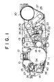
- Fig. 1 is an enlarged sectional view of a process cartridge into which the cartridge of the invention is built.
- Fig. 2 is a perspective view of a toner cartridge of the invention.
- Fig. 3 is a front sectional view of it.
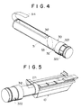
- Fig. 4 is a perspective view of a cartridge of the invention wherein a toner supplying opening is in an upper position.
- Fig. 5 is a perspective view which shows how a cartridge of the invention is constructed.
- Fig. 6 is a front view of an image forming unit which shows a collected toner conveyance means.
- Fig. 7 is a front view of a process cartridge when a toner cartridge of the invention is replaced.
- Fig. 8 is a schematic illustration of a conventional toner cartridge.
- the numeral 30 is a toner unit of the invention. As shown in Fig. 2 through Fig. 4, the toner unit 30 is equipped with the supplying toner storing container 31 and the collected toner storing unit 32, wherein both of them are separated by the partition plate 33.
- the supplying toner storing unit 31 consists of the cylindrical body 311 and an end portion, the left side end in Fig. 2, is kept covered by the cap member 313.
- the toner supplying aperture 312 is installed on the cylindrical body along the axis.
- the toner supplying aperture 312 is sealed by the flexible sealing member 314 after toner has been put in the cylindrical body 311. Refer to Fig. 4.
- the toner collecting aperture 322 is installed along the circumferential surface of the cylindrical body 321 with the inclined end plate inside, in other words the partition board 33, and the toner collecting aperture 322 is covered by the shutter 323 which can slide in the direction of the axis of the cylindrical body.
- the position of the toner collecting aperture 322 of the collected toner storing unit 32 is installed on the opposite side of the toner supplying aperture 312 of the supplying toner storing unit 31 with regard to the axis of the cylindrical drum. Therefore, when the toner unit 30 of the present invention is mounted in the mounting unit 271 on the toner storing chamber 27, the toner supplying aperture 312 is set upward as shown in Fig.
- the collected toner storing unit 32 is set on the operator's side.
- an operator holds the tip of the flexible seal and peels it off.
- the toner unit is pushed in with its toner supplying aperture is fully opened.
- the operator holds the end of the collected toner storing unit 32 and rotates it by 180° to set the toner supplying aperture 312 downward.
- the toner in the supplying toner storing unit 31 drops into the toner chamber 27 by gravity to supply the chamber with toner.
- the toner collecting aperture is set upward and it can take in the collected toner.
- the conveyance screw 40 is installed at a position of the process unit 10 to the toner receiving portion and it is set in the hollow body 41, the base end 41a of which rotates and the conveyance screw 40 penetrates the hollow body 41 from 41a through 41b.
- the discharge port 41c is installed on the lower surface of the tip 41b of the hollow body 41 and engages with the toner collecting aperture 322 in the collected toner storing unit 32 of the toner unit 30 of the present invention.
- the numeral 42 is a lever which rotates the hollow body 41 to a position where it does not interfere when the toner unit of the invention 30 is inserted into the apparatus or removed from it.
- the lever 42 can be raised around the shaft 421 in a clockwise direction.
- the pin 422 mounted on the lever slides along the lower surface of the frame member 423 which is mounted on the outer surface of the hollow body 41.
- the hollow body 41 is rotated upward around the base end 41a.
- the lever 42 is kept standing up due to the coil spring 424 which is between the lever 42 and the frame member 423.
- the feature of the invention is, in a copier toner unit which consists of a supplying toner container and a collected toner container, that they are both connected with each other through a partition board, and the partition board is inclined. For that reason, a space which toner cannot fill is not formed in the upper part of the partition board, and therefore the invention has an excellent effect on stabilizing the amount of toner held in the collected toner container.
Landscapes
- Physics & Mathematics (AREA)
- General Physics & Mathematics (AREA)
- Life Sciences & Earth Sciences (AREA)
- Engineering & Computer Science (AREA)
- Environmental & Geological Engineering (AREA)
- Sustainable Development (AREA)
- Cleaning In Electrography (AREA)
- Dry Development In Electrophotography (AREA)
Claims (5)
- Tonerbehälter zur Zufuhr eines Toners zu einem Kopiergerät und zum Sammeln eines Abfallanteils des Toners nach einem Kopiervorgang mit dem Kopiergerät, wobei der Behälter folgendes umfaßt: einen Körper (311) mit einer Tonerzufuhraufnahmekammer (31) und einer Tonerabfallsammelkammer (32), die durch eine in dem Körper (311) angebrachte Trennplatte (33) getrennt sind, einen Auslaß (312), der sich in der Wand des Körpers (311) auf der Seite der Tonerzufuhraufnahmekammer (31) befindet, um dem Kopiergerät den in der Tonerzufuhraufnahmekammer enthaltenen Toner zuzuführen und einen Einlaß (322), der sich in der Wand des Körpers (311) auf der Seite der Tonerabfallsammelkammer (32) befindet, um den Abfallanteil des Toners von dem Kopiergerät zu sammeln, dadurch gekennzeichnet, daß die Trennplatte (33) derart geneigt ist, daß eine ihrer Flächen zur Tonerabfallsammelkammer (32) gekippt ist, wobei die Einlaßseite der Tonerabfallsammelkammer kürzer als ihre gegenüberliegende Seite ist.
- Tonerbehälter nach Anspruch 1, bei dem der Körper (311) eine zylindrische Form aufweist.
- Tonerbehälter nach Anspruch 2, bei dem der Auslaß (312) und der Einlaß (322) auf gegenüberliegenden Seiten der Achse des zylindrischen Körpers (311) liegen.
- Tonerbehälter nach Anspruch 2 oder 3, bei dem sich der Auslaß (312) und der Einlaß (322) in der gekrümmten Wand des Körpers (311) befinden.
- Tonerbehälter nach einem der vorhergehenden Ansprüche 1-4, der weiterhin zur Steuerung des Ausflusses des Abfallanteils des Toners aus der Tonerabfallsammelkammer (32) ein Verschlußmittel (323) umfaßt, das am Einlaß (322) angrenzt und in bezug auf den Körper (311) axial beweglich ist.
Applications Claiming Priority (2)
| Application Number | Priority Date | Filing Date | Title |
|---|---|---|---|
| JP182857/88 | 1988-07-22 | ||
| JP63182857A JPH0233168A (ja) | 1988-07-22 | 1988-07-22 | 複写機のトナーカートリッジ |
Publications (3)
| Publication Number | Publication Date |
|---|---|
| EP0352121A2 EP0352121A2 (de) | 1990-01-24 |
| EP0352121A3 EP0352121A3 (en) | 1990-03-14 |
| EP0352121B1 true EP0352121B1 (de) | 1993-10-06 |
Family
ID=16125667
Family Applications (1)
| Application Number | Title | Priority Date | Filing Date |
|---|---|---|---|
| EP89307417A Expired - Lifetime EP0352121B1 (de) | 1988-07-22 | 1989-07-20 | Tonerbehälter für ein Kopiergerät |
Country Status (4)
| Country | Link |
|---|---|
| US (1) | US4963940A (de) |
| EP (1) | EP0352121B1 (de) |
| JP (1) | JPH0233168A (de) |
| DE (1) | DE68909705D1 (de) |
Families Citing this family (28)
| Publication number | Priority date | Publication date | Assignee | Title |
|---|---|---|---|---|
| US5079593A (en) * | 1988-06-22 | 1992-01-07 | Konica Corporation | Toner recycling mechanism detachably connected to a cartridge |
| US5020697A (en) * | 1988-06-24 | 1991-06-04 | Konica Corporation | Image recording apparatus having toner reservoir |
| EP0368598B1 (de) * | 1988-11-11 | 1994-04-06 | Konica Corporation | Toner-Wiedergewinnungsvorrichtung |
| USD320810S (en) | 1989-07-17 | 1991-10-15 | Konica Corporation | Toner cartridge for copier |
| US5109254A (en) * | 1989-08-25 | 1992-04-28 | Ricoh Company, Ltd. | Developing apparatus |
| JP2827137B2 (ja) * | 1989-12-05 | 1998-11-18 | 株式会社リコー | クリーナ・トナー・マガジン及び電子写真式記録装置 |
| JP2854911B2 (ja) * | 1990-02-06 | 1999-02-10 | 沖電気工業株式会社 | 画像形成カートリッジ及びこのカートリッジを用いる電子写真印刷装置 |
| JPH03273272A (ja) * | 1990-03-22 | 1991-12-04 | Konica Corp | 画像記録装置の現像剤収納容器 |
| JPH04372967A (ja) * | 1991-06-21 | 1992-12-25 | Toshiba Corp | 画像形成装置 |
| JP3078037B2 (ja) * | 1991-06-21 | 2000-08-21 | 株式会社東芝 | 画像形成装置 |
| JP2873522B2 (ja) * | 1991-11-14 | 1999-03-24 | 株式会社リコー | 画像形成装置 |
| JP2851208B2 (ja) * | 1992-06-30 | 1999-01-27 | 富士通株式会社 | 現像剤カ−トリッジ及びこれを用いた画像形成装置 |
| US5345298A (en) * | 1993-10-20 | 1994-09-06 | Xerox Corporation | Magnetic brush development apparatus for toner add/mix dispenser |
| US5614996A (en) * | 1994-03-03 | 1997-03-25 | Kyocera Corporation | Toner storage unit, residual toner collect unit, toner container with these units and image forming apparatus with such toner container |
| US5686985A (en) * | 1994-08-31 | 1997-11-11 | Kyocera Corporation | Toner container and developing device with the same toner container assembled therein |
| JPH0876577A (ja) | 1994-08-31 | 1996-03-22 | Kyocera Corp | トナーコンテナ |
| USD398634S (en) | 1995-10-17 | 1998-09-22 | Fuji Xerox Co., Ltd. | Toner cartridge |
| USD404758S (en) * | 1996-04-23 | 1999-01-26 | Ricoh Company, Ltd. | Toner cartridge |
| USD408053S (en) * | 1997-03-11 | 1999-04-13 | Mita Industrial Co., Ltd. | Toner cartridge |
| US5878307A (en) * | 1998-02-12 | 1999-03-02 | Nashua Corporation | Toner container having rotary seal |
| JP4105275B2 (ja) * | 1998-03-13 | 2008-06-25 | 株式会社沖データ | トナーカートリッジ、印刷プロセスカートリッジ及び電子写真記録装置 |
| JP3407797B2 (ja) * | 1999-02-09 | 2003-05-19 | 富士通株式会社 | トナー回収装置 |
| KR100462617B1 (ko) * | 2002-08-09 | 2004-12-20 | 삼성전자주식회사 | 폐현상제 용기를 구비한 습식 전자사진방식 화상형성장치 |
| JP2005227719A (ja) * | 2004-02-16 | 2005-08-25 | Fuji Xerox Co Ltd | 画像形成装置 |
| KR100694128B1 (ko) * | 2005-06-20 | 2007-03-12 | 삼성전자주식회사 | 토너카트리지 및 이를 채용한 전자사진방식 화상형성장치 |
| JP5103895B2 (ja) * | 2006-12-25 | 2012-12-19 | 富士ゼロックス株式会社 | 現像剤収容容器、並びに現像剤収容容器の組立て方法及び再生方法 |
| JP4930565B2 (ja) * | 2009-09-30 | 2012-05-16 | ブラザー工業株式会社 | 現像剤収容器および画像形成装置 |
| CN106094476A (zh) * | 2016-06-16 | 2016-11-09 | 苏州安特实业有限公司 | 一种墨粉盒 |
Citations (1)
| Publication number | Priority date | Publication date | Assignee | Title |
|---|---|---|---|---|
| JPS56146171A (en) * | 1980-04-15 | 1981-11-13 | Canon Inc | Electrophotographic copier |
Family Cites Families (5)
| Publication number | Priority date | Publication date | Assignee | Title |
|---|---|---|---|---|
| US4371015A (en) * | 1980-12-24 | 1983-02-01 | Tbs, Inc. | Toner loading system having cartridge with displaceable diaphragm |
| JPS57211176A (en) * | 1981-06-23 | 1982-12-24 | Hitachi Metals Ltd | Toner cartridge |
| JPS59184373A (ja) * | 1983-04-05 | 1984-10-19 | Fuji Xerox Co Ltd | 供給・回収トナ−ボトル |
| JPH046171A (ja) * | 1990-04-20 | 1992-01-10 | Sumitomo Special Metals Co Ltd | セラミックス接合用複合箔ろう材 |
| JPH084373A (ja) * | 1994-06-07 | 1996-01-09 | Norie Nabesawa | ドアノブ二重ロックカバー |
-
1988
- 1988-07-22 JP JP63182857A patent/JPH0233168A/ja active Pending
-
1989
- 1989-07-19 US US07/382,728 patent/US4963940A/en not_active Expired - Fee Related
- 1989-07-20 EP EP89307417A patent/EP0352121B1/de not_active Expired - Lifetime
- 1989-07-20 DE DE89307417T patent/DE68909705D1/de not_active Expired - Lifetime
Patent Citations (1)
| Publication number | Priority date | Publication date | Assignee | Title |
|---|---|---|---|---|
| JPS56146171A (en) * | 1980-04-15 | 1981-11-13 | Canon Inc | Electrophotographic copier |
Also Published As
| Publication number | Publication date |
|---|---|
| EP0352121A2 (de) | 1990-01-24 |
| DE68909705D1 (de) | 1993-11-11 |
| US4963940A (en) | 1990-10-16 |
| EP0352121A3 (en) | 1990-03-14 |
| JPH0233168A (ja) | 1990-02-02 |
Similar Documents
| Publication | Publication Date | Title |
|---|---|---|
| EP0352121B1 (de) | Tonerbehälter für ein Kopiergerät | |
| KR930007496B1 (ko) | 화상형성장치 | |
| US5289241A (en) | Developing unit for an image forming apparatus having adjoining fresh and waste toner containers | |
| JP3120723B2 (ja) | トナー容器及びこれを用いた複写機 | |
| US5260750A (en) | Image forming apparatus having integral developing agent storing and removing containers | |
| US5055881A (en) | Device for supplying a toner to a developing unit | |
| US5077584A (en) | Toner supply device for electrophotographic equipment | |
| US6122458A (en) | Replaceable developer supplying device and replaceable imaging cartridge for an image forming device | |
| JP2003295592A (ja) | 一体型トナー容器 | |
| US5475478A (en) | Developer unit and method of supplying developer | |
| US5686985A (en) | Toner container and developing device with the same toner container assembled therein | |
| US5020697A (en) | Image recording apparatus having toner reservoir | |
| US5028961A (en) | Development apparatus having a developer material storage chamber which automatically discharges upon operation of the mixer | |
| US7319837B2 (en) | Developing unit and electrophotographic image forming apparatus having the same | |
| JP2685002B2 (ja) | 電子写真装置のトナー補給機構 | |
| JP2879107B2 (ja) | トナー回収装置 | |
| JP2852934B2 (ja) | トナーカートリッジ | |
| EP0699971B1 (de) | Tonerbehälter | |
| JPH01296261A (ja) | 画像形成装置及びプロセスカートリッジ | |
| JPS60233678A (ja) | 画像形成装置と現像剤補充容器 | |
| KR930007497B1 (ko) | 화상형성장치용 토너카트리지 | |
| JP2000259061A (ja) | 画像形成装置 | |
| JPH0233169A (ja) | 複写機のトナーカートリッジ | |
| JPH05313492A (ja) | 画像形成装置 | |
| JPH09197786A (ja) | 現像装置 |
Legal Events
| Date | Code | Title | Description |
|---|---|---|---|
| PUAI | Public reference made under article 153(3) epc to a published international application that has entered the european phase |
Free format text: ORIGINAL CODE: 0009012 |
|
| AK | Designated contracting states |
Kind code of ref document: A2 Designated state(s): DE GB |
|
| PUAL | Search report despatched |
Free format text: ORIGINAL CODE: 0009013 |
|
| AK | Designated contracting states |
Kind code of ref document: A3 Designated state(s): DE GB |
|
| 17P | Request for examination filed |
Effective date: 19900818 |
|
| 17Q | First examination report despatched |
Effective date: 19920511 |
|
| GRAA | (expected) grant |
Free format text: ORIGINAL CODE: 0009210 |
|
| AK | Designated contracting states |
Kind code of ref document: B1 Designated state(s): DE GB |
|
| PG25 | Lapsed in a contracting state [announced via postgrant information from national office to epo] |
Ref country code: DE Effective date: 19931006 |
|
| REF | Corresponds to: |
Ref document number: 68909705 Country of ref document: DE Date of ref document: 19931111 |
|
| PLBE | No opposition filed within time limit |
Free format text: ORIGINAL CODE: 0009261 |
|
| STAA | Information on the status of an ep patent application or granted ep patent |
Free format text: STATUS: NO OPPOSITION FILED WITHIN TIME LIMIT |
|
| 26N | No opposition filed | ||
| PGFP | Annual fee paid to national office [announced via postgrant information from national office to epo] |
Ref country code: GB Payment date: 19960711 Year of fee payment: 8 |
|
| PG25 | Lapsed in a contracting state [announced via postgrant information from national office to epo] |
Ref country code: GB Free format text: LAPSE BECAUSE OF NON-PAYMENT OF DUE FEES Effective date: 19970720 |
|
| GBPC | Gb: european patent ceased through non-payment of renewal fee |
Effective date: 19970720 |