EP0352154A1 - Gesteuerte Schweisszange und deren Verwendungsverfahren - Google Patents
Gesteuerte Schweisszange und deren Verwendungsverfahren Download PDFInfo
- Publication number
- EP0352154A1 EP0352154A1 EP89401819A EP89401819A EP0352154A1 EP 0352154 A1 EP0352154 A1 EP 0352154A1 EP 89401819 A EP89401819 A EP 89401819A EP 89401819 A EP89401819 A EP 89401819A EP 0352154 A1 EP0352154 A1 EP 0352154A1
- Authority
- EP
- European Patent Office
- Prior art keywords
- clamp
- welding
- electrodes
- microcomputer
- arms
- Prior art date
- Legal status (The legal status is an assumption and is not a legal conclusion. Google has not performed a legal analysis and makes no representation as to the accuracy of the status listed.)
- Withdrawn
Links
- 238000003466 welding Methods 0.000 title claims abstract description 34
- 238000000034 method Methods 0.000 title claims description 8
- 230000004044 response Effects 0.000 claims abstract description 3
- 229910000679 solder Inorganic materials 0.000 claims description 3
- 238000004891 communication Methods 0.000 description 1
- 239000004020 conductor Substances 0.000 description 1
- 238000004519 manufacturing process Methods 0.000 description 1
- 238000003032 molecular docking Methods 0.000 description 1
- 238000005457 optimization Methods 0.000 description 1
- 238000010248 power generation Methods 0.000 description 1
- 230000033764 rhythmic process Effects 0.000 description 1
- 230000035939 shock Effects 0.000 description 1
Images
Classifications
-
- B—PERFORMING OPERATIONS; TRANSPORTING
- B23—MACHINE TOOLS; METAL-WORKING NOT OTHERWISE PROVIDED FOR
- B23K—SOLDERING OR UNSOLDERING; WELDING; CLADDING OR PLATING BY SOLDERING OR WELDING; CUTTING BY APPLYING HEAT LOCALLY, e.g. FLAME CUTTING; WORKING BY LASER BEAM
- B23K11/00—Resistance welding; Severing by resistance heating
- B23K11/30—Features relating to electrodes
- B23K11/31—Electrode holders and actuating devices therefor
- B23K11/311—Electrode holders and actuating devices therefor the actuating device comprising an electric motor
-
- B—PERFORMING OPERATIONS; TRANSPORTING
- B23—MACHINE TOOLS; METAL-WORKING NOT OTHERWISE PROVIDED FOR
- B23K—SOLDERING OR UNSOLDERING; WELDING; CLADDING OR PLATING BY SOLDERING OR WELDING; CUTTING BY APPLYING HEAT LOCALLY, e.g. FLAME CUTTING; WORKING BY LASER BEAM
- B23K11/00—Resistance welding; Severing by resistance heating
- B23K11/30—Features relating to electrodes
- B23K11/31—Electrode holders and actuating devices therefor
- B23K11/314—Spot welding guns, e.g. mounted on robots
Definitions
- the present invention relates to a slave welding tongs and to its method of use.
- Welding tongs commonly used on welding robots in the automotive industry, work thanks to a drawer distributor which acts by all or nothing.
- a drawer distributor which acts by all or nothing.
- compressed air is sent to a booster which compresses oil which, in turn, is sent to the cylinder to move it in one direction or the other and control either the opening or the clamp closing.
- the pressure build-up time inside the control cylinder is relatively long and, as the pressure control system is not very precise, it is only 20 or 30% sure that the right pressure is established, a time delay is added to allow the pressure to build up.
- a solenoid valve opens the compressed air to trigger the rise in pressure of the oil in the booster and it is only 180 milliseconds after the solder can be sent.
- the control is carried out by all or nothing by the fact that a relay sticks from a certain value of oil pressure and this pressure sensor currently used is unsatisfactory because of insufficient precision.
- a good pressure sensor is expensive. If we consider that a clamp performs up to eighty solder points per cycle, we see that the robot, which is equipped with such a clamp, ultimately operates at a fairly slow pace, rhythm slowed by time lost when opening and closing the clamp as well as establishing pressure.
- a welding gun essentially comprises as active elements two electrodes which should be monitored the degree of wear to know when it becomes opportune to file or change them, otherwise the electrodes mat, the surface in contact with the sheet increases and the work performed is of poor quality.
- the present invention makes it possible to avoid the aforementioned drawbacks with a slave welding clamp of the type comprising a device for driving one of the arms of the clamp relative to the other arm and using a position sensor to determine at any time. the spacing of its electrodes.
- an electric motor of the type without collectors drives a roller screw linked to the two arms of the clamp.
- this slave welding clamp is associated with a control microcomputer.
- the microcomputer includes a memory which contains the value of the spacing of the electrodes of the clamp and it constantly compares this value with that read and transmitted by the position sensor, so that it deduces therefrom a value d error and sends a correction value to a drive controlling this motor.
- the present invention relates to a method of using a slave welding clamp having all or some of the characteristics described above, a method remarkable in that it includes an automatic setting of the zero opening of the electrodes at the start of each welding cycle.
- the microcomputer sends the order "welding request" to the ad hoc annex electrical equipment when it finds the "tight sheets" position of the arms of the clamp via the position sensor.
- the microcomputer can be equipped with alarms warning that a patching of the electrodes 9 is necessary then that the state of wear of the electrodes requires their change.
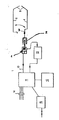
- a welding clamp controlled in position by hypothesis includes a movable arm 4 and a fixed arm 5.
- the movable arm 4 is rotated around the joint 3 of the clamp by the roller screw 2 driven by the electric motor 1.
- a position sensor 7 permanently gives the distance that between them the movable arm 4 and the fixed arm 5 of the clamp.
- the electric motor 1 is driven in both directions by a variator 10 controlled by a microcomputer 11 which permanently receives the information provided by the position sensor 7 by a conductor 13.
- the microcomputer 11 contains in its RAM memory 12 the spacing value of the electrodes 9 of the welding gun. It compares this value with that read and transmitted by the angular position sensor 7. It deduces therefrom an error value which, multiplied by a gain K, gives the value of the correction current which it sends to the variator 10.
- the loading the spacing value of the electrodes 9 of the welding gun in the RAM memory 12 can be carried out in parallel by the logic inputs 14 of the microcomputer 11. It can also be carried out using its serial link 15. This serial link allows communication with a robot, centralized control or any other system which itself has a serial link.
- the microcomputer controls the opening of the servovalve 8, which amounts to supplying the jack 1 with the maximum flow rate in the direction of closing of the clamp.
- the electrodes 9 of the clamp are closed to reach a defined position, on the one hand, by the contact between the two electrodes and, on the other hand, by the maximum pressure on the jack.
- the microcomputer sends the order to weld to a welding cabinet.
- the box responds to the microcomputer which controls the programmed opening of the clamp.
- the clamp Before reaching this value, the clamp goes through a second position threshold which is detected by the microcomputer. The latter then sends an order which can order the movement of the robot or the machine on which the welding tongs are installed to go and perform another welding a little further and so on from place to place.
- the electrodes of the welding gun wear out.
- the zero position corresponds to the pressure contact of the electrodes to the point that, in this position, the arms 4 and 5 of the welding tongs are curved inwards. As it wears out, the zero position will deviate from the closed clamp position.
- an automatic zeroing procedure is programmed in the microcomputer 11. With the system illustrated in the drawing, the distance between the electrodes 9 can be adjusted to the minimum value compatible with the obstacles to be avoided during the movement of the clamp from one welding point to the next. Since this distance is adjustable to its minimum value, the closing time of the clamp until its electrodes are in contact and their opening times can be minimal.
- the microcomputer performs a permanent analysis of the entire device and can report faults. It allows automatic wear compensation of the electrodes at each robot machine cycle and signals when the electrodes 9 must be changed or repaired.
Landscapes
- Engineering & Computer Science (AREA)
- Mechanical Engineering (AREA)
- Robotics (AREA)
- Resistance Welding (AREA)
Applications Claiming Priority (2)
| Application Number | Priority Date | Filing Date | Title |
|---|---|---|---|
| FR8809915 | 1988-07-22 | ||
| FR8809915A FR2634408A1 (fr) | 1988-07-22 | 1988-07-22 | Pince de soudage asservie et son procede d'utilisation |
Publications (1)
| Publication Number | Publication Date |
|---|---|
| EP0352154A1 true EP0352154A1 (de) | 1990-01-24 |
Family
ID=9368671
Family Applications (1)
| Application Number | Title | Priority Date | Filing Date |
|---|---|---|---|
| EP89401819A Withdrawn EP0352154A1 (de) | 1988-07-22 | 1989-06-27 | Gesteuerte Schweisszange und deren Verwendungsverfahren |
Country Status (2)
| Country | Link |
|---|---|
| EP (1) | EP0352154A1 (de) |
| FR (1) | FR2634408A1 (de) |
Cited By (3)
| Publication number | Priority date | Publication date | Assignee | Title |
|---|---|---|---|---|
| FR2728820A1 (fr) * | 1994-12-30 | 1996-07-05 | Renault | Dispositif de soudage par resistance asservi en effort |
| WO2001058636A1 (de) * | 2000-02-09 | 2001-08-16 | Reu-Schweisstechnik Gmbh | Widerstandspunktschweiss-steuervorrichtung und -steuerverfahren |
| WO2001085379A1 (en) * | 2000-05-10 | 2001-11-15 | Corus Uk Limited | Single sided resistance welding |
Citations (2)
| Publication number | Priority date | Publication date | Assignee | Title |
|---|---|---|---|---|
| FR2464781A1 (fr) * | 1979-09-13 | 1981-03-20 | Renault | Pince de soudure asservie et son procede d'utilisation |
| FR2585976A1 (fr) * | 1985-08-09 | 1987-02-13 | Aro | Machine de soudage par resistance a commande numerique et systeme vis et ecrou ou analogue |
-
1988
- 1988-07-22 FR FR8809915A patent/FR2634408A1/fr not_active Withdrawn
-
1989
- 1989-06-27 EP EP89401819A patent/EP0352154A1/de not_active Withdrawn
Patent Citations (2)
| Publication number | Priority date | Publication date | Assignee | Title |
|---|---|---|---|---|
| FR2464781A1 (fr) * | 1979-09-13 | 1981-03-20 | Renault | Pince de soudure asservie et son procede d'utilisation |
| FR2585976A1 (fr) * | 1985-08-09 | 1987-02-13 | Aro | Machine de soudage par resistance a commande numerique et systeme vis et ecrou ou analogue |
Cited By (6)
| Publication number | Priority date | Publication date | Assignee | Title |
|---|---|---|---|---|
| FR2728820A1 (fr) * | 1994-12-30 | 1996-07-05 | Renault | Dispositif de soudage par resistance asservi en effort |
| WO1996020805A1 (fr) * | 1994-12-30 | 1996-07-11 | Regie Nationale Des Usines Renault | Dispositif de soudage par resistance asservi en effort |
| US6204468B1 (en) * | 1994-12-30 | 2001-03-20 | Regie Nationale Des Usines Renault | Force-controlled resistance welding device |
| WO2001058636A1 (de) * | 2000-02-09 | 2001-08-16 | Reu-Schweisstechnik Gmbh | Widerstandspunktschweiss-steuervorrichtung und -steuerverfahren |
| US6906276B2 (en) | 2000-02-09 | 2005-06-14 | Reu-Schweisstechnik Gmbh | Resistance spot welding control device and method |
| WO2001085379A1 (en) * | 2000-05-10 | 2001-11-15 | Corus Uk Limited | Single sided resistance welding |
Also Published As
| Publication number | Publication date |
|---|---|
| FR2634408A1 (fr) | 1990-01-26 |
Similar Documents
| Publication | Publication Date | Title |
|---|---|---|
| US5340960A (en) | Control apparatus for spot welding robot | |
| US5321225A (en) | Installation for controlling tooling including a clamp for performing a determined operation on workpieces, relative displacement of the clamp and said workpieces being controlled by an automatic positioning system | |
| US6378194B1 (en) | Method for joining workpieces, and pressing device therefor | |
| US4553319A (en) | Method for connecting the ends of stator windings to the stator supply terminals | |
| US5070226A (en) | Interactive stud welding gun | |
| KR100217545B1 (ko) | 전동가압식 건의 전극가압 구동방법 및 장치 | |
| CA2189409A1 (en) | Current Collector for Transmitting Energy Between a Contact Wire and a Motor Coach | |
| US4984171A (en) | Control method and apparatus for automatic welding machine | |
| CA1253723A (en) | Friction welding apparatus | |
| CN118889083A (zh) | 一种用于带电接引线作业的自适应线夹 | |
| US7420137B2 (en) | Method of open and/or closed-loop control of the movement of welding tongs | |
| EP0352154A1 (de) | Gesteuerte Schweisszange und deren Verwendungsverfahren | |
| EP0816005A3 (de) | Punktschweissvorrichtung und ein Verfahren zur Kontrolle der Vorrichtung | |
| EP0278185B1 (de) | Numerisch gesteuerte Widerstandsschweissmaschine und Bolzen- und Mutter-System oder Analogisches; ihre Funktionsweise | |
| EP0801600B1 (de) | Kraftgesteuerte widerstandschweissvorrichtung | |
| EP0220983B1 (de) | Verfahren und Vorrichtung zur Suche der optimalen Schraubposition für grosse Bolzen | |
| WO2000041488A3 (en) | Welding machine | |
| FR2464781A1 (fr) | Pince de soudure asservie et son procede d'utilisation | |
| FR2574334A1 (fr) | Systeme de manipulation de pieces de montage | |
| JP2860879B2 (ja) | ガン加圧駆動装置 | |
| CN116021220A (zh) | 一种除污器生产用焊接装置 | |
| EP1054749B1 (de) | Widerstandschweisszangen mit einer mechanischen teilungs- und rücksetzvorrichtung | |
| SU770869A1 (ru) | Токоприемник | |
| JP3700906B2 (ja) | 電動ガン | |
| CN215966119U (zh) | 锻造操作机夹持驱动组件 |
Legal Events
| Date | Code | Title | Description |
|---|---|---|---|
| PUAI | Public reference made under article 153(3) epc to a published international application that has entered the european phase |
Free format text: ORIGINAL CODE: 0009012 |
|
| 17P | Request for examination filed |
Effective date: 19890630 |
|
| AK | Designated contracting states |
Kind code of ref document: A1 Designated state(s): DE ES FR GB IT SE |
|
| STAA | Information on the status of an ep patent application or granted ep patent |
Free format text: STATUS: THE APPLICATION IS DEEMED TO BE WITHDRAWN |
|
| 18D | Application deemed to be withdrawn |
Effective date: 19900725 |