EP1054749B1 - Widerstandschweisszangen mit einer mechanischen teilungs- und rücksetzvorrichtung - Google Patents
Widerstandschweisszangen mit einer mechanischen teilungs- und rücksetzvorrichtung Download PDFInfo
- Publication number
- EP1054749B1 EP1054749B1 EP99901683A EP99901683A EP1054749B1 EP 1054749 B1 EP1054749 B1 EP 1054749B1 EP 99901683 A EP99901683 A EP 99901683A EP 99901683 A EP99901683 A EP 99901683A EP 1054749 B1 EP1054749 B1 EP 1054749B1
- Authority
- EP
- European Patent Office
- Prior art keywords
- clamp
- cam
- indexing
- welding
- roller
- Prior art date
- Legal status (The legal status is an assumption and is not a legal conclusion. Google has not performed a legal analysis and makes no representation as to the accuracy of the status listed.)
- Expired - Lifetime
Links
- 238000003466 welding Methods 0.000 title claims abstract description 41
- 230000000903 blocking effect Effects 0.000 claims 1
- 239000003638 chemical reducing agent Substances 0.000 claims 1
- 238000003032 molecular docking Methods 0.000 description 3
- 230000001133 acceleration Effects 0.000 description 2
- 230000000694 effects Effects 0.000 description 1
- 238000003780 insertion Methods 0.000 description 1
- 230000037431 insertion Effects 0.000 description 1
- 238000005259 measurement Methods 0.000 description 1
- 230000002093 peripheral effect Effects 0.000 description 1
Images
Classifications
-
- B—PERFORMING OPERATIONS; TRANSPORTING
- B23—MACHINE TOOLS; METAL-WORKING NOT OTHERWISE PROVIDED FOR
- B23K—SOLDERING OR UNSOLDERING; WELDING; CLADDING OR PLATING BY SOLDERING OR WELDING; CUTTING BY APPLYING HEAT LOCALLY, e.g. FLAME CUTTING; WORKING BY LASER BEAM
- B23K11/00—Resistance welding; Severing by resistance heating
- B23K11/30—Features relating to electrodes
- B23K11/31—Electrode holders and actuating devices therefor
- B23K11/314—Spot welding guns, e.g. mounted on robots
Definitions
- the present invention relates to an electric welding pliers comprising a device for indexing and de-indexing, i.e. locking and unlocking of the gripper movement, for example the rotation in the case of an X clamp or translation in the case of a J-clamp, relative to its support, by example a robot arm on which said clamp is climb.
- a welding cycle is broken down into three phases: docking, welding and clearance.
- a clamp to be welded must be able to admit movement, for example opening and closing, relative to the robot in order to adapt to the sheets to be assembled, in particular when docking which corresponds to the insertion of overlapping two pieces to be welded between the clamp electrodes and establishing a stabilized force of the two electrodes creating an electrical circuit.
- the clamp is then opened and brought by the robot to another welding point at carry out.
- Welding tongs with electric motorization generally used have an indexing and deindexing system constituted by a jack whose position of rod extended allows to block the clamp and whose rod position retracted releases the movement of said clamp to allow self-centering electrodes on a sheet to be assembled during docking without constraint on the sheets.
- the clamp In order to promote self-centering, the clamp has springs balancing to bring the clamp to a position of equilibrium around its welding plane.
- the presence of the cylinder implies, in addition to the circuit electric motorized gripper, the presence of a compressed air circuit as well as all the elements which flow, namely a pipeline, a compressor, etc.
- the present invention therefore aims to overcome these disadvantages by proposing a motorized welding pliers electric in which the locking device and unlocking the movement of the welding gun relative to in terms of welding, no longer requires a power supply pneumatic, hydraulic and others.
- the present invention relates to a pliers weld with electric motorization of the type comprising an arm fixed indexed and a movable arm, respectively provided with a electrode, as well as an indexing and de-indexing locking and unlocking the movement of the clamp relative to the welding plane, characterized in that said indexing and de-indexing device comprises mechanical means arranged to ensure said locking and said unlocking of said movement of the clamp, during opening / closing movements of said clamp, under the effect of the electrical control means for opening and clamp closing.
- a welding gun according to the invention can also be a X-clip than a J-clip
- the mechanical means of the indexing device and deindexing of the clamp consist of a cam, a connecting rod and a roller, the cam being rotatably mounted around its axis of attachment to an ear of the desired fixed arm of the clamp, the connecting rod having a rotatably mounted end around its axis of connection with the cam, said axis of link being parallel to the cam fixing axis and away from it, and one end rotatably mounted around a motor journal whose longitudinal axis is also parallel to the axis of rotation of the cam, said journal motor itself in sliding pivot connection with the ear of the second arm of the desired movable clamp, the roller being in turn secured to the joint of the clamp and suitable for cooperating with the profile of the cam.
- the roller is mounted, by means of a indexing device support, integral with the joint of the clamp, the axis of the roller being parallel to the axis of fixing of the cam, said roller being able to roll along the cam profile and said roller being further mounted sliding relative to its support, sliding in translation being limited by an elastic return means such than an elastomeric part.
- the cam has a profile defined by different radii defining different cam diameters and, when the roller rolls along the largest cam diameter, the arms of the clamp having a rotational movement around the joint of the pliers are indexed.
- a welding gun according to the invention therefore no longer has only one power supply and therefore it is no longer need pneumatic or hydraulic supply for the indexing and de-indexing device. We thus remove also all circuits and components that arise from a other supply such as pneumatic, for example, pipes, compressor, etc.
- a welding pliers according to the invention additionally provides additional security in the measurement where, in the absence of energy from the clamp, the clamp and particular the indexing and deindexing device remains in position and the clamp remains manually usable.
- a welding pliers is obtained in which the speed of indexing and de-indexing does not depend on the speed of a cylinder but the speed of the electric motor gripper actuation.
- the roller running on the cam gives indexing smoothness unlike a cylinder that hits the finger.
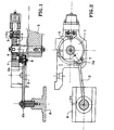
- this comprises a fixed indexed arm 5 and a movable arm, the indexing or deindexing device acts on the entire clamp so as to lock or not the relative rotation of the arms.
- the indexing and de-indexing device comprises a cam 1, a connecting rod 2 and an average elastic-roller return system 3.
- the ear of the support of the desired arm 5 fixes the clamp has a finger 4 constituting the axis of the cam 1 and on which is rotatably mounted on cam 1.
- One end of the connecting rod 2 operates with said cam 1 via a connecting piece 7 secured to the underside of said cam 1, preferably in the vicinity of the peripheral edge of said cam 1, and having an axis 6, parallel to finger 4, on which the end 2a of the connecting rod 2 is rotatably mounted.
- the second end 2b of the connecting rod 2 is rotatably mounted around a motor journal 8 which is in pivot connection sliding with the ear of the other arm of the desired clamp mobile.
- the motor journal 8 generally consists of a nut sliding mounted along a screw coupled to the reduction gear the electric motorization of the gripper.
- the roller 3 is mounted, by means of a support of the indexing device, integral with the articulation of the gripper, the axis of the roller 3 being parallel to the axis of the finger 4 on which the cam 1 is mounted, said roller 3 being able to roll along the cam profile.
- roller 3 is slidably mounted relative to its support, sliding in translation being limited by a elastic return means such as an elastomeric part.
- said clamp indexes as soon as the movable arm of the clamp is approximately 5 mm from the theoretical plane of welding.
- the distance between the electrodes is then 10 mm and at the end of 15 mm indexing.
- the clamp remains indexed for total opening.
- the dimensioning of the various elements constituting the indexing and de-indexing device is determined for each clamp size according to the previous values desired intervals between the clamp electrodes.
Landscapes
- Engineering & Computer Science (AREA)
- Mechanical Engineering (AREA)
- Robotics (AREA)
- Resistance Welding (AREA)
- Connections Effected By Soldering, Adhesion, Or Permanent Deformation (AREA)
- Machine Tool Positioning Apparatuses (AREA)
- Pressure Welding/Diffusion-Bonding (AREA)
- Manufacture Of Motors, Generators (AREA)
- Processing Of Terminals (AREA)
- Manufacturing Of Electrical Connectors (AREA)
- Lining Or Joining Of Plastics Or The Like (AREA)
- Crushing And Grinding (AREA)
Claims (9)
- Schweißzange mit elektrischem Antrieb, umfassend einen gerasterten ortsfesten Arm (5) und einen beweglichen Arm, die jeweils mit einer Elektrode versehen sind, sowie eine Teilungs- und Rücksetzvorrichtung, welche die Bewegung der Schweißzange bezogen auf die Schweißebene sperrt und freigibt,
dadurch gekennzeichnet, daß die besagte Teilungs- und Rücksetzvorrichtung mechanische Mittel (1, 2, 3) umfaßt, die so angeordnet sind, daß sie die besagte Sperrung und Freigabe der besagten Bewegung der Schweißzange im Verlauf der Öffnungs-/Schließbewegungen der besagten Schweißzange unter der Einwirkung der Mittel zur elektrischen Öffnungs- und Schließbetätigung der Schweißzange sicherstellen. - Schweißzange nach Anspruch 1,
dadurch gekennzeichnet, daß die Schweißzange eine J-förmige Zange ist. - Schweißzange nach Anspruch 1,
dadurch gekennzeichnet, daß die Schweißzange eine X-förmige Zange ist. - Schweißzange nach Anspruch 3,
dadurch gekennzeichnet, daß die mechanischen Mittel der Teilungs- und Rücksetzvorrichtung der Schweißzange aus einem Nocken (1), einer Gelenkstange (2) und einer Rolle (3) bestehen, wobei der Nocken (1) drehbar um seine Befestigungsachse an einer Nase des als ortsfest vorgesehenen Arms (5) der Schweißzange gelagert ist, während die Gelenkstange (2) ein Ende (2a) aufweist, das drehbar um seine Verbindungsachse (6) mit dem Nocken (1) gelagert ist, wobei die besagte Verbindungsachse (6) parallel zur Befestigungsachse des Nockens (1) verläuft und zu dieser beabstandet ist, sowie ein Ende (2b), das drehbar um einen Antriebszapfen (8) gelagert ist, dessen Längsachse ebenfalls parallel zur Drehachse des Nockens (1) verläuft, wobei sich der besagte Antriebszapfen (8) selbst in einer Gleitzapfenverbindung mit der Nase des als beweglich vorgesehenen zweiten Arms der Schweißzange befindet, während die Rolle (3) ihrerseits fest mit dem Gelenk der Schweißzange verbunden ist und mit dem Profil des Nockens (1) zusammenwirken kann. - Schweißzange nach Anspruch 4,
dadurch gekennzeichnet, daß der Nocken (1) unterschiedliche Durchmesser aufweist, wobei der größte Durchmesser des Nockens der Teilung der Schweißzange entspricht. - Schweißzange nach einem der Ansprüche 4 und 5,
dadurch gekennzeichnet, daß die Befestigungsachse des Nockens (1) aus einem Finger (4) besteht, der fest mit der Nase des als ortsfest vorgesehenen Arms (5) der Schweißzange verbunden ist. - Schweißzange nach einem der Ansprüche 4 bis 6,
dadurch gekennzeichnet, daß das Ende (2a) der Gelenkstange (2) mit dem Nocken (1) über ein Verbindungsteil (7) zusammenwirkt, das fest mit der Unterseite des Nockens (1) verbunden ist und eine Achse (6) aufweist, an der das Ende (2a) drehbar gelagert ist. - Schweißzange nach einem der Ansprüche 4 bis 7,
dadurch gekennzeichnet, daß die Rolle (3) über einen Träger der Teilungsvorrichtung fest mit dem Gelenk der Schweißzange verbunden gelagert ist, wobei die Achse der Rolle (3) parallel zur Befestigungsachse des Nockens (1) verläuft, wobei die besagte Rolle (3) am Profil des Nockens (1) entlang rollen kann und wobei die besagte Rolle (3) außerdem im Verhältnis zur ihrem Träger verschiebbar gelagert ist, wobei die geradlinige Verschiebung durch ein elastisches Rückstellmittel begrenzt wird. - Schweißzange nach einem der Ansprüche 4 bis 8,
dadurch gekennzeichnet, daß der Antriebszapfen (8) aus einer Mutter besteht, die an einer Schraube entlang verschiebbar gelagert ist, die an das Untersetzungsgetriebe des elektrischen Antriebs der Schweißzange gekoppelt ist.
Applications Claiming Priority (3)
| Application Number | Priority Date | Filing Date | Title |
|---|---|---|---|
| FR9801153 | 1998-02-02 | ||
| FR9801153A FR2774320B1 (fr) | 1998-02-02 | 1998-02-02 | Pince a souder electrique comportant un dispositif d'indexage et de desindexage mecanique |
| PCT/FR1999/000208 WO1999038640A1 (fr) | 1998-02-02 | 1999-02-02 | Pince a souder electrique comportant un dispositif d'indexage et de desindexage mecanique |
Publications (2)
| Publication Number | Publication Date |
|---|---|
| EP1054749A1 EP1054749A1 (de) | 2000-11-29 |
| EP1054749B1 true EP1054749B1 (de) | 2003-05-21 |
Family
ID=9522461
Family Applications (1)
| Application Number | Title | Priority Date | Filing Date |
|---|---|---|---|
| EP99901683A Expired - Lifetime EP1054749B1 (de) | 1998-02-02 | 1999-02-02 | Widerstandschweisszangen mit einer mechanischen teilungs- und rücksetzvorrichtung |
Country Status (16)
| Country | Link |
|---|---|
| US (1) | US6392185B1 (de) |
| EP (1) | EP1054749B1 (de) |
| JP (1) | JP2002501831A (de) |
| KR (1) | KR20010040527A (de) |
| CN (1) | CN1289279A (de) |
| AT (1) | ATE240815T1 (de) |
| AU (1) | AU2170099A (de) |
| BR (1) | BR9907171A (de) |
| CA (1) | CA2320330A1 (de) |
| DE (1) | DE69908093T2 (de) |
| ES (1) | ES2198882T3 (de) |
| FR (1) | FR2774320B1 (de) |
| RO (1) | RO120054B1 (de) |
| SI (1) | SI20314A (de) |
| TR (1) | TR200002167T2 (de) |
| WO (1) | WO1999038640A1 (de) |
Families Citing this family (4)
| Publication number | Priority date | Publication date | Assignee | Title |
|---|---|---|---|---|
| FR2829412B1 (fr) * | 2001-09-10 | 2003-12-12 | Fiam | Pince a souder par points a motorisation electrique comportant un dispositif d'indexage et de desindexage electrique |
| ES2266829T3 (es) | 2002-02-05 | 2007-03-01 | Swac Electronic Gmbh | Dispositivo de accionamiento para unas pinzas portaelectrodos. |
| CN101653892B (zh) * | 2009-09-14 | 2012-05-23 | 奇瑞汽车股份有限公司 | 一种焊钳导向机构 |
| CN102699591B (zh) * | 2012-06-19 | 2014-11-26 | 奇瑞汽车股份有限公司 | 焊钳导向装置 |
Family Cites Families (10)
| Publication number | Priority date | Publication date | Assignee | Title |
|---|---|---|---|---|
| FR2255136A1 (en) * | 1973-12-21 | 1975-07-18 | Mitsubishi Heavy Ind Ltd | Spot welding gun fixed on wrist of industrial robot - with electrodes clamped by air cylinder housed in the wrist |
| FR2490128A1 (fr) * | 1980-09-16 | 1982-03-19 | Honda Motor Co Ltd | Pince a souder |
| US5223686A (en) * | 1990-10-31 | 1993-06-29 | Cajon Company | Orbital welding apparatus with safety interlock |
| US5225647A (en) * | 1991-11-04 | 1993-07-06 | Unitek Equipment Inc. | Motorized weld head |
| US5386092A (en) * | 1991-11-04 | 1995-01-31 | Unitek Equipment Inc. | Fast response weld head |
| DE69406614T2 (de) * | 1993-08-25 | 1998-06-25 | Toyota Motor Co Ltd | Steuerverfahren zum Punktschweissen, und Vorrichtung die eine gesteuerte Schweisszange benützt |
| JPH07232282A (ja) * | 1994-02-25 | 1995-09-05 | Obara Kk | C型溶接ガンの制御装置 |
| US5705783A (en) * | 1995-07-05 | 1998-01-06 | Ford Motor Company | Copper core weld gun |
| JP3755843B2 (ja) * | 1996-09-30 | 2006-03-15 | Obara株式会社 | 加圧型抵抗溶接機の制御方法 |
| JP2000288743A (ja) * | 1999-02-03 | 2000-10-17 | Dengensha Mfg Co Ltd | 抵抗溶接機用制御装置 |
-
1998
- 1998-02-02 FR FR9801153A patent/FR2774320B1/fr not_active Expired - Fee Related
-
1999
- 1999-02-02 SI SI9920022A patent/SI20314A/sl unknown
- 1999-02-02 DE DE69908093T patent/DE69908093T2/de not_active Expired - Fee Related
- 1999-02-02 BR BR9907171-1A patent/BR9907171A/pt not_active IP Right Cessation
- 1999-02-02 CN CN99802614A patent/CN1289279A/zh active Pending
- 1999-02-02 AT AT99901683T patent/ATE240815T1/de not_active IP Right Cessation
- 1999-02-02 WO PCT/FR1999/000208 patent/WO1999038640A1/fr not_active Ceased
- 1999-02-02 CA CA002320330A patent/CA2320330A1/fr not_active Abandoned
- 1999-02-02 US US09/601,401 patent/US6392185B1/en not_active Expired - Fee Related
- 1999-02-02 JP JP2000529921A patent/JP2002501831A/ja not_active Withdrawn
- 1999-02-02 KR KR1020007008391A patent/KR20010040527A/ko not_active Withdrawn
- 1999-02-02 RO ROA200000770A patent/RO120054B1/ro unknown
- 1999-02-02 AU AU21700/99A patent/AU2170099A/en not_active Abandoned
- 1999-02-02 ES ES99901683T patent/ES2198882T3/es not_active Expired - Lifetime
- 1999-02-02 TR TR2000/02167T patent/TR200002167T2/xx unknown
- 1999-02-02 EP EP99901683A patent/EP1054749B1/de not_active Expired - Lifetime
Also Published As
| Publication number | Publication date |
|---|---|
| AU2170099A (en) | 1999-08-16 |
| CA2320330A1 (fr) | 1999-08-05 |
| TR200002167T2 (tr) | 2000-11-21 |
| RO120054B1 (ro) | 2005-08-30 |
| FR2774320B1 (fr) | 2000-02-25 |
| JP2002501831A (ja) | 2002-01-22 |
| CN1289279A (zh) | 2001-03-28 |
| BR9907171A (pt) | 2000-10-10 |
| SI20314A (sl) | 2001-02-28 |
| DE69908093T2 (de) | 2004-02-19 |
| ATE240815T1 (de) | 2003-06-15 |
| WO1999038640A1 (fr) | 1999-08-05 |
| US6392185B1 (en) | 2002-05-21 |
| KR20010040527A (ko) | 2001-05-15 |
| EP1054749A1 (de) | 2000-11-29 |
| FR2774320A1 (fr) | 1999-08-06 |
| DE69908093D1 (de) | 2003-06-26 |
| ES2198882T3 (es) | 2004-02-01 |
Similar Documents
| Publication | Publication Date | Title |
|---|---|---|
| EP0179002B1 (de) | Einrichtung zum automatischen Schliessen, sowie zum Offenhalten von Türen | |
| FR2507520A1 (fr) | Pince pour dispositif de levage destine a la manutention de pieces | |
| CA2275958A1 (fr) | Outil pilote de centrage et serrage | |
| EP1054749B1 (de) | Widerstandschweisszangen mit einer mechanischen teilungs- und rücksetzvorrichtung | |
| EP1369276A1 (de) | Hintere Haube für Kraftfahrzeug | |
| FR2578889A1 (fr) | Arrangement de ressorts a gaz comme dispositif d'equilibrage de poids et de retenue pour des pieces pouvant essentiellement pivoter autour d'un axe horizontal | |
| FR2611549A3 (fr) | Cisaille motorisee auto-alimentee | |
| FR2758520A1 (fr) | Systeme de porte, en particulier pour un avion version passagers | |
| EP1122031A1 (de) | Spann-Wekzeug und insbesondere Krimp-Wekzeug | |
| EP0726123B1 (de) | Roboterverbundenes Werkzeug zum Montieren von Dichtungsstreifen | |
| FR2730659A1 (fr) | Pince de prehension pour manipulateur | |
| FR2758522A1 (fr) | Systeme de porte, en particulier pour un avion version passagers | |
| FR2646202A1 (fr) | Dispositif de manoeuvre pour l'ouverture et la fermeture d'au moins un volet | |
| FR2642691A1 (fr) | Appareil destine a etre fixe sur un poignet de robot pour assurer la pose d'un joint de porte | |
| EP0845332B1 (de) | Vorrichtung zum Befestigen von Dichtungslippen | |
| EP0836099B1 (de) | Öffnungsanordnung für Zange insbesondere Strommesszange | |
| FR2820069A1 (fr) | Dispositif de referencement de la position angulaire d'un vilebrequin, ou equivalent, a au moins un poste d'usinage ou de traitement | |
| EP1072366A1 (de) | Fördereinrichtung | |
| FR2517580A1 (fr) | Dispositif pour fixer en position des porte-pieces sur des machines-outils | |
| FR2581914A1 (fr) | Dispositif de prehension de pieces pour robot manipulateur | |
| EP0138643B1 (de) | Betätigungsvorrichtung für Eisenbahnselbstentladewagentüren und damit ausgestattete Entlader | |
| EP1788176B1 (de) | Türscharnier mit integriertem Türfeststeller | |
| EP1375046B1 (de) | Tragbare Punktschweisszange | |
| EP1427561A1 (de) | Elektrisch angetriebene punktschweisszange mit einer elektrischen schalt- und rücksetzvorrichtung | |
| BE1003725A3 (fr) | Agencement pour l'ouverture et la fermeture de la porte d'un vehicule mobile, tel qu'un vehicule a passagers. |
Legal Events
| Date | Code | Title | Description |
|---|---|---|---|
| PUAI | Public reference made under article 153(3) epc to a published international application that has entered the european phase |
Free format text: ORIGINAL CODE: 0009012 |
|
| 17P | Request for examination filed |
Effective date: 20000816 |
|
| AK | Designated contracting states |
Kind code of ref document: A1 Designated state(s): AT BE CH DE DK ES FR GB GR IE IT LI LU NL PT SE |
|
| GRAH | Despatch of communication of intention to grant a patent |
Free format text: ORIGINAL CODE: EPIDOS IGRA |
|
| GRAH | Despatch of communication of intention to grant a patent |
Free format text: ORIGINAL CODE: EPIDOS IGRA |
|
| GRAA | (expected) grant |
Free format text: ORIGINAL CODE: 0009210 |
|
| AK | Designated contracting states |
Designated state(s): AT BE CH DE DK ES FR GB GR IE IT LI LU NL PT SE |
|
| PG25 | Lapsed in a contracting state [announced via postgrant information from national office to epo] |
Ref country code: NL Free format text: LAPSE BECAUSE OF FAILURE TO SUBMIT A TRANSLATION OF THE DESCRIPTION OR TO PAY THE FEE WITHIN THE PRESCRIBED TIME-LIMIT Effective date: 20030521 Ref country code: IT Free format text: LAPSE BECAUSE OF FAILURE TO SUBMIT A TRANSLATION OF THE DESCRIPTION OR TO PAY THE FEE WITHIN THE PRESCRIBED TIME-LIMIT;WARNING: LAPSES OF ITALIAN PATENTS WITH EFFECTIVE DATE BEFORE 2007 MAY HAVE OCCURRED AT ANY TIME BEFORE 2007. THE CORRECT EFFECTIVE DATE MAY BE DIFFERENT FROM THE ONE RECORDED. Effective date: 20030521 Ref country code: IE Free format text: LAPSE BECAUSE OF NON-PAYMENT OF DUE FEES Effective date: 20030521 Ref country code: GB Free format text: LAPSE BECAUSE OF FAILURE TO SUBMIT A TRANSLATION OF THE DESCRIPTION OR TO PAY THE FEE WITHIN THE PRESCRIBED TIME-LIMIT Effective date: 20030521 Ref country code: AT Free format text: LAPSE BECAUSE OF FAILURE TO SUBMIT A TRANSLATION OF THE DESCRIPTION OR TO PAY THE FEE WITHIN THE PRESCRIBED TIME-LIMIT Effective date: 20030521 |
|
| REG | Reference to a national code |
Ref country code: GB Ref legal event code: FG4D Free format text: NOT ENGLISH |
|
| REG | Reference to a national code |
Ref country code: CH Ref legal event code: EP |
|
| REG | Reference to a national code |
Ref country code: IE Ref legal event code: FG4D Free format text: FRENCH |
|
| REF | Corresponds to: |
Ref document number: 69908093 Country of ref document: DE Date of ref document: 20030626 Kind code of ref document: P |
|
| PG25 | Lapsed in a contracting state [announced via postgrant information from national office to epo] |
Ref country code: SE Free format text: LAPSE BECAUSE OF FAILURE TO SUBMIT A TRANSLATION OF THE DESCRIPTION OR TO PAY THE FEE WITHIN THE PRESCRIBED TIME-LIMIT Effective date: 20030821 Ref country code: PT Free format text: LAPSE BECAUSE OF FAILURE TO SUBMIT A TRANSLATION OF THE DESCRIPTION OR TO PAY THE FEE WITHIN THE PRESCRIBED TIME-LIMIT Effective date: 20030821 Ref country code: GR Free format text: LAPSE BECAUSE OF FAILURE TO SUBMIT A TRANSLATION OF THE DESCRIPTION OR TO PAY THE FEE WITHIN THE PRESCRIBED TIME-LIMIT Effective date: 20030821 Ref country code: DK Free format text: LAPSE BECAUSE OF FAILURE TO SUBMIT A TRANSLATION OF THE DESCRIPTION OR TO PAY THE FEE WITHIN THE PRESCRIBED TIME-LIMIT Effective date: 20030821 |
|
| NLV1 | Nl: lapsed or annulled due to failure to fulfill the requirements of art. 29p and 29m of the patents act | ||
| GBV | Gb: ep patent (uk) treated as always having been void in accordance with gb section 77(7)/1977 [no translation filed] |
Effective date: 20030521 |
|
| REG | Reference to a national code |
Ref country code: IE Ref legal event code: FD4D Ref document number: 1054749E Country of ref document: IE |
|
| REG | Reference to a national code |
Ref country code: ES Ref legal event code: FG2A Ref document number: 2198882 Country of ref document: ES Kind code of ref document: T3 |
|
| PG25 | Lapsed in a contracting state [announced via postgrant information from national office to epo] |
Ref country code: LU Free format text: LAPSE BECAUSE OF NON-PAYMENT OF DUE FEES Effective date: 20040202 |
|
| PG25 | Lapsed in a contracting state [announced via postgrant information from national office to epo] |
Ref country code: BE Free format text: LAPSE BECAUSE OF NON-PAYMENT OF DUE FEES Effective date: 20040228 |
|
| PG25 | Lapsed in a contracting state [announced via postgrant information from national office to epo] |
Ref country code: LI Free format text: LAPSE BECAUSE OF NON-PAYMENT OF DUE FEES Effective date: 20040229 Ref country code: CH Free format text: LAPSE BECAUSE OF NON-PAYMENT OF DUE FEES Effective date: 20040229 |
|
| PLBE | No opposition filed within time limit |
Free format text: ORIGINAL CODE: 0009261 |
|
| STAA | Information on the status of an ep patent application or granted ep patent |
Free format text: STATUS: NO OPPOSITION FILED WITHIN TIME LIMIT |
|
| 26N | No opposition filed |
Effective date: 20040224 |
|
| BERE | Be: lapsed |
Owner name: *BEFFRIEU MICHEL Effective date: 20040228 Owner name: *DAWIDOWICZ ARMAND Effective date: 20040228 Owner name: *MENAGE CHRISTINE Effective date: 20040228 |
|
| REG | Reference to a national code |
Ref country code: CH Ref legal event code: PL |
|
| PGFP | Annual fee paid to national office [announced via postgrant information from national office to epo] |
Ref country code: ES Payment date: 20070119 Year of fee payment: 9 |
|
| PGFP | Annual fee paid to national office [announced via postgrant information from national office to epo] |
Ref country code: DE Payment date: 20070201 Year of fee payment: 9 |
|
| REG | Reference to a national code |
Ref country code: HK Ref legal event code: WD Ref document number: 1032766 Country of ref document: HK |
|
| PGFP | Annual fee paid to national office [announced via postgrant information from national office to epo] |
Ref country code: FR Payment date: 20080123 Year of fee payment: 10 |
|
| PG25 | Lapsed in a contracting state [announced via postgrant information from national office to epo] |
Ref country code: DE Free format text: LAPSE BECAUSE OF NON-PAYMENT OF DUE FEES Effective date: 20080902 |
|
| REG | Reference to a national code |
Ref country code: ES Ref legal event code: FD2A Effective date: 20080204 |
|
| PG25 | Lapsed in a contracting state [announced via postgrant information from national office to epo] |
Ref country code: ES Free format text: LAPSE BECAUSE OF NON-PAYMENT OF DUE FEES Effective date: 20080204 |
|
| REG | Reference to a national code |
Ref country code: FR Ref legal event code: ST Effective date: 20091030 |
|
| PG25 | Lapsed in a contracting state [announced via postgrant information from national office to epo] |
Ref country code: FR Free format text: LAPSE BECAUSE OF NON-PAYMENT OF DUE FEES Effective date: 20090302 |