EP0352162A1 - Schnellwechselsystem für Spannklauen auf einer Werkzeugmaschine - Google Patents
Schnellwechselsystem für Spannklauen auf einer Werkzeugmaschine Download PDFInfo
- Publication number
- EP0352162A1 EP0352162A1 EP89401913A EP89401913A EP0352162A1 EP 0352162 A1 EP0352162 A1 EP 0352162A1 EP 89401913 A EP89401913 A EP 89401913A EP 89401913 A EP89401913 A EP 89401913A EP 0352162 A1 EP0352162 A1 EP 0352162A1
- Authority
- EP
- European Patent Office
- Prior art keywords
- jaw
- angle
- jaws
- face
- axis
- Prior art date
- Legal status (The legal status is an assumption and is not a legal conclusion. Google has not performed a legal analysis and makes no representation as to the accuracy of the status listed.)
- Withdrawn
Links
- 230000008859 change Effects 0.000 claims abstract description 7
- 230000000903 blocking effect Effects 0.000 claims description 10
- 230000002093 peripheral effect Effects 0.000 claims description 2
- 238000003754 machining Methods 0.000 description 2
- 230000004048 modification Effects 0.000 description 2
- 238000012986 modification Methods 0.000 description 2
- HDWLUGYOLUHEMN-UHFFFAOYSA-N Dinobuton Chemical compound CCC(C)C1=CC([N+]([O-])=O)=CC([N+]([O-])=O)=C1OC(=O)OC(C)C HDWLUGYOLUHEMN-UHFFFAOYSA-N 0.000 description 1
- 241000425573 Talanes Species 0.000 description 1
- 230000009471 action Effects 0.000 description 1
- 238000009434 installation Methods 0.000 description 1
- 238000012423 maintenance Methods 0.000 description 1
- 238000004519 manufacturing process Methods 0.000 description 1
- 230000003252 repetitive effect Effects 0.000 description 1
- 238000007493 shaping process Methods 0.000 description 1
Images
Classifications
-
- B—PERFORMING OPERATIONS; TRANSPORTING
- B23—MACHINE TOOLS; METAL-WORKING NOT OTHERWISE PROVIDED FOR
- B23B—TURNING; BORING
- B23B31/00—Chucks; Expansion mandrels; Adaptations thereof for remote control
- B23B31/02—Chucks
- B23B31/10—Chucks characterised by the retaining or gripping devices or their immediate operating means
- B23B31/12—Chucks with simultaneously-acting jaws, whether or not also individually adjustable
- B23B31/16—Chucks with simultaneously-acting jaws, whether or not also individually adjustable moving radially
- B23B31/1627—Details of the jaws
- B23B31/16279—Fixation on the master jaw
-
- Y—GENERAL TAGGING OF NEW TECHNOLOGICAL DEVELOPMENTS; GENERAL TAGGING OF CROSS-SECTIONAL TECHNOLOGIES SPANNING OVER SEVERAL SECTIONS OF THE IPC; TECHNICAL SUBJECTS COVERED BY FORMER USPC CROSS-REFERENCE ART COLLECTIONS [XRACs] AND DIGESTS
- Y10—TECHNICAL SUBJECTS COVERED BY FORMER USPC
- Y10T—TECHNICAL SUBJECTS COVERED BY FORMER US CLASSIFICATION
- Y10T279/00—Chucks or sockets
- Y10T279/10—Expanding
- Y10T279/1037—Axially moving actuator
- Y10T279/1041—Wedge
- Y10T279/1054—Wedge with resilient means contacting nonresilient jaw
-
- Y—GENERAL TAGGING OF NEW TECHNOLOGICAL DEVELOPMENTS; GENERAL TAGGING OF CROSS-SECTIONAL TECHNOLOGIES SPANNING OVER SEVERAL SECTIONS OF THE IPC; TECHNICAL SUBJECTS COVERED BY FORMER USPC CROSS-REFERENCE ART COLLECTIONS [XRACs] AND DIGESTS
- Y10—TECHNICAL SUBJECTS COVERED BY FORMER USPC
- Y10T—TECHNICAL SUBJECTS COVERED BY FORMER US CLASSIFICATION
- Y10T279/00—Chucks or sockets
- Y10T279/19—Radially reciprocating jaws
- Y10T279/1986—Jaws
-
- Y—GENERAL TAGGING OF NEW TECHNOLOGICAL DEVELOPMENTS; GENERAL TAGGING OF CROSS-SECTIONAL TECHNOLOGIES SPANNING OVER SEVERAL SECTIONS OF THE IPC; TECHNICAL SUBJECTS COVERED BY FORMER USPC CROSS-REFERENCE ART COLLECTIONS [XRACs] AND DIGESTS
- Y10—TECHNICAL SUBJECTS COVERED BY FORMER USPC
- Y10T—TECHNICAL SUBJECTS COVERED BY FORMER US CLASSIFICATION
- Y10T279/00—Chucks or sockets
- Y10T279/34—Accessory or component
- Y10T279/3462—Jaw insert
- Y10T279/3468—Machinable jaw
- Y10T279/3475—Locking or positioning means
Definitions
- the present invention relates to a quick change system for clamping jaws on a machine tool, which can be used both for clamping inside or outside of the workpiece to be used for repetitive machining and successive from the outside or the inside of the rooms.
- the magnitude of the angle ( ⁇ ) is preferably 15 ° to 30 °, and that of the angle ( ⁇ ) is preferably 7 ° and 20 °.
- the device described in this patent does not allow the use of jaws for clamping from the outside and / or from the inside of the workpiece, thus requiring the change of the jaw holder and / or the jaws for each mode. machining. This results in a considerable loss of time, a complication due to the multiplicity of the jaw holder and jaws required, and a relatively high production cost.
- the object of the present invention is to overcome these drawbacks.
- the quick change system of, interalia, clamping jaws on a machine tool is characterized in that it comprises self-locking locking means of a jaw (M1) for clamping from the inside. of a part or a jaw (M2) for clamping from the outside of a part on a jaw holder (P), these means being essentially constituted by a blocking element having a base on a face on which rests said jaw (M1, M2) in the locked position, and at least two support parts for said jaws (M1, M2), the support faces being inclined at an angle ( ⁇ ) and ( ⁇ ) respectively with horizontal planes (H1, H2) perpendicular to the vertical plane to said face of said base to cooperate in the locked position, with corresponding bearing faces of the jaws (M1, M2) on the one hand and on the other hand by minus one assembly for maintaining one of said jaws (M1) or (M2) in blocking position ge, one of the ends having a face inclined by an angle ( ⁇ ) with a horizontal plane (H3) perpendicular to the
- Said planes (H1) and (H2) are at a distance (R1) and (R2) respectively relative to a horizontal plane passing through the axis A - A of the mandrel, (R1) being greater than (R2), the plane (H1) being located at a distance (a) from a horizontal plane passing through the axis x - x of the assembly (2) for holding a jaw (M1, M2) in the locked position while the plane (H2) is at a distance (b) from the plane passing through the axis x - x.
- Said plane (H3) is at a distance (r1) from the horizontal plane passing through the axis A - A, and that said plane (H4) is at a distance (r2) from said plane passing through the axis A - A, ( r1) being greater than (r2); said planes (H3) and (H4) being at a distance (c) and (d) respectively from said horizontal plane passing through the axis x - x.
- the distance (a) can be equal to (b).
- the distance (c) can be equal to (d).
- the angle ( ⁇ ) can be equal to the angle ( ⁇ ).
- the angle ( ⁇ ) can be equal to the angle ( ⁇ ).
- each jaw (M1, M2) comprises a talan which, when blocking and locking one of said jaws (M1, M2) is housed in a corresponding recess in the peripheral part of said base of said element jaw holder.
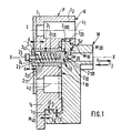
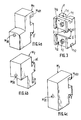
- the jaw holder (P) is made so that it can be used for jaws (M1) for clamping from the inside of a part (not shown) in the drawings) or for jaws (M2) for clamping from the outside of a part.
- the jaw holder (P) comprises a blocking element (1), an assembly (2) for holding the jaws (M1 or M2) in the blocking and locking position, a toothed zone (3), for example on the underside of the element (1) for holding the jaw holder (P) in position on the mandrel (not shown in the drawings) whose main axis is A - A.
- the jaw holder (P) is fixed to the mandrel by screws (41, 42) or the like.
- the element (1) comprises a base (11) and support parts (121) and (122) for the jaw (M1) and the jaw (M2) respectively. These support parts are delimited on the side of the jaw (M1) by a support face (1221) inclined at an angle ( ⁇ ) with a horizontal plane perpendicular (H2) to the vertical plane to the face (110) of said base (11); and on the side of the jaw (M2) by a bearing face (1211) inclined at an angle ( ⁇ ) with a horizontal plane (H1) to said vertical plane (110).
- the assembly (2) essentially comprises a cylindrical jacket in which can move under the action of a spring (22), along the axis x - x, a pusher (21) having a substantially conical front end (210) or having two planes inclined by an angle ( ⁇ ) and ( ⁇ ) respectively.
- a groove (25) can be provided in the pusher (21) in order to be able to maintain it in the locking and locking position or in the unlocking and unlocking position by means of a finger (26) screwed into the fixed element (1 ).
- a (upper) part of said head (210) has an inclined face (2100) of an angle ( ⁇ ) with a horizontal plane (H3) perpendicular to the vertical plane to said face (110 ), and a part (lower) of said head (210) has an inclined face (2101) of an angle ( ⁇ ) with a horizontal plane (H4).
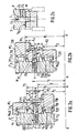
- Each jaw (M1) and (M2) has at one of its ends an inclined face (M21) and (M22) respectively; the angle of inclination of the face (M22) is equal to the angle of inclination ( ⁇ ) of the face (1221) of the element (1), and the angle of inclination of the face (M21 ) is equal to the angle ( ⁇ ) of the face (1211) of the element (1).
- each jaw (M1) and (M2) has a heel (M401) and (M402) respectively which is housed, in the locked position, in one of the recesses (111) and (112) respectively; these recesses are formed diametrically opposite in the periphery of the base (11) of the element (1).
- the horizontal planes (H1, H2, H3, H4) are at distances (R1, R2, r1 and r2) from a horizontal plane passing through the longitudinal axis A - A of the mandrel: R1> r1> r2> R2 .
- the planes (H1 and H2) are at distances (a) and (b) respectively from a horizontal plane passing through the axis x - x, and the planes (H3 and H4) at distances (c) and ( d) respectively of this same horizontal plane passing through the axis x - x.
- the distance (a - c) is therefore equal to (R1 - r1).
- the angle ( ⁇ ) is always greater than the angle ( ⁇ ), and the angle ( ⁇ ) is always greater than the angle ( ⁇ ).
Landscapes
- Engineering & Computer Science (AREA)
- Mechanical Engineering (AREA)
- Gripping On Spindles (AREA)
- Jigs For Machine Tools (AREA)
- Orthopedics, Nursing, And Contraception (AREA)
Applications Claiming Priority (2)
| Application Number | Priority Date | Filing Date | Title |
|---|---|---|---|
| FR8809874 | 1988-07-21 | ||
| FR8809874A FR2634407A1 (fr) | 1988-07-21 | 1988-07-21 | Systeme de changement rapide de mors de serrage sur une machine-outil |
Publications (1)
| Publication Number | Publication Date |
|---|---|
| EP0352162A1 true EP0352162A1 (de) | 1990-01-24 |
Family
ID=9368642
Family Applications (1)
| Application Number | Title | Priority Date | Filing Date |
|---|---|---|---|
| EP89401913A Withdrawn EP0352162A1 (de) | 1988-07-21 | 1989-07-04 | Schnellwechselsystem für Spannklauen auf einer Werkzeugmaschine |
Country Status (4)
| Country | Link |
|---|---|
| US (1) | US4946177A (de) |
| EP (1) | EP0352162A1 (de) |
| JP (2) | JPH02237704A (de) |
| FR (1) | FR2634407A1 (de) |
Cited By (2)
| Publication number | Priority date | Publication date | Assignee | Title |
|---|---|---|---|---|
| WO2012036941A1 (en) * | 2010-09-13 | 2012-03-22 | The Gleason Works | Workholding apparatus for workpiece transfer |
| EP3103574A1 (de) * | 2015-06-08 | 2016-12-14 | Hasan Bahri Atil | Spannsystem zum einspannen von werkstücken, sowie spannfutter und werkzeugmaschine hiermit |
Families Citing this family (12)
| Publication number | Priority date | Publication date | Assignee | Title |
|---|---|---|---|---|
| US5015003A (en) * | 1988-08-03 | 1991-05-14 | Kennametal Inc. | Top jaw assembly with replaceable work holding pads |
| US5735534A (en) * | 1996-11-19 | 1998-04-07 | Edwards; Wayne | Easily replaceable top jaw for a chuck |
| US5899464A (en) * | 1997-06-16 | 1999-05-04 | Northfield Precision Instruments Corporation | Jaw assembly for holding a workpiece |
| US20050218608A1 (en) * | 2002-05-02 | 2005-10-06 | Johann Taglang | Clamping chuck |
| DE10219524A1 (de) * | 2002-05-02 | 2003-11-13 | Roehm Gmbh | Spannfutter |
| DE102005031142A1 (de) * | 2005-07-04 | 2007-01-18 | Forkardt Deutschland Gmbh | Spannvorrichtung, Grundbacken und Aufsatzbacken dafür |
| US7537218B2 (en) * | 2006-07-24 | 2009-05-26 | Wachtler William R | Chuck jaw with adjustable tooth |
| ITTO20100457A1 (it) * | 2010-05-31 | 2011-12-01 | Piermauro Bronzino | Autocentrante per macchine utensili e procedimento per la sua produzione |
| US8292150B2 (en) | 2010-11-02 | 2012-10-23 | Tyco Healthcare Group Lp | Adapter for powered surgical devices |
| JP2012218117A (ja) * | 2011-04-11 | 2012-11-12 | Teikoku Chuck Kk | チャック装置の把持爪取付構造 |
| US9370826B2 (en) * | 2012-10-04 | 2016-06-21 | Adjustable Clamp Company | Rotary chuck for a machine tool |
| CN107717510A (zh) * | 2017-11-16 | 2018-02-23 | 郑州云海信息技术有限公司 | 一种快换结构、夹具及夹具的使用方法 |
Citations (4)
| Publication number | Priority date | Publication date | Assignee | Title |
|---|---|---|---|---|
| FR515283A (fr) * | 1918-05-30 | 1921-03-26 | David Friedmann | Mordache retournable pour plateau de tour |
| DE2218637A1 (de) * | 1972-04-18 | 1973-10-31 | Forkardt Paul Kg | Spannfutter |
| DE2813832A1 (de) * | 1978-03-31 | 1979-10-04 | Berg & Co Gmbh | Backenfutter |
| DE3603459A1 (de) * | 1986-02-05 | 1987-08-06 | Smw Spanneinrichtungen | Einrichtung zur koppelung eines aufsatzspannbackens mit einem grundbacken eines spannfutters |
Family Cites Families (5)
| Publication number | Priority date | Publication date | Assignee | Title |
|---|---|---|---|---|
| DE2533803C3 (de) * | 1975-07-29 | 1983-12-29 | Röhm, Günter Horst, 7927 Sontheim | Kraftbetätigtes Keilspannfutter |
| DE2949613A1 (de) * | 1979-12-10 | 1981-06-11 | SMW Schneider & Weißhaupt GmbH, 7996 Meckenbeuren | Spannfutter fuer drehmaschinen |
| DE3337047C2 (de) * | 1983-10-12 | 1987-03-19 | SMW Schneider & Weißhaupt GmbH, 7996 Meckenbeuren | Einrichtung zur Koppelung einer Aufsatzspannbacke mit einer Grundbacke eines Spannfutters |
| US4667971A (en) * | 1985-06-06 | 1987-05-26 | Buck Chuck Company | Fast change top jaw system |
| FR2584960B1 (fr) * | 1985-07-17 | 1987-10-02 | Sandvik Tobler | Systeme de changement de mors de serrage sur une machine-outil |
-
1988
- 1988-07-21 FR FR8809874A patent/FR2634407A1/fr not_active Withdrawn
-
1989
- 1989-07-04 EP EP89401913A patent/EP0352162A1/de not_active Withdrawn
- 1989-07-14 US US07/380,108 patent/US4946177A/en not_active Expired - Lifetime
- 1989-07-20 JP JP1186178A patent/JPH02237704A/ja active Pending
-
1997
- 1997-09-08 JP JP1997008000U patent/JP2590000Y2/ja not_active Expired - Lifetime
Patent Citations (4)
| Publication number | Priority date | Publication date | Assignee | Title |
|---|---|---|---|---|
| FR515283A (fr) * | 1918-05-30 | 1921-03-26 | David Friedmann | Mordache retournable pour plateau de tour |
| DE2218637A1 (de) * | 1972-04-18 | 1973-10-31 | Forkardt Paul Kg | Spannfutter |
| DE2813832A1 (de) * | 1978-03-31 | 1979-10-04 | Berg & Co Gmbh | Backenfutter |
| DE3603459A1 (de) * | 1986-02-05 | 1987-08-06 | Smw Spanneinrichtungen | Einrichtung zur koppelung eines aufsatzspannbackens mit einem grundbacken eines spannfutters |
Cited By (5)
| Publication number | Priority date | Publication date | Assignee | Title |
|---|---|---|---|---|
| WO2012036941A1 (en) * | 2010-09-13 | 2012-03-22 | The Gleason Works | Workholding apparatus for workpiece transfer |
| CN103124607A (zh) * | 2010-09-13 | 2013-05-29 | 格里森工场 | 用于工件传输的工件保持装置 |
| US8833773B2 (en) | 2010-09-13 | 2014-09-16 | The Gleason Works | Workholding apparatus for workpiece transfer |
| CN103124607B (zh) * | 2010-09-13 | 2015-11-25 | 格里森工场 | 用于工件传输的工件保持装置 |
| EP3103574A1 (de) * | 2015-06-08 | 2016-12-14 | Hasan Bahri Atil | Spannsystem zum einspannen von werkstücken, sowie spannfutter und werkzeugmaschine hiermit |
Also Published As
| Publication number | Publication date |
|---|---|
| FR2634407A1 (fr) | 1990-01-26 |
| JP2590000Y2 (ja) | 1999-02-03 |
| US4946177A (en) | 1990-08-07 |
| JPH02237704A (ja) | 1990-09-20 |
| JPH1079U (ja) | 1998-03-31 |
Similar Documents
| Publication | Publication Date | Title |
|---|---|---|
| EP0352162A1 (de) | Schnellwechselsystem für Spannklauen auf einer Werkzeugmaschine | |
| EP0210083B1 (de) | Schnellwechselsystem für Spannbacken an einer Werkzeugmaschine | |
| EP0274332B1 (de) | Werkzeuggreifer für Handhabungsgeräte, Roboter und dergleichen | |
| EP0308333A1 (de) | Spanneinheit für Werkstücke | |
| EP2043824A2 (de) | Vorrichtung zur schnellen montage von werkzeugen auf einem träger | |
| EP0976482B1 (de) | Zentrier- und Spannvorrichtung, insbesondere für Teile beim Wagenaufbau | |
| EP0824199A1 (de) | Pleuelstange für Brennkraftmaschine | |
| EP0163796A1 (de) | Bohrkopf | |
| EP0063976B1 (de) | Honwerkzeug | |
| EP0362007B1 (de) | Universalspannklotz zum Kopieren von Flachschlüsseln | |
| EP0841114A1 (de) | Spannvorrichtung für Werkzeughalter mit Hohlkonus | |
| EP3848154A1 (de) | Heftklammer mit ausgerichteter klammerzange | |
| FR2518917A1 (fr) | Dispositif de fixation pour outils | |
| FR2651706A1 (fr) | Element de pression pour bridage de pieces a usiner. | |
| EP0045272B1 (de) | Blockiervorrichtung eines Stückes während eines Arbeitsvorganges, wie z.B. Bohren | |
| FR2569596A1 (fr) | Dispositif de bridage et accouplement le comportant | |
| CH685680A5 (fr) | Outil de coupe à plaquettes amovibles. | |
| EP0797718A1 (de) | Provisorischer türanschlag für ein kraftfahrzeugscharnfier und vorrichtung um diesen anzubringen | |
| CH688886A5 (fr) | Etau de serrage modulaire. | |
| EP0234171B1 (de) | Ausdrehkopf | |
| WO1991000391A1 (fr) | Dispositif de fixation elastique d'un rail de chemin de fer sur son support | |
| FR2480166A1 (fr) | Dispositif pour maintenir des cles dans une machine a reproduire les cles | |
| EP1701607A1 (de) | Schneidkopfeinrichtung für buschmäherfahrzeug, rasenkantenschneider oder analog , mit perfektionierten verriegelungsmitteln eines mähfadens | |
| FR2531895A1 (fr) | Cle de serrage | |
| FR2877596A1 (fr) | Perfectionnement aux moyens d'assemblage cone/face entre les organes supports de deux outils rotatifs coaxiaux |
Legal Events
| Date | Code | Title | Description |
|---|---|---|---|
| PUAI | Public reference made under article 153(3) epc to a published international application that has entered the european phase |
Free format text: ORIGINAL CODE: 0009012 |
|
| AK | Designated contracting states |
Kind code of ref document: A1 Designated state(s): CH DE ES GB IT LI SE |
|
| 17P | Request for examination filed |
Effective date: 19900207 |
|
| 17Q | First examination report despatched |
Effective date: 19910131 |
|
| STAA | Information on the status of an ep patent application or granted ep patent |
Free format text: STATUS: THE APPLICATION IS DEEMED TO BE WITHDRAWN |
|
| 18D | Application deemed to be withdrawn |
Effective date: 19920307 |