EP0352400A1 - Röntgengerät - Google Patents
Röntgengerät Download PDFInfo
- Publication number
- EP0352400A1 EP0352400A1 EP89102248A EP89102248A EP0352400A1 EP 0352400 A1 EP0352400 A1 EP 0352400A1 EP 89102248 A EP89102248 A EP 89102248A EP 89102248 A EP89102248 A EP 89102248A EP 0352400 A1 EP0352400 A1 EP 0352400A1
- Authority
- EP
- European Patent Office
- Prior art keywords
- ray
- image
- reference system
- deflection
- television camera
- Prior art date
- Legal status (The legal status is an assumption and is not a legal conclusion. Google has not performed a legal analysis and makes no representation as to the accuracy of the status listed.)
- Granted
Links
- 230000001419 dependent effect Effects 0.000 claims abstract description 3
- 230000006870 function Effects 0.000 claims description 18
- 210000002414 leg Anatomy 0.000 description 2
- 238000010894 electron beam technology Methods 0.000 description 1
- 210000001930 leg bone Anatomy 0.000 description 1
- 210000004417 patella Anatomy 0.000 description 1
- 238000006467 substitution reaction Methods 0.000 description 1
Images



Classifications
-
- A—HUMAN NECESSITIES
- A61—MEDICAL OR VETERINARY SCIENCE; HYGIENE
- A61B—DIAGNOSIS; SURGERY; IDENTIFICATION
- A61B6/00—Apparatus or devices for radiation diagnosis; Apparatus or devices for radiation diagnosis combined with radiation therapy equipment
- A61B6/44—Constructional features of apparatus for radiation diagnosis
- A61B6/4429—Constructional features of apparatus for radiation diagnosis related to the mounting of source units and detector units
- A61B6/4435—Constructional features of apparatus for radiation diagnosis related to the mounting of source units and detector units the source unit and the detector unit being coupled by a rigid structure
- A61B6/4441—Constructional features of apparatus for radiation diagnosis related to the mounting of source units and detector units the source unit and the detector unit being coupled by a rigid structure the rigid structure being a C-arm or U-arm
-
- A—HUMAN NECESSITIES
- A61—MEDICAL OR VETERINARY SCIENCE; HYGIENE
- A61B—DIAGNOSIS; SURGERY; IDENTIFICATION
- A61B6/00—Apparatus or devices for radiation diagnosis; Apparatus or devices for radiation diagnosis combined with radiation therapy equipment
- A61B6/42—Arrangements for detecting radiation specially adapted for radiation diagnosis
- A61B6/4208—Arrangements for detecting radiation specially adapted for radiation diagnosis characterised by using a particular type of detector
- A61B6/4225—Arrangements for detecting radiation specially adapted for radiation diagnosis characterised by using a particular type of detector using image intensifiers
-
- H—ELECTRICITY
- H04—ELECTRIC COMMUNICATION TECHNIQUE
- H04N—PICTORIAL COMMUNICATION, e.g. TELEVISION
- H04N5/00—Details of television systems
- H04N5/30—Transforming light or analogous information into electric information
- H04N5/32—Transforming X-rays
-
- H—ELECTRICITY
- H05—ELECTRIC TECHNIQUES NOT OTHERWISE PROVIDED FOR
- H05G—X-RAY TECHNIQUE
- H05G1/00—X-ray apparatus involving X-ray tubes; Circuits therefor
- H05G1/08—Electrical details
- H05G1/26—Measuring, controlling or protecting
-
- A—HUMAN NECESSITIES
- A61—MEDICAL OR VETERINARY SCIENCE; HYGIENE
- A61B—DIAGNOSIS; SURGERY; IDENTIFICATION
- A61B6/00—Apparatus or devices for radiation diagnosis; Apparatus or devices for radiation diagnosis combined with radiation therapy equipment
- A61B6/44—Constructional features of apparatus for radiation diagnosis
- A61B6/4405—Constructional features of apparatus for radiation diagnosis the apparatus being movable or portable, e.g. handheld or mounted on a trolley
-
- A—HUMAN NECESSITIES
- A61—MEDICAL OR VETERINARY SCIENCE; HYGIENE
- A61B—DIAGNOSIS; SURGERY; IDENTIFICATION
- A61B6/00—Apparatus or devices for radiation diagnosis; Apparatus or devices for radiation diagnosis combined with radiation therapy equipment
- A61B6/44—Constructional features of apparatus for radiation diagnosis
- A61B6/4429—Constructional features of apparatus for radiation diagnosis related to the mounting of source units and detector units
- A61B6/4458—Constructional features of apparatus for radiation diagnosis related to the mounting of source units and detector units the source unit or the detector unit being attached to robotic arms
Definitions
- the invention relates to an x-ray device for creating x-ray images with an adjustable x-ray tube, a patient couch and an adjustable image recording system as system components, which has an image intensifier and a television camera coupled to it, with a control device for the system components and an image display system.
- DE-OS 3 536 079 describes an X-ray diagnostic device in which the system components, the X-ray tube, the patient bed and the image recording system are attached to robot arms so that they can be freely moved in three dimensions.
- the problem arises that the television camera of the image recording system is oriented as desired, so that the orientation of the x-ray image can no longer be assigned to the circumstances.
- it is important for the doctor that the image displayed on the monitor is reproduced, for example, in a position that the viewer expects due to its position in relation to the patient.
- robot devices with a wide range of projection possibilities the correction of the device rotation around the axis of the central beam is of great importance.
- the invention is based on the object of effecting electronic compensation and correction of the device rotation about the axis of the central beam in an X-ray device of the type mentioned at the outset, so that the X-ray image has a desired orientation.
- the object is achieved in that means for detecting the position of a reference system and computing means connected to the means are provided which are angle-dependent Determine the superimposition of the deflection voltages and are connected to deflection stages for the television camera in such a way that the target of the television camera is scanned independently of the rotation of the image recording device in the orientation of the reference system. It is thereby achieved that the position of the reference system is recognized by the means. This position is evaluated by the computer and the horizontal and vertical deflection voltages are superimposed, so that the deflection of the television camera always takes place in such a way that the scanning direction is perpendicular to the desired position of the x-ray image, for example the alignment of the reference system.
- a corresponding correction can be carried out automatically if position sensors are arranged on at least one of the system components, which detect the angle of rotation of the image recording system with respect to the reference system, and if the computer is connected to the position sensors.
- the position sensor which, for example, only has to be connected to the image recording system when the reference system is rigidly assigned, enables the computer to determine the angle of rotation of the image recording system for aligning the reference system, for example the patient bed.
- a simple reference system is obtained when it is the patient bed.
- a reproduction of the x-ray image in the position in which the examinee expects it based on his position to the patient can be achieved if the reference system is the orientation of an examinee to the x-ray system, if an input device for a position of the examinee is connected to the computer and if the computer is designed such that the angle between the position and the deflection unit of the television camera with respect to the central beam of the X-ray tube is determined.
- An advantageous design of the computer is obtained if it has a first stage in which the positions of the positions tion encoder the angle is determined if the sine and cosine functions corresponding to this angle are determined in a second stage connected to it, if multiplication stages are connected to this second stage, the second inputs of which are connected to the respective sawtooth generators, and if the output signals are connected in downstream addition stages of two multiplication stages are combined, the output signals of which are fed to the deflection stages, the sawtooth corresponding to the deflection stage being multiplied by the cosine function and the sawtooth not corresponding to the deflection stage being multiplied by the sine function.
- Any adjustment of the x-ray image can also be achieved with a movable x-ray device if means are arranged between the television camera and the image display system that cause marks to be superimposed as a reference system in the x-ray image depicted on the image display system if adjustment means for the position of the marks are connected to the means and if the funds are connected to the computer.
- Any arbitrary setting can be made if the means are designed such that two marks are superimposed on the x-ray image, the first mark identifying the reference system and the second mark identifying the position of the reference system. The setting is simplified if the means are designed in such a way that a mark is superimposed on the x-ray image which identifies the desired position, the vertical on the image display system being the reference system.
- the X-ray tube 1 shows an X-ray device with an X-ray tube 1, an image recording system with an X-ray image intensifier 2 and a television camera 3, and a monitor 4 as an image display system.
- the X-ray tube 1 and the image recording system 2 and 3 are connected to one another by a so-called C-arm 5. However, they can also be hung separately by robotic arms.
- the C-arm 5 is rotatably and pivotably connected to a holder 6 by a robot arm.
- the robot arm has a first lever 7 which is attached to the holder 6 so as to be rotatable and pivotable, and which is pivotally connected at its free end to a second lever 8 to which the C-arm 5 is fastened in a pivotable and pivotable manner.
- a patient couch 9 on which the patient 30 can lie is arranged between the X-ray tube 1 and the X-ray image intensifier 2.
- the patient couch 9 has a fixed, non-changeable orientation to the holder 6. However, this is not absolutely necessary. As already mentioned, it can also be kept freely movable by robot arms. In this case, the angle of rotation of the patient bed 9 would also be determined by position sensors.
- Position sensors 10 are attached to the joints of the robot arm and are connected to a computer 11 via a first line 31.
- the computer 11 has a first stage 12 which determines the angle of rotation alpha from the position of the position transmitter 10.
- a second stage 13 connected to this, the corresponding sine and cosine functions sin ⁇ , -sin ⁇ and cos ⁇ are formed from these values of the angle alpha ( ⁇ ).
- These functions sin ⁇ , -sin ⁇ and cos ⁇ are supplied to four multiplication stages 14 to 17, in which the off output signals of the generator 18 for the horizontal sawtooth voltage with the two functions sin ⁇ and cos ⁇ and the output signals of the generator 19 for the vertical sawtooth voltage with both functions -sin ⁇ and cos ⁇ are multiplied.
- the outputs of two of the multiplication stages 14 to 17 are combined in addition stages 20 and 21 and superimposed.
- the horizontal deflection stage 22 is connected to the addition stage 20 and the vertical deflection stage 23 is connected to the addition stage 21. Both deflection stages 22 and 23 are connected to the deflection set of the television camera 3.
- the addition stage 20 which generates an output signal Ah supplied to the horizontal deflection stage 22, is supplied with the output signal of the first multiplication stage 14, which corresponds to the multiplication of the horizontal sawtooth voltage Sh by the function cos ⁇ .
- the product of the vertical sawtooth voltage Sv with the function -sin ⁇ is taken as the output signal from the second multiplication stage 15.
- the horizontal sawtooth voltage Sh is multiplied by the function sin ⁇
- the fourth multiplication stage 17 forms a product of the vertical sawtooth voltage Sv with the cosine function.
- the respective deflection stages 22 and 23 are supplied with the corresponding sawtooth voltage multiplied by the cosine function and the other sawtooth voltage multiplied by the sine function.
- the scanning system of the television camera 3 can, as is generally customary, be magnetic, so that deflection coils generate a corresponding deflection field.
- the deflection can also, as shown in FIG. 2, take place electrostatically, the corresponding deflection voltages Ah and Av of the deflection stages 22 and 23 being applied to the respective deflection plates 24 to 27.
- the first square 28 indicates the usual grid position when the on the baffles 24 to 27 sawtooth voltage S is applied. If, on the other hand, a deflection is to take place which is rotated by the angle alpha with respect to the first square 28, then a deflection must take place within the second square 29.
- the deflection voltages A now used must deflect the electron beam of the television camera 3, which lies perpendicular to the side lengths of this second square 29.
- Any point P1 with the right-angled coordinates h1 and v1 and the angular coordinates r, ⁇ 1 should be rotated by P2 with the right-angled coordinates h2 and v2 and the angular coordinates r, ⁇ 2 on a circular arc with the radius r by the angle ⁇ (FIG. 3) .
- the patient couch 9 was chosen as the reference system, so that the angle alpha between the alignment of the patient couch 9 and the alignment of the vertical deflection of the television camera 3 was to be determined. This was done via the position transmitter 10.
- the computer 11 was also supplied with the position of the C-arm 5 via a second line 32, regardless of whether the system was operating in under-table or over-table mode. The computer 11 then determined the corresponding functions from these values.
- an input device 34 is connected to the computer 11, via which the position of the examiner 33 is transmitted to the first stage 12. After entering the position, for example as coordinates via a keyboard 35, the first stage 12 of the computer 11 determines the connection between the position and the central beam of the X-ray tube 1 and then determines the angle alpha between this connection and the respective orientation on the basis of the positions of the position sensors 10 of the X-ray machine.
- This arrangement according to the invention provides an X-ray device in which an automatic, electronic correction of the device rotation takes place, so that the X-ray image reproduced on the monitor 4 always has the required, desired orientation.
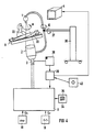
- FIG. 4 shows a further embodiment for a movable, movable x-ray device 36, which essentially corresponds to that shown in FIG. 1.
- the same parts were given the same reference numerals.
- an image memory 38 for the x-ray images and a fade-in device 39 are connected, which, as will be explained later, fade marks into the television image. These marks can be changed in their position by adjusting means 40.
- Either the setting means 40 or, as shown, the fade-in device 39 are connected to the computer 11, which feed the position of the marks to it, so that, as described with reference to FIG. 1, it determines the necessary deflection voltages for the television camera 3.
- FIGS. 5 to 8 X-ray images of a human leg 40 with the leg bones 41 and 42 and the knee cap 43 are shown in all the figures.
- FIG. 5 shows the initial image in the basic position without rotation of the X-ray image, as it was read into the image memory 38 after a first recording, for example.
- a first mark 45 is set by the setting means 40 to a prominent position in the x-ray image, for example to the leg 41, so that this first mark 45 can be evaluated as a reference system.
- a second mark 46 is now adjusted such that its position indicates the desired position of the reference system. From the angle that the two marks 45 and 46 form with one another, the computer 11 determines the required deflection, so that when the x-ray device 36 is switched on again, the x-ray image shown on the image display 4 is in the desired position, as shown with reference to FIG. 6 is.
- only one mark 47 can be used if, for example, the vertical orientation in the x-ray image is selected as the reference system.
- the computer 11 determines the angle of the mark 47 with respect to the reference direction and from this the required deflection, so that here again after switching on the x-ray system, the image in FIG 8 has the desired orientation shown.
- an X-ray device is obtained in which any electrode correction of the device rotation can take place, so that the X-ray image lies on the monitor 4 in its desired orientation, which is influenced by the setting means 40.
Landscapes
- Health & Medical Sciences (AREA)
- Life Sciences & Earth Sciences (AREA)
- Engineering & Computer Science (AREA)
- Medical Informatics (AREA)
- General Health & Medical Sciences (AREA)
- Heart & Thoracic Surgery (AREA)
- Biophysics (AREA)
- Nuclear Medicine, Radiotherapy & Molecular Imaging (AREA)
- Optics & Photonics (AREA)
- Pathology (AREA)
- Radiology & Medical Imaging (AREA)
- Biomedical Technology (AREA)
- Physics & Mathematics (AREA)
- Molecular Biology (AREA)
- Surgery (AREA)
- Animal Behavior & Ethology (AREA)
- High Energy & Nuclear Physics (AREA)
- Public Health (AREA)
- Veterinary Medicine (AREA)
- Toxicology (AREA)
- Multimedia (AREA)
- Signal Processing (AREA)
- Apparatus For Radiation Diagnosis (AREA)
- Analysing Materials By The Use Of Radiation (AREA)
- X-Ray Techniques (AREA)
- Transforming Light Signals Into Electric Signals (AREA)
- Closed-Circuit Television Systems (AREA)
Abstract
Description
- Die Erfindung betrifft ein Röntgengerät zur Erstellung von Röntgenbildern mit einer verstellbaren Röntgenröhre, einer Patientenliege und einem verstellbaren Bildaufnahmesystem als Anlagekomponenten, das einen Bildverstärker und eine daran angekoppelte Fernsehkamera aufweist, mit einer Steuervorrichtung für die Anlagekomponenten und einem Bildwiedergabesystem.
- In der DE-OS 3 536 079 ist eine Röntgendiagnostikeinrichtung beschrieben, bei der die Anlagekomponenten, die Röntgenröhre, die Patientenliege und das Bildaufnahmesystem an Roboterarmen angebracht sind, so daß sie sich dreidimensional frei beweglich verstellen lassen. Dadurch tritt aber das Problem auf, daß die Fernsehkamera des Bildaufnahmesystems beliebig ausgerichtet ist, so daß eine Zuordnung der Ausrichtung des Röntgenbildes zu den Gegebenheiten nicht mehr erfolgen kann. Dabei ist es aber für den Arzt wichtig, daß das am Monitor dargestellte Bild beispielsweise in einer Lage wiedergegeben wird, die er als Betrachter auf Grund seiner Position zum Patienten erwartet. Bei den Robotgeräten mit mannigfaltigen Projektionsmöglichkeiten kommt der Korrektur der Gerätedrehung um die Achse des Zentralstrahles somit eine große Bedeutung zu.
- Die Erfindung geht von der Aufgabe aus, bei einem Röntgengerät der eingangs genannten Art einen elektronischen Ausgleich und eine Korrektur der Gerätedrehung um die Achse des Zentralstrahles zu bewirken, so daß das Röntgenbild eine gewünschte Ausrichtung aufweist.
- Die Aufgabe wird erfindungsgemäß dadurch gelöst, daß Mittel zur Erfassung der Lage eines Bezugssystems und mit den Mitteln verbunde Rechenmittel vorgesehen sind, die eine winkelabhängige Überlagerung der Ablenkspannungen ermitteln und mit Ablenkstufen für die Fernsehkamera derart verbunden sind, daß eine Abtastung des Targets der Fernsehkamera unabhängig von der Drehung der Bildaufnahmevorrichtung in Ausrichtung des Bezugssystems erfolgt. Dadurch wird erreicht, daß durch die Mittel die Lage des Bezugssystems erkannt wird. Durch den Rechner erfolgt eine Auswertung dieser Lage und eine Überlagerung der Horizontal- und Vertikalablenkspannungen, so daß die Ablenkung der Fernsehkamera immer derart erfolgt, daß die Abtastrichtung senkrecht auf der gewünschten Lage des Röntgenbildes, beispielsweise auf der Ausrichtung des Bezugssystems, erfolgt.
- Bei feststehendem Röntgengerät kann eine entsprechende Korrektur automatisch erfolgen, wenn an wenigstens einer der Anlagekomponenten Positionsgeber angeordnet sind, die den Drehwinkel des Bildaufnahmesystems zu dem Bezugssystem erfassen, und wenn an die Positionsgeber der Rechner angeschlossen ist. Durch die Positionsgeber, die beispielsweise bei starrer Zuordnung des Bezugssystems nur an dem Bildaufnahmesystem angeschlossen sein müssen, ermittelt der Rechner den Drehwinkel des Bildaufnahmesystems zur Ausrichtung des Bezugssystems, beispielsweise der Patientenliege.
- Ein einfaches Bezugssystem erhält man, wenn es die Patientenliege ist. Eine Wiedergabe des Röntgenbildes in der Lage, in der die Untersuchungsperson auf Grund ihrer Position zum Patienten es erwartet, kann erreicht werden, wenn das Bezugssystem die Ausrichtung einer Untersuchungsperson zur Röntgenanlage ist, wenn eine Eingabevorrichtung für eine Position der Untersuchungsperson mit dem Rechner verbunden ist und wenn der Rechner derart ausgebildet ist, daß der Winkel zwischen der Position und der Ablenkeinheit der Fernsehkamera in Bezug auf den Zentralstrahl der Röntgenröhre ermittelt wird.
- Eine vorteilhafte Ausbildung des Rechners erhält man, wenn er eine erste Stufe aufweist, in der aus den Stellungen der Posi tionsgeber der Winkel bestimmt wird, wenn in einer daran angeschlossenen zweiten Stufe die diesem Winkel entsprechenden Sinus- und Kosinusfunktionen ermittelt werden, wenn an dieser zweiten Stufe Multiplikatinsstufen angeschlossen sind, deren zweite Eingänge mit den jeweiligen Sägezahngeneratoren verbunden sind, und wenn in nachgeschalteten Additionsstufen die Ausgangssignale von jeweils zwei Multiplikationsstufen zusammengefaßt werden, deren Ausgangssignale den Ablenkstufen zugeführt werden, wobei der der Ablenkstufe entsprechende Sägezahn mit der Kosinusfunktion und der der Ablenkstufe nicht entsprechende Sägezahn mit der Sinusfunktion multipliziert wird.
- Eine beliebige Einstellung des Röntgenbildes läßt sich auch bei einem verfahrbaren Röntgengerät erreichen, wenn zwischen Fernsehkamera und Bildwiedergabesystem Mittel angeordnet sind, die eine Einblendung von Marken als Bezugssystem in das auf dem Bildwiedergabesystem abgebildete Röntgenbild bewirken, wenn Einstellmittel für die Lage der Marken mit den Mittel verbunden sind und wenn die Mittel an dem Rechner angeschlossen sind. Eine beliebige, freiwählbare Einstellung kann erfolgen, wenn die Mittel derart ausgebildet sind, daß zwei Marken in das Röntgenbild eingeblendet werden, wobei die erste Marke das Bezugssystem und die zweite Marke die Lage des Bezugssystems kennzeichnet. Die Einstellung vereinfacht sich, wenn die Mittel derart ausgebildet sind, daß eine Marke in das Röntgenbild eingeblendet wird, die die gewünschte Lage kennzeichnet, wobei die Senkrechte auf dem Bildwiedergabesystem das Bezugssystem ist.
- Die Erfindung ist nachfolgend anhand eines in der Zeichnung dargestellten Ausführungsbeispieles näher erläutert. Es zeigen:
- FIG 1 ein schematisch dargestelltes Röntgengerät mit einem erfindungsgemäßen Rechner,
- FIG 2 und 3 die geometrischen Verhältnisse bei der Abtastung,
- FIG 4 eine weitere erfindungsgemäße Ausführungsform des Röntgengerates und
- FIG 5 bis 8 Beispiele zur wahlweisen Einstellung der Bilddrehung.
- In der FIG 1 ist ein Röntgengerät mit einer Röntgenröhre 1, einem Bildaufnahmesystem mit einem Röntgenbildverstärker 2 und einer Fernsehkamera 3 und als Bildwiedergabesystem einem Monitor 4 dargestellt. Die Röntgenröhre 1 und das Bildaufnahmesystem 2 und 3 sind durch einen sogenannten C-Bogen 5 miteinander verbunden. Sie können aber auch durch Roboterarme getrennt aufgehängt sein. Der C-Bogen 5 ist durch einen Roboterarm mit einer Halterung 6 dreh- und schwenkbar verbunden. Der Roboterarm weist dabei einen an der Halterung 6 dreh- und schwenkbar angebrachten ersten Hebel 7 auf, der an seinem freien Ende mit einem zweiten Hebel 8 schwenkbar verbunden ist, an dem der C-Bogen 5 dreh- und schwenkbar befestigt ist. Zwischen Röntgenröhre 1 und Röntgenbildverstärker 2 ist eine Patientenliege 9 angeordnet, auf der der Patient 30 liegen kann. Der Einfachheit halber sei angenommen, daß die Patientenliege 9 eine feste, nicht veränderliche Ausrichtung zur Halterung 6 aufweist. Dies ist aber nicht unbedingt erforderlich. Sie kann auch, wie bereits erwähnt, von Roboterarmen frei beweglich gehalten werden. In diesem Falle wäre der Drehwinkel der Patientenliege 9 ebenfalls durch Positionsgeber zu ermitteln.
- An den Gelenken des Robotorarms sind Positionsgeber 10 angebracht, die über eine erste Leitung 31 mit einem Rechner 11 verbunden sind. Der Rechner 11 weist dabei eine erste Stufe 12 auf, die aus der Stellung der Positionsgeber 10 den Drehwinkel Alpha ermittelt. In einer daran angeschlossenen zweiten Stufe 13 werden aus diesen Werten des Winkels Alpha (α) die entsprechenden Sinus- und Kosinus-Funktionen sinα, -sinα und cosα gebildet. Diese Funktionen sinα, -sinα und cosα werden vier Multiplikationsstufen 14 bis 17 zugeführt, in denen die Aus gangssignale des Generators 18 für die horizontale Sägezahnspannung mit den beiden Funktionen sinα und cosα und die Ausgangssignale des Generators 19 für die vertikale Sägezahnspannung mit beiden Funktionen -sinα und cosα multipliziert werden. Die Ausgänge von jeweils zwei der Multiplikationsstufen 14 bis 17 werden in Additionsstufen 20 und 21 zusammengefaßt und überlagert. An der Additionsstufe 20 ist die horizontale Ablenkstufe 22 und an die Additionsstufe 21 die vertikale Ablenkstufe 23 angeschlossen. Beide Ablenkstufen 22 und 23 sind mit dem Ablenksatz der Fernsehkamera 3 verbunden.
- Der Additionsstufe 20, die ein der horizontalen Ablenkstufe 22 zugeführtes Ausgangssignal Ah erzeugt, wird das Ausgangssignal der ersten Multiplikationsstufe 14 zugeführt, das der Multiplikation der horizontalen Sägezahnspannung Sh mit der Funktion cosα entspricht. Der zweiten Multiplikationsstufe 15 wird als Ausgangssignal das Produkt der vertikalen Sägezahnspannung Sv mit der Funktion -sinα entnommen. In der dritten Multiplikationsstufe 16 wird die horizontale Sägezahnspannung Sh mit der Funktion sinα multipliziert, während die vierte Multiplikationsstufe 17 ein Produkt der vertikalen Sägezahnspannung Sv mit der Kosinusfunktion bildet. Das bedeutet aber, daß den jeweiligen Ablenkstufen 22 und 23 die mit der Kosinus-Funktion multiplizierte entsprechende Sägezahnspannung und die mit der Sinus-Funktion multiplizierte andere Sägezahnspannung zugeführt wird.
- Anhand der FIG 2 werden nun die geometrischen Verhältnisse bei der Abtastung näher erläutert. Das Abtastsystem der Fernsehkamera 3 kann, wie allgemein üblich, magnetisch sein, so daß Ablenkspulen ein entsprechendes Ablenkfeld erzeugen. Die Ablenkung kann aber auch, wie in FIG 2 dargestellt, elektrostatisch erfolgen, wobei an die jeweiligen Ablenkplatten 24 bis 27 die entsprechenden Ablenkspannungen Ah und Av der Ablenkstufen 22 und 23 angelegt werden. Das erste Quadrat 28 gibt dabei die übliche Rasterlage an, wenn an den Ablenkplatten 24 bis 27 die jeweilige Sägezahnspannung S angelegt wird. Soll dagegen eine Ablenkung erfolgen, die gegenüber dem ersten Quadrat 28 um den Winkel Alpha verdreht ist, so muß eine Ablenkung innerhalb des zweiten Quadrates 29 erfolgen. Die nun gebrauchten Ablenkspannungen A müssen eine Ablenkung des Elektronenstrahles der Fernsehkamera 3 bewirken, die senkrecht auf den Seitenlängen dieses zweiten Quadrates 29 liegt. Diese erforderlichen Ablenkspannungen Ah und Av für einen beliebigen Drehwinkelα lassen sich wie folgt mathematisch ermitteln:
- Ein beliebiger Punkt P1 mit den rechtwinkligen Koordinaten h1 und v1 und den Winkelkoordinaten r, φ1 soll nach P2 mit den rechtwinkligen Koordinaten h2 und v2 und den Winkelkoordinaten r, φ2 auf einem Kreisbogen mit dem Radius r um den Winkel α gedreht werden (FIG 3).
Es gilt nun: h1 = r·cosφ1 (1)
h2 = r·cosφ2 (2)
v1 = r·cosφ1 (3)
v2 = r·cosφ2 (4)
Mit φ2 = φ1 + α wird:
h2 = r cos (φ1 + α)
v2 = r sin (φ1 + α)
Für die Addition zweier Winkel gilt:
cos = (φ + α) = cosφ · cosα - sinφ ·sinα
sin = (φ + α) = sinφ · cosα +cosφ ·sinα
und somit:
h2 = r cosφ1 ·cosα - r sinφ1 · sinα
v2 = r sinφ1 ·cosα + r cosφ1 · sinα
Substitution mit (1) und (3) ergibt:
h2 = h1 cos α - v1 sinα
v2 = v1 cos α - h1 sinα
- Da der Punkt P1 einen beliebigen Punkt im Quadrat 28 darstellt und gemäß dem Fernsehraster abgelenkt werden darf, ergeben sich die allgemeinen Ablenkfunktionen für die Ablenkspannungen des Quadrates 29:
Ah = cosα Sh - sinα Sv
Av = cosα Sv + sinα Sh. - Im bisherigen Falle wurde die Patientenliege 9 als Bezugssystem gewählt, so daß der Winkel Alpha zwischen der Ausrichtung der Patientenliege 9 und der Ausrichtung der vertikalen Ablenkung der Fernsehkamera 3 zu bestimmen war. Dies erfolgte über die Positionsgeber 10. Dem Rechner 11 wurde weiterhin über eine zweite Leitung 32 die Stellung des C-Bogens 5 zugeführt, ob die Anlage im Untertisch- oder Obertischbetrieb arbeitete. Aus diesen Werten ermittelte der Rechner 11 dann die entsprechenden Funktionen.
- In manchen Fällen kann es aber vorteilhaft sein, daß nicht die Patientenliege 9 das Bezugssystem ist, sondern die Blickrichtung einer Untersuchungsperson 33 auf den Patienten 30 und so mit auf den Zentralstrahl der Röntgenröhre 1. Hierzu ist am Rechner 11 eine Eingabevorrichtung 34 angeschlossen, über die der ersten Stufe 12 die Position der Untersuchungsperson 33 übermittelt wird. Nach Eingabe der Position beispielsweise als Koordinaten über eine Tastatur 35 ermittelt die erste Stufe 12 des Rechners 11 die Verbindung zwischen der Position und des Zentralstrahles der Rontgenröhre 1 und bestimmt dann auf Grund der Stellungen der Positionsgeber 10 den Winkel Alpha zwischen dieser Verbindung und der jeweiligen Ausrichtung des Röntgengerates.
- Durch diese erfindungsgemäße Anordnung erhält man ein Röntgengerät, bei dem eine automatische, elektronische Korrektur der Gerätedrehung erfolgt, so daß das auf dem Monitor 4 wiedergegebene Röntgenbild immer die erforderliche, gewünschte Ausrichtung aufweist.
- In der FIG 4 ist eine weitere Ausführungsform für ein verfahrbares, bewegliches Röntgengerät 36 dargestellt, das im wesentlichen dem in FIG 1 dargestellten entspricht. Dabei wurden gleiche Teile mit gleichen Bezugszeichen versehen. An dem Röntgengerät 36 ist über einen Tragarm 37 der C-Bogen 5 befestigt, der die Röntgenröhre 1 und den Röntgenbildverstärker 2 mit Fernsehkamera 3 hält. In die in FIG 1 nicht dargestellte Verbindung zwischen der Fernsehkamera 3 und dem Monitor 4 ist ein Bildspeicher 38 für die Röntgenbilder und eine Einblendvorrichtung 39 geschaltet, die, wie noch erklärt wird, Marken in das Fernsehbild einblendet. Diese Marken lassen sich durch Einstellmittel 40 in ihrer Lage verändern. Entweder die Einstellmittel 40 oder, wie dargestellt, die Einblendvorrichtung 39 sind mit dem Rechner 11 verbunden, die die Lage der Marken ihm zuführen, so daß er, wie anhand der FIG 1 beschrieben, daraus die erforderlichen Ablenkspannungen für die Fernsehkamera 3 ermitteln.
- Anhand der FIG 5 bis 8 werden nun Beispiele zu dieser zweiten erfindungsgemäßen Ausführungsform näher erläutert. In allen Figuren sind Röntgenbilder eines menschlichen Beines 40 mit den Beinknochen 41 und 42 und der Kniescheibe 43 dargestellt.
- FIG 5 zeigt dabei das Ausgangsbild in der Grundstellung ohne Drehung des Röntgenbildes, wie es beispielsweise nach einer ersten Aufnahme in den Bildspeicher 38 eingelesen wurde. Durch die Einstellmittel 40 wird eine erste Marke 45 auf eine markante Stelle im Röntgenbild, beispielsweise auf das Bein 41, eingestellt, so daß diese erste Marke 45 als Bezugssystem gewertet werden kann. Eine zweite Marke 46 wird nun derart verstellt, daß ihre Lage die gewünschte Lage des Bezugssystemes angibt. Aus dem Winkel, den die beiden Marken 45 und 46 miteinander bilden, ermittelt der Rechner 11 die erforderliche Ablenkung, so daß bei erneutem Einschalten des Röntgengerätes 36 das auf der Bildwiedergabe 4 dargestellte Röntgenbild sich in der gewünschten Lage befindet, wie dies anhand FIG 6 gezeigt ist.
- Anstelle von zwei Marken läßt sich nur eine Marke 47 verwenden, wenn als Bezugssystem beispielsweise die senkrechte Ausrichtung im Röntgenbild gewählt wird. Durch die Wahl der Marke 47, die wiederum durch die Einstellmittel 40 in ihrer Lage veränderbar ist, ermittelt der Rechner 11 den Winkel der Marke 47 zu der Bezugsrichtung und daraus die erforderliche Ablenkung, so daß auch hier wieder nach Einschalten der Röntgenanlage das Bild die in FIG 8 dargestellte gewünschte Ausrichtung aufweist.
- Durch diese zweite erfindungsgemäße Anordnung erhält man ein Röntgengerät, bei dem eine beliebige elektrodische Korrektur der Gerätedrehung erfolgen kann, so daß auf dem Monitor 4 das Röntgenbild in seiner gewünschten, durch die Einstellmittel 40 beeinflußten Ausrichtung liegt.
Claims (9)
Applications Claiming Priority (2)
| Application Number | Priority Date | Filing Date | Title |
|---|---|---|---|
| DE3825709 | 1988-07-28 | ||
| DE3825709 | 1988-07-28 |
Publications (2)
| Publication Number | Publication Date |
|---|---|
| EP0352400A1 true EP0352400A1 (de) | 1990-01-31 |
| EP0352400B1 EP0352400B1 (de) | 1993-04-28 |
Family
ID=6359788
Family Applications (1)
| Application Number | Title | Priority Date | Filing Date |
|---|---|---|---|
| EP89102248A Expired - Lifetime EP0352400B1 (de) | 1988-07-28 | 1989-02-09 | Röntgengerät |
Country Status (4)
| Country | Link |
|---|---|
| US (1) | US4937848A (de) |
| EP (1) | EP0352400B1 (de) |
| JP (1) | JPH0254154A (de) |
| DE (1) | DE58904181D1 (de) |
Cited By (1)
| Publication number | Priority date | Publication date | Assignee | Title |
|---|---|---|---|---|
| WO2004056088A1 (de) * | 2002-12-18 | 2004-07-01 | Siemens Aktiengesellschaft | Kamerasystem mit bilddrehung, insbesondere für medizinische anwendungen |
Families Citing this family (5)
| Publication number | Priority date | Publication date | Assignee | Title |
|---|---|---|---|---|
| US5077769A (en) * | 1990-06-29 | 1991-12-31 | Siemens Gammasonics, Inc. | Device for aiding a radiologist during percutaneous transluminal coronary angioplasty |
| US5457728A (en) * | 1990-11-14 | 1995-10-10 | Cedars-Sinai Medical Center | Coronary tracking display |
| US5493597A (en) * | 1993-09-10 | 1996-02-20 | Kabushiki Kaisha Toshiba | X-ray diagnostic apparatus and X-ray diagnostic method |
| FR2786387B1 (fr) * | 1998-11-27 | 2001-01-26 | Ge Medical Syst Sa | Dispositif et procede de prise d'images radiologiques |
| US6947585B1 (en) * | 2000-08-28 | 2005-09-20 | Cti Pet Systems, Inc. | On-line correction of patient motion in three-dimensional positron emission tomography |
Citations (4)
| Publication number | Priority date | Publication date | Assignee | Title |
|---|---|---|---|---|
| DE2108657A1 (de) * | 1970-02-25 | 1971-09-30 | Gustavsson L | Maß- und Lagebestimmung |
| FR2194402A1 (de) * | 1972-08-05 | 1974-03-01 | Radiologie Cie Gle | |
| US4207595A (en) * | 1977-04-28 | 1980-06-10 | U.S. Philips Corporation | Apparatus for making laminar radiograms |
| EP0220501A1 (de) * | 1985-10-09 | 1987-05-06 | Siemens Aktiengesellschaft | Röntgendiagnostikanlage mit durch eine Steuervorrichtung verstellbaren Anlagenkomponenten |
Family Cites Families (1)
| Publication number | Priority date | Publication date | Assignee | Title |
|---|---|---|---|---|
| US4674107A (en) * | 1985-07-31 | 1987-06-16 | Picker International, Inc. | Display for radiation imaging |
-
1989
- 1989-02-09 DE DE8989102248T patent/DE58904181D1/de not_active Expired - Fee Related
- 1989-02-09 EP EP89102248A patent/EP0352400B1/de not_active Expired - Lifetime
- 1989-02-21 JP JP1041480A patent/JPH0254154A/ja active Pending
- 1989-04-27 US US07/343,739 patent/US4937848A/en not_active Expired - Fee Related
Patent Citations (4)
| Publication number | Priority date | Publication date | Assignee | Title |
|---|---|---|---|---|
| DE2108657A1 (de) * | 1970-02-25 | 1971-09-30 | Gustavsson L | Maß- und Lagebestimmung |
| FR2194402A1 (de) * | 1972-08-05 | 1974-03-01 | Radiologie Cie Gle | |
| US4207595A (en) * | 1977-04-28 | 1980-06-10 | U.S. Philips Corporation | Apparatus for making laminar radiograms |
| EP0220501A1 (de) * | 1985-10-09 | 1987-05-06 | Siemens Aktiengesellschaft | Röntgendiagnostikanlage mit durch eine Steuervorrichtung verstellbaren Anlagenkomponenten |
Cited By (1)
| Publication number | Priority date | Publication date | Assignee | Title |
|---|---|---|---|---|
| WO2004056088A1 (de) * | 2002-12-18 | 2004-07-01 | Siemens Aktiengesellschaft | Kamerasystem mit bilddrehung, insbesondere für medizinische anwendungen |
Also Published As
| Publication number | Publication date |
|---|---|
| EP0352400B1 (de) | 1993-04-28 |
| US4937848A (en) | 1990-06-26 |
| JPH0254154A (ja) | 1990-02-23 |
| DE58904181D1 (de) | 1993-06-03 |
Similar Documents
| Publication | Publication Date | Title |
|---|---|---|
| DE68916287T2 (de) | Röntgenuntersuchungsapparat mit drei Rotationsachsen. | |
| EP2082687B1 (de) | Überlagerte Darstellung von Aufnahmen | |
| EP0139941B1 (de) | Röntgendiagnostikanlage mit einer Patientenlagerstatt und einer Primärstrahlenblende | |
| DE19823501B4 (de) | Vorrichtung zum Abbilden elektrischer Aktivität in dem Herzen | |
| DE69716018T2 (de) | Verfahren und Steuerungsgerät zur Steuerung einer Krafthilfeeinrichtung | |
| EP0360322B1 (de) | Verfahren zum Positionieren eines auf einer Tischplatte eines Lagerungstisches befindlichen Patienten und Gerät zum Durchführen des Verfahrens | |
| DE2831058C2 (de) | Röntgenuntersuchungsgerät mit einem um eine horizontale Achse schwenkbaren Patientenlagerungstisch | |
| DE69000774T2 (de) | Verfahren und vorrichtung zur fernsteuerung einer fernsehkamera oder laufbildfilmkamera. | |
| DE3632878C2 (de) | Vorrichtung zur Positionierung des Kopfes eines Patienten zur Anfertigung einer Röntgenaufnahme | |
| EP0554711A1 (de) | Motorisches Stativ | |
| EP0257429B1 (de) | Lithotripsie-Arbeitsplatz | |
| DE3307931A1 (de) | Digitales elektrisches laengen- oder winkelmesssystem | |
| DE102005062582B4 (de) | Abbilduingssystem und Verfahren zur Anfertigung von Röntgen- und optischen Bildern | |
| DE102004061933A1 (de) | Röntgenanlage mit einer ersten und einer zweiten Röntgenanordnung | |
| DE1207100B (de) | Vorrichtung zum Bestimmen der Groesse und der Richtung der relativen Bewegung eines ersten Objektes gegenueber einem zweiten Objekt mit zusammenwirkenden Gittern | |
| EP0352400B1 (de) | Röntgengerät | |
| DE2658331C2 (de) | Röntgenschichtaufnahmeeinrichtung mit einer einen Bildverstärker und eine Fernsehkamera enthaltenden Bildaufnahmevorrichtung | |
| DE1638034A1 (de) | Linien-Nachfolgevorrichtung | |
| DE2542360C2 (de) | Korpuskularstrahlgerät mit einem Goniometer | |
| DE2257778A1 (de) | Steuereinrichtung zur eingrenzung des nutzstrahlenbuendels einer roentgenroehre | |
| DE4436828C1 (de) | Röntgendiagnostikeinrichtung mit einer Steuervorrichtung für zwei C-Bögen | |
| EP0284733B1 (de) | Röntgenfernsehanlage zur Durchleuchtung eines Untersuchungsobjektes | |
| DE2528789C2 (de) | Reproduktionsapparat | |
| EP0270705B1 (de) | Vorrichtung zur Messung des Einschlagwinkels eines lenkbaren Rades eines Kraftfahrzeugs | |
| DE2110807C3 (de) | Visiereinrichtung zum Zielverfolgen |
Legal Events
| Date | Code | Title | Description |
|---|---|---|---|
| PUAI | Public reference made under article 153(3) epc to a published international application that has entered the european phase |
Free format text: ORIGINAL CODE: 0009012 |
|
| AK | Designated contracting states |
Kind code of ref document: A1 Designated state(s): DE FR |
|
| 17P | Request for examination filed |
Effective date: 19900226 |
|
| 17Q | First examination report despatched |
Effective date: 19920422 |
|
| GRAA | (expected) grant |
Free format text: ORIGINAL CODE: 0009210 |
|
| AK | Designated contracting states |
Kind code of ref document: B1 Designated state(s): DE FR |
|
| REF | Corresponds to: |
Ref document number: 58904181 Country of ref document: DE Date of ref document: 19930603 |
|
| ET | Fr: translation filed | ||
| PLBE | No opposition filed within time limit |
Free format text: ORIGINAL CODE: 0009261 |
|
| STAA | Information on the status of an ep patent application or granted ep patent |
Free format text: STATUS: NO OPPOSITION FILED WITHIN TIME LIMIT |
|
| 26N | No opposition filed | ||
| PG25 | Lapsed in a contracting state [announced via postgrant information from national office to epo] |
Ref country code: FR Effective date: 19941031 |
|
| REG | Reference to a national code |
Ref country code: FR Ref legal event code: ST |
|
| PGFP | Annual fee paid to national office [announced via postgrant information from national office to epo] |
Ref country code: DE Payment date: 19960419 Year of fee payment: 8 |
|
| PG25 | Lapsed in a contracting state [announced via postgrant information from national office to epo] |
Ref country code: DE Effective date: 19971101 |