EP0352635B1 - Rectifieuse à commande numérique - Google Patents
Rectifieuse à commande numérique Download PDFInfo
- Publication number
- EP0352635B1 EP0352635B1 EP89113352A EP89113352A EP0352635B1 EP 0352635 B1 EP0352635 B1 EP 0352635B1 EP 89113352 A EP89113352 A EP 89113352A EP 89113352 A EP89113352 A EP 89113352A EP 0352635 B1 EP0352635 B1 EP 0352635B1
- Authority
- EP
- European Patent Office
- Prior art keywords
- grinding wheel
- workpiece
- diameter
- rough grinding
- finish
- Prior art date
- Legal status (The legal status is an assumption and is not a legal conclusion. Google has not performed a legal analysis and makes no representation as to the accuracy of the status listed.)
- Expired - Lifetime
Links
Images


Classifications
-
- G—PHYSICS
- G05—CONTROLLING; REGULATING
- G05B—CONTROL OR REGULATING SYSTEMS IN GENERAL; FUNCTIONAL ELEMENTS OF SUCH SYSTEMS; MONITORING OR TESTING ARRANGEMENTS FOR SUCH SYSTEMS OR ELEMENTS
- G05B19/00—Program-control systems
- G05B19/02—Program-control systems electric
- G05B19/18—Numerical control [NC], i.e. automatically operating machines, in particular machine tools, e.g. in a manufacturing environment, so as to execute positioning, movement or co-ordinated operations by means of program data in numerical form
- G05B19/416—Numerical control [NC], i.e. automatically operating machines, in particular machine tools, e.g. in a manufacturing environment, so as to execute positioning, movement or co-ordinated operations by means of program data in numerical form characterised by control of velocity, acceleration or deceleration
- G05B19/4166—Controlling feed or in-feed
-
- G—PHYSICS
- G05—CONTROLLING; REGULATING
- G05B—CONTROL OR REGULATING SYSTEMS IN GENERAL; FUNCTIONAL ELEMENTS OF SUCH SYSTEMS; MONITORING OR TESTING ARRANGEMENTS FOR SUCH SYSTEMS OR ELEMENTS
- G05B2219/00—Program-control systems
- G05B2219/30—Nc systems
- G05B2219/37—Measurements
- G05B2219/37405—Contact detection between workpiece and tool, probe, feeler
-
- G—PHYSICS
- G05—CONTROLLING; REGULATING
- G05B—CONTROL OR REGULATING SYSTEMS IN GENERAL; FUNCTIONAL ELEMENTS OF SUCH SYSTEMS; MONITORING OR TESTING ARRANGEMENTS FOR SUCH SYSTEMS OR ELEMENTS
- G05B2219/00—Program-control systems
- G05B2219/30—Nc systems
- G05B2219/41—Servomotor, servo controller till figures
- G05B2219/41177—Repetitive control, adaptive, previous error during actual positioning
-
- G—PHYSICS
- G05—CONTROLLING; REGULATING
- G05B—CONTROL OR REGULATING SYSTEMS IN GENERAL; FUNCTIONAL ELEMENTS OF SUCH SYSTEMS; MONITORING OR TESTING ARRANGEMENTS FOR SUCH SYSTEMS OR ELEMENTS
- G05B2219/00—Program-control systems
- G05B2219/30—Nc systems
- G05B2219/45—Nc applications
- G05B2219/45161—Grinding machine
Definitions
- the present invention relates to a numerically controlled grinding machine which performs external or internal grinding on a workpiece.
- the purpose of using the rough grinding wheel is different from that of a finish grinding wheel and only the better workability or the grinding rates is emphasized.
- a grinding wheel consisting of a single layer of abrasive grains formed by electro-deposition is often used as the rough grinding wheel and in that case from the economical point of view, the rough grinding wheel is thrown away without dressing to eliminate the wear and cracks thereof.
- the wheel size is not supervised by the numerical controller.
- the rough grinding wheel wears as it is used and its wheel diameter reduces gradually from the initial value.
- the workpiece can not be ground to the theoretical machining sizes designed with the initial wheel diameter, leaving unground portion on the workpiece.
- an allowance for machining by the finish grinding wheel in finish grinding operation becomes larger than the theoretical value.
- the finish grinding amount to be ground by the finish grinding wheel increases more than necessity, which has the finish grinding wheel excessively over-loaded, so that the surface and size accuracies etc. of the machined workpiece are badly influenced and wheel life of the finish grinding wheel will be shortened.
- a numerically controlled grinding machine which is defined by claim 1, comprises a sensor of outputting a signal when the finish grinding wheel contacts with the workpiece surface after the grinding operation has shifted from rough grinding to finish grinding, means for detecting the position of the finish grinding wheel when the signal is output from the sensor, means for calculating the difference between an actual size and a theoretical size of the workpiece at the end of the rough grinding operation based upon the finish grinding wheel position detected by the position detecting means, and position compensating means for compensating the position of the rough grinding wheel in the succeeding grinding cycle for the difference calculated by the calculating means.
- the finish grinding wheel diameter and its present position are controlled precisely. At the point of time when the rough grinding is completed, the finish grinding wheel is fed till contacting with the workpiece surface. When the contact of finish grinding wheel with the workpiece surface is detected by the sensor, the present position of the finish grinding wheel at that time is read as a contact position. The actual workpiece size can be calculated fromthe contact position. Theoretical size of the workpiece at the end of the rough grinding operation is predetermined at the stage of machining design. Thus, the difference between the actual and theoretical sizes of the workpiece at the end of the rough grinding operation can be calculated. The difference is resulted from the decrement of the diameter of the rough grinding wheel from the initial diameter. That is caused by the deviations produced between the actual position of the grinding surface of the rough grinding wheel and the theoretical position thereof monitored by a numerical controller.
- the position of the rough grinding wheel is compensated for the deviation from the succeeding rough grinding cycle.
- the actual position of the grinding surface of the rough grinding wheel then corresponds to the theoretical position, and in the succeeding rough grinding cycle, the workpiece can be machined into the theoretical sizes.
- Fig. 1 is a block diagram showing mechanical and electrical configurations of a numerical controlled grinding machine according to one specific embodiment of the present invention.
- Fig. 2 is a flow chart showing a whole processing procedure of a numerically controlled grinding machine according to the present embodiment.
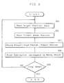
- Fig. 3 is a flow chart showing detailed processing procedures of rough and finishing grinding cycles shown in Fig. 2.
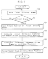
- Fig. 4 is a flow chart showing a detailed procedure of a wear rate detecting cycle shown in Fig. 2.
- Fig. 5 is an explanatory view showing the relationship between a rough grinding wheel G1 and a workpiece K at the end of the rough grinding operation.
- Fig. 6 is an explanatory view showing the relationship between a finish grinding wheel G2 and the workpiece K prior to entering the finish grinding operation.
- the numeral 10 indicates a bed of the numerically controlled grinding machine, on which a table 11 driven by a servo motor 23 via a feed-screw mechanism, not shown, is disposed slidably in the direction of X-axis which is normal to a spindle axis.
- a headstock 12 supporting a spindle 13 rotated by a servo motor 14 is installed on the table 11.
- a workpiece K is attached to the spindle 13 by a chuck 18.
- a tool slide 20 is disposed slidably in the direction of Z-axis toward the workpiece K.
- motors 21 and 22 supporting and driving a rough grinding wheel G1 and a finish grinding wheel G2, respectively, are mounted through a wheel head 23 and on the wheel head 23,for example, an acoustic emission sensor, hereinafter referred to as AE sensor, 70 which detects sounds is disposed as a sensor for detecting the contact of finish grinding wheel G2 with the workpiece K.
- the AE sensor 70 is connected to a CPU 31 via an interface 34 of a numerical controller 30.
- the tool slide 20 is coupled to a servo motor 16 via a feed screw, not shown, so as to be moved back and forth by the servo motor 16 rotating forward or reverse.
- a dresser 60 having a dressing tool 61 and capable of changing the relative position between the tool 61 and the finish grinding wheel G2. Feed of the dressing tool 61 toward the finish grinding wheel G2, or feed in the direction of U-axis is controlled by a servo motor 63, and feed parallel to the grinding surface of the finish grinding wheel G2, or in the direction of W-axis is controlled by a servo motor 64.
- Drive units 50, 51, 52 are circuits for driving the servo motors 23, 14, 16, respectively, in response to the command pulses output from the numerical controller 30.
- drive units 53, 54 are circuits for driving the servo motors 63, 64, respectively.
- pulse encoders 24, 15, 17, 65, 66 for detecting their rotating positions are connected respectively, and outputs of each of the pulse encoders 24, 15, 17, 65, 55 are fed back to the drive units 50, 51, 52, 53, 54 to make a negative feed back loops.
- Present positions of the respective feed axes X, C, Z are memorized in RAM 35 and are renewed when a pulse distribution is executed by a drive CPUI36.
- present positions of each of the feed axes U, W are memorized in RAM38 and are renewed when a pulse distribution is executed by a drive CPUII 39.
- the numerical controller 30 is designed mainly to numerically control rotations of control axes to control grinding operation on the workpiece and dressing on the finish grinding wheel G2, and principally comprises the CPU31 for controlling the grinding machine, a ROM33 storing the controlling programs and a RAM32 storing input data and so on.
- an NC data memory 321 for storing the NC data a rough grinding wheel diameter memory 322 for storing the present diameter of the rough grinding wheel G1, a rough grinding wheel position memory 323 as a position memory means for storing the present position of the grinding surface of the rough grinding wheel G1, a finish grinding wheel diameter memory 324 for storing the present diameter of the finish grinding wheel G2, a finish grinding wheel position memory 325 for storing the present position of the grinding surface of the finish grinding wheel G2, and a data diameter memory 326 as a data diameter memory means for memorizing a designed value of the diameter at the end of the rough grinding of the workpiece are formed.
- Contents of the rough grinding wheel position memory 323 and the finish grinding wheel position memory 325 are renewed at real time, by inputting the present invention data from the RAM35 whenever positions of respective wheels change.
- the drive CPUI36, the RAM35 and a pulse distribution circuit 37 are provided as a driving system of the servo motors 23, 14, 16, and the RAM38, the drive CPUII 39 and a pulse distribution circuit 40 are provided as a driving system of the servo motors 63, 64.
- the RAM35 is a memory in which positioning data for the rough grinding wheel G1, finish grinding wheel G2, table 11 and spindle 13 are input from the CPU31.
- the RAM38 is a memory in which positioning data for the dressing tool 61 is input from the main CPU31.
- the drive CPUI36 outputs at a constant interval data indicating moving amount within the interval and feed velocity based on the positioning data input in the RAM35
- the pulse distribution circuit 37 is a circuit for outputting command pulses to each of the drive units 50, 51, 52 based on the data output from the drive CPUI36.
- the drive CPUII 39 performs similarly as aforementioned based on the positioning data input in the RAM38 and the pulse distributing circuit 40 is a circuit for outputting command pulses to each of the drive units 53, 54 based on the data output from the drive CPUII 39.
- a tape reader 42 which inputs NC data
- a keyboard 43 which inputs data
- a CRT display 44 which displays data are connected via a input-output interface 41.
- the numerically controlled grinding machine of the present invention is controlled by the NC data stored in the NC data memory 321 in the RAM32 of the numerical controller 30. After the rough grinding of the workpiece is executed by the rough grinding wheel G1, the wear rate of the rough grinding wheel G1 is detected and the present position of the rough grinding wheel G1 is compensated in order to shift the position of the rough grinding wheel G1 in the succeeding rough grinding cycle. Then the finish grinding is performed by the finish grinding wheel G2.
- Step 200 in response to the read NC data, the rough grinding cycle is performed in accordance with the flow chart shown in Fig. 3.
- the target position is decoded from the NC data, and in the following Step 302, the present position of the rough grinding wheel G1 is read from the rough grinding wheel position memory 323.
- Step 304 then the difference between the present and target positions is calculated as a moving amount and output to the RAM35.
- the drive CPUI36 executes interpolations based on the moving amount and calculations of feed velocities for the slow-up and slow-down in order to output data indicating moving amount and velocity.
- the pulse distributing circuit 37 is driven, effecting the pulse distribution in proportion to the moving amount and driving the servo motors 23, 14, 16.
- the CPU31 determines whether it is the final step of the NC data in the rough grinding cycle. If NO, the procedure is returned to Step 300 and the next NC data are decoded. If YES, the grinding operation by the rough grinding cycle is completed. By the operation described above, the rough grinding cycle consisting of the rapid advance to a predetermined position, rough grinding feed, rapid retraction etc. of the rough grinding wheel G1 is executed by the NC data.
- the actual diameter of the workpiece K at the end of the rough grinding operation corresponds with the data diameter (theoretical diameter) ⁇ d1.
- the actual diameter of the rough grinding wheel G1 differs from the initial wheel diameter ⁇ D1 stored in the rough grinding wheel diameter memory 322 in advance, and changes from ⁇ D1, to ⁇ D2 ( ⁇ D2 ⁇ D1) by wear.
- the actual diameter of the workpiece K at the end the rough grinding operation is also, in practice, decreased from the data diameter ⁇ d1 to ⁇ d2 which is smaller by the unground amount T.
- Step 202 in Fig. 2 When the rough grinding operation is completed, the procedure is returned to Step 202 in Fig. 2 and a group of next NC data is decoded, and the table 11 is driven in the direction of X-axis such that the center line of the workpiece K corresponds with the axis of the finish grinding wheel G2, thereafter, the tool slide 20 is moved toward +Z and the finish grinding wheel G2 is inserted into the workpiece K.
- finish grinding wheel G2 a grinding wheel made of CBN is used, and is dressed by the dressing tool 61 of the dresser 60.
- the wheel diameter and the present position is monitored continuously and stored in the finish grinding wheel diameter memory 324 and the finish grinding wheel position memory 325 in the RAM32 of the numerical controller 30.
- the center line of the workpiece K corresponds with the axis of the finish grinding wheel G2.
- the present position of the grinding surface of the finish grinding wheel G2 at this time is stored as the initial value X0 of the finish grinding wheel G2.
- Step 204 the procedure is moved to Step 204, wherein the rough grinding wheel wear rate detecting cycle is executed as the procedures shown in Fig. 4.
- Step 100 by moving the table 11 in the direction of +X-axis by a unit amount, the finish grinding wheel G2 is relatively moved toward the inner wall of the workpiece K by the unit amount.
- the relative moving direction of the finish grinding wheel G2 when the table 11 is moved in the +X-axis direction is defined as the +X-axis direction.
- Step 102 it is determined whether or not the finish grinding wheel G2 contacts with the surface of the workpiece K based on a signal input from the AE sensor 70.
- Step 102 When it is determined NO in Step 102, that is no contact signal is generated, since the finish grinding wheel G2 does not contact with the surface of the workpiece K yet, the procedure is returned to Step 100.
- Step 100 While it is determined NO in Step 102, that is the contact signal is not detected, the process of Step 100 is repeatedly executed and the finish grinding wheel G2 is moved continuously in the +X-axis direction toward the inner wall of the workpiece K.
- the CPU31 moves its procedure to Step 104 composing position calculating means, and the contact position X1 is obtained by inputting to the CPU31 the contents of the finish grinding wheel position memory 325 when the contact signal from the AE sensor 70 is detected in Step 102.
- the CPU31 moves active execution to Step 106 composing present diameter calculating means, and the moving amount ⁇ x of the finish grinding wheel G2 is obtained by the following equation.
- ⁇ X
- the actual diameter ⁇ d2 of the workpiece K at the end of the rough grinding operation is calculated by the following equation.
- ⁇ d2 2 ⁇ X + ⁇ D f
- the unground amount T is, in other words, the wear rate of the rough grinding wheel G1.
- the diameter of the rough grinding wheel memorized in the rough grinding wheel diameter memory is compensated for to correspond with the actual diameter.
- the present position and diameter of the rough grinding wheel G1 are accurately compensated for. Then, in the succeeding rough grinding cycle, rapid advance, grinding feed etc. are controlled based on the latest values, that is the values ⁇ ND and NX stored in the rough grinding wheel diameter memory 322 and rough grinding wheel position memory 323.
- the CPU31 returns its procedure to Step 206 to execute the finish grinding cycle.
- the finish grinding cycle is executed with the aforesaid flow chart shown in fig. 3 which is used in the rough grinding cycle. In the finish grinding operation, however, for the present wheel position of Step 302, value stored in the finish grinding wheel position memory 325 is used. By the finish grinding cycle, the finish grinding operation is effected according to the NC data until the diameter of the workpiece K reaches to the finish diameter ⁇ d3.
- Step 208 wheel dressing processing of the finish grinding wheel is executed by the dresser 60.
- the wheel diameter stored in the finish grinding wheel diameter memory 324 is renewed into the theoretical diameter, and the present wheel position stored in the finish grinding wheel position memory 325 is compensated for the dressing amount. Feed amount in the rough grinding wheel wear rate detecting cycle and the finish grinding cycle thereafter are controlled based on these latest wheel diameter and present position.
- the rough grinding operation takes place based on the renewed present position of the rough grinding wheel G1 stored in the rough grinding wheel position memory 323 of the RAM32. That is, the present grinding surface position of the rough grinding wheel G1 is compensated for based on the wear of the rough grinding wheel G1 and the position thereof is accurately controlled.
- a vibrometer As a sensor for detecting the contact of finish grinding wheel G2 with the surface of the workpiece K, besides the AE sensor aforementioned, a vibrometer, a dynamometer etc. may also be used as far as capable of detecting sounds, vibration and the like.
- the size monitor can be achieved by reading out the value from the memory 322 and the operator is informed when to replace the wheel.
- allowances for machining by the finish grinding wheel at finish grinding operation can be controlled accurately, and the finish grinding operation is effected without applying excessive loads to the final grinding wheel.
- the accuracy of a final shape of a workpiece can be improved, and consequently wheel life of the finish grinding wheel can be lengthened.
- the present grinding machine includes a sensor for detecting the finish grinding wheel contacting with the workpiece surface when shifting from the rough grinding to finish grinding operations.
- the position of the finish grinding wheel is detected when a contact signal is output from the sensor.
- the numerical controller of the grinding machine calculates the difference between actual and theoretical sizes of the workpiece at completion of the rough grinding operation based on the finish grinding wheel position. After that, the controller compensates the rough grinding wheel position in the next machining cycle for the difference calculated by the controller.
- the finish grinding wheel those diameter is strictly controlled is used to calculate the actual workpiece size from its contact position with the workpiece, and with the difference between the actual size and theoretical size corresponding thereto, the rough grinding wheel position in the succeeding machining cycle is compensated for to control the rough grinding wheel position.
Landscapes
- Engineering & Computer Science (AREA)
- Human Computer Interaction (AREA)
- Manufacturing & Machinery (AREA)
- Physics & Mathematics (AREA)
- General Physics & Mathematics (AREA)
- Automation & Control Theory (AREA)
- Constituent Portions Of Griding Lathes, Driving, Sensing And Control (AREA)
Claims (4)
- Rectifieuse à commande numérique, dans laquelle une opération de rectification d'ébauche avec une meule d'ébauche et une opération de rectification de finition avec une meule de finition sont effectuées pour usiner une pièce d'oeuvre à une forme prédéterminée comprenant :
un moyen d'avancement pour déplacer ladite meule de finition en direction de ladite pièce d'oeuvre après la fin de ladite opération de rectification d'ébauche ;
un capteur pour émettre un signal lorsque la meule de finition contacte ladite surface de pièce d'oeuvre pendant le déplacement de ladite meule de finition par ledit moyen d'avancement ;
un moyen de détection de position pour détecter une position de ladite meule de finition lorsque ledit signal est émis par ledit capteur ;
un moyen de calcul pour obtenir la différence entre les dimensions réelle et théorique de ladite pièce d'oeuvre après la fin de ladite opération de rectification d'ébauche, en se basant sur ladite position de la meule de finition détectée par ledit moyen de détection de position ; et,
un moyen de compensation de position pour compenser, de la valeur de différence calculée par ledit moyen de calcul, ladite position de meule d'ébauche dans le cycle de rectification suivant. - Rectifieuse à commande numérique, selon la revendication 1, dans laquelle ledit moyen de calcul comprend :
un moyen de calcul du diamètre actuel pour calculer le diamètre actuel de la pièce d'oeuvre à partir de ladite position détectée par ledit moyen de détection de position ;
un moyen de mémorisation de diamètre donné pour mémoriser un diamètre donné de ladite pièce d'oeuvre après la fin de ladite opération de rectification d'ébauche ; et,
un moyen de calcul d'écart pour calculer la différence entre le diamètre actuel calculé par ledit moyen de calcul de diamètre actuel et le diamètre donné mémorisé dans ledit moyen de mémorisation de diamètre donné. - Rectifieuse à commande numérique, selon la revendication 2, dans laquelle ledit moyen de compensation de position comprend un moyen de compensation de donnée de position actuelle pour compenser la donnée de position actuelle de ladite meule d'ébauche en se basant sur l'écart calculé par ledit moyen de calcul d'écart.
- Rectifieuse à commande numérique, selon la revendication 3, comprenant en outre :
un moyen de mémorisation de donnée de position actuelle pour mémoriser la donnée de position actuelle de ladite meule d'ébauche, qui est compensée par ledit moyen de compensation de donnée de position actuelle.
Applications Claiming Priority (2)
| Application Number | Priority Date | Filing Date | Title |
|---|---|---|---|
| JP63189065A JP2637488B2 (ja) | 1988-07-28 | 1988-07-28 | 数値制御研削盤 |
| JP189065/88 | 1988-07-28 |
Publications (3)
| Publication Number | Publication Date |
|---|---|
| EP0352635A2 EP0352635A2 (fr) | 1990-01-31 |
| EP0352635A3 EP0352635A3 (en) | 1990-07-11 |
| EP0352635B1 true EP0352635B1 (fr) | 1994-01-12 |
Family
ID=16234710
Family Applications (1)
| Application Number | Title | Priority Date | Filing Date |
|---|---|---|---|
| EP89113352A Expired - Lifetime EP0352635B1 (fr) | 1988-07-28 | 1989-07-20 | Rectifieuse à commande numérique |
Country Status (4)
| Country | Link |
|---|---|
| US (1) | US4967515A (fr) |
| EP (1) | EP0352635B1 (fr) |
| JP (1) | JP2637488B2 (fr) |
| DE (1) | DE68912221T2 (fr) |
Cited By (2)
| Publication number | Priority date | Publication date | Assignee | Title |
|---|---|---|---|---|
| CN102501177A (zh) * | 2011-11-04 | 2012-06-20 | 厦门大学 | 一种精密数控磨床平衡装置及其平衡方法 |
| CN104647169A (zh) * | 2015-02-06 | 2015-05-27 | 黎建军 | 一种数控联动全自动斜槽加工磨床 |
Families Citing this family (32)
| Publication number | Priority date | Publication date | Assignee | Title |
|---|---|---|---|---|
| DE3918127C1 (fr) * | 1989-06-03 | 1990-12-13 | Man Roland Druckmaschinen Ag, 6050 Offenbach, De | |
| JPH0329257U (fr) * | 1989-07-31 | 1991-03-22 | ||
| JPH0790461B2 (ja) * | 1989-08-30 | 1995-10-04 | セイコー精機株式会社 | 研削盤用数値制御装置 |
| DE4025522A1 (de) * | 1990-08-11 | 1992-02-13 | Wolter Doll Dieter | Verfahren und vorrichtung zur erkennung von bearbeitungsfehlern, insbesondere von schleifmaschinen |
| US5138799A (en) * | 1991-04-12 | 1992-08-18 | Bryant Grinder Corporation | Probe positioning mechanism for a radius dresser |
| JPH05353U (ja) * | 1991-06-25 | 1993-01-08 | 株式会社イナツクス | 板状建材の研磨装置 |
| FR2680477B1 (fr) * | 1991-08-22 | 1995-12-08 | Pont A Mousson | Procede et machine d'ebarbage. |
| US5384950A (en) * | 1994-05-12 | 1995-01-31 | Harnischfeger Corporation | Method for machining a component |
| US6144892A (en) * | 1996-02-08 | 2000-11-07 | Royal Master Grinders, Inc. | Gauging system |
| US5674106A (en) * | 1996-02-08 | 1997-10-07 | Royal Masters Grinders, Inc. | Centerless grinder assembly and method of operating the same |
| US5919081A (en) * | 1996-09-04 | 1999-07-06 | Unova Ip Corporation | Method and apparatus for computer numerically controlled pin grinder gauge |
| US5816892A (en) * | 1997-02-06 | 1998-10-06 | Cobra Machine Tool Co., Inc. | Positioning control for combined milling machine and internally positioned grinding wheel |
| US6227938B1 (en) | 1998-09-08 | 2001-05-08 | Royal Masters Grinders, Inc. | Guidewire position locator |
| JP2001260021A (ja) * | 2000-03-16 | 2001-09-25 | Toshiba Mach Co Ltd | ロール研削盤の数値制御装置 |
| JP4048434B2 (ja) * | 2003-09-01 | 2008-02-20 | 株式会社ジェイテクト | 溝加工方法及び数値制御装置 |
| DE102005050209A1 (de) * | 2005-10-20 | 2007-04-26 | Ott, Reinhold, Waterloo | Vorrichtung zur Einspeisung eines Videosignals in eine Anzeigevorrichtung und Betriebsverfahren hierfür |
| DE102005050205A1 (de) * | 2005-10-20 | 2007-04-26 | Mtu Aero Engines Gmbh | Verfahren und Vorrichtung zum Kompensieren von Lage-und Formabweichungen |
| CN102218682B (zh) * | 2011-03-24 | 2013-03-13 | 新乡日升数控轴承装备股份有限公司 | 一种圆锥滚子数控磨床 |
| CN102744683B (zh) * | 2012-07-20 | 2014-04-16 | 浙江石轴数控设备有限公司 | 一种数控圆锥轴承内圈凸度成形磨床控制系统及其方法 |
| JP5926705B2 (ja) * | 2013-06-26 | 2016-05-25 | 日本特殊陶業株式会社 | スパークプラグの製造方法 |
| US10300574B2 (en) | 2014-10-24 | 2019-05-28 | Velasa Sports, Inc. | Skate blade sharpening system |
| US9573236B2 (en) | 2015-05-28 | 2017-02-21 | Velasa Sports, Inc. | Skate blade sharpening system with alignment adjustment using alignment wheel |
| US9566682B2 (en) | 2014-10-24 | 2017-02-14 | Velasa Sports, Inc. | Skate blade retention mechanism |
| US9475175B2 (en) | 2014-10-24 | 2016-10-25 | Velasa Sports, Inc. | Grinding wheel arbor |
| US9902035B2 (en) | 2014-10-24 | 2018-02-27 | Velasa Sports, Inc. | Compact grinding wheel |
| US9669508B2 (en) * | 2014-10-24 | 2017-06-06 | Velasa Sports, Inc. | Grinding wheel with identification tag |
| USD793830S1 (en) | 2015-07-08 | 2017-08-08 | Velasa Sports, Inc. | Skate blade sharpening system |
| CN106425863B (zh) * | 2016-11-25 | 2019-03-19 | 重庆兴旺工具制造有限公司 | 一种磨型砂轮修形控制电路及其控制方法 |
| US11969851B2 (en) | 2020-07-31 | 2024-04-30 | Velasa Sports, Inc. | Skate blade sharpening system |
| DE102021113619B4 (de) * | 2021-05-26 | 2025-05-08 | Deckel Maho Pfronten Gmbh | Vorrichtung und Verfahren zum spanenden Bearbeiten von Bauteilen mit unbestimmten Abmaßen, wie Gussbauteilen, an einer Werkzeugmaschine |
| US12485339B2 (en) | 2022-10-14 | 2025-12-02 | Velasa Sports, Inc. | Skate blade clamping systems |
| CN117984162A (zh) * | 2022-11-01 | 2024-05-07 | 隆基绿能科技股份有限公司 | 硅棒的加工方法及装置、电子设备 |
Family Cites Families (11)
| Publication number | Priority date | Publication date | Assignee | Title |
|---|---|---|---|---|
| JPS5060883A (fr) * | 1973-10-01 | 1975-05-26 | ||
| US3881887A (en) * | 1973-12-19 | 1975-05-06 | Mcmaster Harold | Apparatus and method for grinding an elongated workpiece |
| US4118900A (en) * | 1976-03-29 | 1978-10-10 | Seiko Seiki Kabushiki Kaisha | Method for controlling grinding process |
| JPS53138598A (en) * | 1977-05-10 | 1978-12-04 | Inoue Japax Res Inc | Grinding device |
| US4154024A (en) * | 1977-10-19 | 1979-05-15 | Schatz Federal Bearings Co., Inc. | Electric control device for an automatic grinding machine |
| US4371942A (en) * | 1981-03-18 | 1983-02-01 | Cincinnati, Milacron Inc. | Method and apparatus for controlling an automatic set-up cycle of operation |
| JPS57194876A (en) * | 1981-05-21 | 1982-11-30 | Seiko Seiki Co Ltd | Controlling method of grinding machine |
| JPS5834746A (ja) * | 1981-08-20 | 1983-03-01 | Toshiba Mach Co Ltd | ロ−ル研削盤の制御装置 |
| US4524547A (en) * | 1983-09-06 | 1985-06-25 | Litton Industrial Products, Inc. | Automatic double disc grinder control cycle |
| JPS61226261A (ja) * | 1985-03-29 | 1986-10-08 | Toyoda Mach Works Ltd | 数値制御研削盤 |
| JPS62228358A (ja) * | 1987-02-04 | 1987-10-07 | Shinko Kogyo Kk | 刃物研磨機 |
-
1988
- 1988-07-28 JP JP63189065A patent/JP2637488B2/ja not_active Expired - Lifetime
-
1989
- 1989-07-19 US US07/381,974 patent/US4967515A/en not_active Expired - Fee Related
- 1989-07-20 DE DE89113352T patent/DE68912221T2/de not_active Expired - Fee Related
- 1989-07-20 EP EP89113352A patent/EP0352635B1/fr not_active Expired - Lifetime
Cited By (3)
| Publication number | Priority date | Publication date | Assignee | Title |
|---|---|---|---|---|
| CN102501177A (zh) * | 2011-11-04 | 2012-06-20 | 厦门大学 | 一种精密数控磨床平衡装置及其平衡方法 |
| CN102501177B (zh) * | 2011-11-04 | 2014-03-26 | 厦门大学 | 一种精密数控磨床平衡装置及其平衡方法 |
| CN104647169A (zh) * | 2015-02-06 | 2015-05-27 | 黎建军 | 一种数控联动全自动斜槽加工磨床 |
Also Published As
| Publication number | Publication date |
|---|---|
| DE68912221D1 (de) | 1994-02-24 |
| EP0352635A2 (fr) | 1990-01-31 |
| EP0352635A3 (en) | 1990-07-11 |
| JP2637488B2 (ja) | 1997-08-06 |
| JPH0241872A (ja) | 1990-02-13 |
| US4967515A (en) | 1990-11-06 |
| DE68912221T2 (de) | 1994-05-11 |
Similar Documents
| Publication | Publication Date | Title |
|---|---|---|
| EP0352635B1 (fr) | Rectifieuse à commande numérique | |
| JP3467807B2 (ja) | 研削装置 | |
| US4570386A (en) | Regulating wheel dressing system in centerless grinder | |
| EP0268887B1 (fr) | Commande numérique d'avancement pour une machine-outil | |
| JPH027790B2 (fr) | ||
| JPH0675818B2 (ja) | アンギユラ研削盤 | |
| JP2811515B2 (ja) | 非円形ワークの研削方法及び装置 | |
| JPH0236047A (ja) | 非真円形工作物加工用数値制御装置 | |
| US4956946A (en) | Numerically controlled grinding machine | |
| JP2846881B2 (ja) | 数値制御研削盤 | |
| US5183026A (en) | Method and apparatus for dressing an angular grinding wheel | |
| JPH06114683A (ja) | 数値制御研削盤 | |
| JPH06246615A (ja) | 非円形ワーク加工用数値制御装置 | |
| JP3344064B2 (ja) | 研削装置 | |
| JP3143656B2 (ja) | 研削装置 | |
| JP2661942B2 (ja) | Ncデータ作成装置 | |
| JPH0529815Y2 (fr) | ||
| JP2685832B2 (ja) | 数値制御研削盤 | |
| JP3809670B2 (ja) | 研削盤及びその制御方法 | |
| JP3413938B2 (ja) | 研削装置 | |
| JPS6125501B2 (fr) | ||
| JP3163792B2 (ja) | 数値制御研削盤 | |
| JP3120578B2 (ja) | 研削装置 | |
| RU2082584C1 (ru) | Способ управления точностью многопроходной механической обработки и устройство для его осуществления | |
| JP2592083B2 (ja) | 数値制御研削盤 |
Legal Events
| Date | Code | Title | Description |
|---|---|---|---|
| PUAI | Public reference made under article 153(3) epc to a published international application that has entered the european phase |
Free format text: ORIGINAL CODE: 0009012 |
|
| AK | Designated contracting states |
Kind code of ref document: A2 Designated state(s): DE FR GB |
|
| PUAL | Search report despatched |
Free format text: ORIGINAL CODE: 0009013 |
|
| AK | Designated contracting states |
Kind code of ref document: A3 Designated state(s): DE FR GB |
|
| 17P | Request for examination filed |
Effective date: 19901219 |
|
| 17Q | First examination report despatched |
Effective date: 19930310 |
|
| GRAA | (expected) grant |
Free format text: ORIGINAL CODE: 0009210 |
|
| AK | Designated contracting states |
Kind code of ref document: B1 Designated state(s): DE FR GB |
|
| REF | Corresponds to: |
Ref document number: 68912221 Country of ref document: DE Date of ref document: 19940224 |
|
| ET | Fr: translation filed | ||
| PG25 | Lapsed in a contracting state [announced via postgrant information from national office to epo] |
Ref country code: GB Effective date: 19940720 |
|
| PLBE | No opposition filed within time limit |
Free format text: ORIGINAL CODE: 0009261 |
|
| STAA | Information on the status of an ep patent application or granted ep patent |
Free format text: STATUS: NO OPPOSITION FILED WITHIN TIME LIMIT |
|
| 26N | No opposition filed | ||
| GBPC | Gb: european patent ceased through non-payment of renewal fee |
Effective date: 19940720 |
|
| PG25 | Lapsed in a contracting state [announced via postgrant information from national office to epo] |
Ref country code: FR Effective date: 19950331 |
|
| PG25 | Lapsed in a contracting state [announced via postgrant information from national office to epo] |
Ref country code: DE Effective date: 19950401 |
|
| REG | Reference to a national code |
Ref country code: FR Ref legal event code: ST |