EP0352645B2 - Elektr(on)isches Schalt- bzw. Regelgerät in Schmalbauweise, insbesondere Schaltuhr - Google Patents
Elektr(on)isches Schalt- bzw. Regelgerät in Schmalbauweise, insbesondere Schaltuhr Download PDFInfo
- Publication number
- EP0352645B2 EP0352645B2 EP89113393A EP89113393A EP0352645B2 EP 0352645 B2 EP0352645 B2 EP 0352645B2 EP 89113393 A EP89113393 A EP 89113393A EP 89113393 A EP89113393 A EP 89113393A EP 0352645 B2 EP0352645 B2 EP 0352645B2
- Authority
- EP
- European Patent Office
- Prior art keywords
- shell
- program carrier
- counter
- switching
- double
- Prior art date
- Legal status (The legal status is an assumption and is not a legal conclusion. Google has not performed a legal analysis and makes no representation as to the accuracy of the status listed.)
- Expired - Lifetime
Links
- 230000001105 regulatory effect Effects 0.000 title claims 6
- 230000015572 biosynthetic process Effects 0.000 description 4
- 238000010276 construction Methods 0.000 description 4
- 238000006073 displacement reaction Methods 0.000 description 4
- 238000005755 formation reaction Methods 0.000 description 4
- 230000000712 assembly Effects 0.000 description 3
- 238000000429 assembly Methods 0.000 description 3
- 238000011161 development Methods 0.000 description 3
- 230000018109 developmental process Effects 0.000 description 3
- 238000009434 installation Methods 0.000 description 2
- 239000010453 quartz Substances 0.000 description 2
- VYPSYNLAJGMNEJ-UHFFFAOYSA-N silicon dioxide Inorganic materials O=[Si]=O VYPSYNLAJGMNEJ-UHFFFAOYSA-N 0.000 description 2
- 240000000731 Fagus sylvatica Species 0.000 description 1
- 235000010099 Fagus sylvatica Nutrition 0.000 description 1
- 230000008901 benefit Effects 0.000 description 1
- 230000005540 biological transmission Effects 0.000 description 1
- 239000003990 capacitor Substances 0.000 description 1
- 230000008878 coupling Effects 0.000 description 1
- 238000010168 coupling process Methods 0.000 description 1
- 238000005859 coupling reaction Methods 0.000 description 1
- 239000013078 crystal Substances 0.000 description 1
- 230000001419 dependent effect Effects 0.000 description 1
- 238000005516 engineering process Methods 0.000 description 1
- 239000012634 fragment Substances 0.000 description 1
- 230000003993 interaction Effects 0.000 description 1
- 238000004519 manufacturing process Methods 0.000 description 1
- 238000000034 method Methods 0.000 description 1
- 230000000737 periodic effect Effects 0.000 description 1
- 230000008569 process Effects 0.000 description 1
- 230000033764 rhythmic process Effects 0.000 description 1
- 230000001360 synchronised effect Effects 0.000 description 1
- 230000036962 time dependent Effects 0.000 description 1
- 230000007704 transition Effects 0.000 description 1
Images


Classifications
-
- G—PHYSICS
- G04—HOROLOGY
- G04C—ELECTROMECHANICAL CLOCKS OR WATCHES
- G04C23/00—Clocks with attached or built-in means operating any device at preselected times or after preselected time-intervals
- G04C23/02—Constructional details
Definitions
- the invention relates to an electrical switching or Control device in a narrow design, especially a timer, according to the preamble of claim 1.
- the invention relates to a housing
- the lower part and upper part being one another opposite in the form of flat shells, one of which in each case at least one of the two with molded Sidewalls arranged and fitted by pluggable Unification to form a complete housing
- the switching elements are in the customary combination with other assemblies used functionally and their number is equal to the number selectable time levels for the circulation of the program carrier according to periodic switching program.
- the design is also of the desired type Possible application and the installation requirements have been determined, e.g. with visible time display for the entire time program in frontal view or only a part of it side view of part of the time program. This Aspects are particularly from detail questions of the Construction of the housing and installation of each Depending on assemblies.
- Time switches are known from DE-OS 26 00 409, where the construction principle on the designs in Frame standardized housing is built. Because of the Complexity of the components of time switches etc. and Therefore their principles need further developments more or less targeted details are concentrated.
- An electrical switching device of the type mentioned in the preamble of claim 1 is known from FR-A-2 504 723.
- This document describes a timer in Narrow construction, but with the feeling of Switching elements by a sensing lever on the inside of the Program carrier takes place and the transmission largely is housed in the interior of the program carrier.
- DE-PS 28 13 069 relates to an electrical timer which the program carrier sensed from the outside on the circumference but with gearbox and motor on boards in the axis are arranged behind the program carrier, whereby the time switch has a relatively large width.
- the object of the invention is a To create electrical switching device of the type mentioned, in which all the necessary assemblies can be accommodated in a housing that is as narrow as possible and space is still created for any additional rechargeable battery, the storage of the program carrier being ensured.
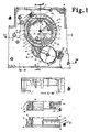
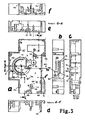
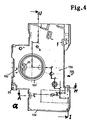
- Fig. 1 are broken-drawn sectors Cutouts for the heads 1 of the switching elements, the ring body 2 and the fitting 3 the stored on the tube combination 11
- Program carrier subgroup 20 can be seen more clearly, whose double pipe shell 4 visible, that in one piece or at least firmly on the base plate 5 of the lower part 6 of the housing attached, ie. is integrally formed.
- the program carrier sub-group 20 which is visible in fragments, is rotatably mounted on the double tube partial shell 4 as a tube bearing combination, one part of this rotary bearing containing a semicircular piece with the end pieces 7, 8 of the tube shell section and through the abutment pin pin 9 as a counter bearing is supplemented so that the ring-shaped program carrier group is fully supported.
- the double-pipe partial shell 4 has at one point in the exemplary embodiment in the middle between the ends of the tubular-shell section a tubular guide bushing 10 formed in the inner wall 52 of the double-pipe partial shell for centering the countershell by means of a counter-guide bushing 29 receiving the tubular guide bushing 10 (in Fig. 4), which is formed on the likewise not visible base plate of the upper part 195.
- the switching elements 12 and the guide grooves 13 of the molded body 14 for axial displacement of the switching elements 12 are visible in the left part, while in the right part between the segment-like cutouts, for example. 1, the switching elements 15 and the guide grooves 16 of the shaped bodies 17 for radial displacement of the switching elements 15 are visible.
- the empty surface 18 of the base plate 5 without any formations, which extends to the opposite end piece 7 with the interposition of the abutment pin pin 9.
- the program carrier group 19 has a ring gear 21 on the outer edge, over which it extends the drive group 22 is driven via the drive wheel 23.
- the scope of the program carrier is scanned by the projections of the switching elements 12 and 15 by means of the switching lever 25 which can be pivoted about the axis 24 and transmitted to the switch block, also not shown, via a contact intermediate lever 26, not shown here.
- Fig. 1c shows two designs of the program carrier, of which one (left) for axial displacement of the switching elements 12 in the molded body 62 and the adapter 63, and the ring gear 64 is guided and optionally the other design of the program carrier for radial displacement of the switching element 15 can be used in the molded body 66 with the adapter 67.
- One of these program carrier sub-groups 20 of your choice can be plugged onto the double-pipe partial shell 4, as a result of which the ring gear 64 is brought into engagement with the drive wheel 23.
- Fig. 1d is the program carrier sub-group 20 (same as the example of Fig. 1c left) with the outside visible time scale 68, the switching elements 12 and the ring gear 64 shown.
- the Program sub-group 20 is on the Double pipe shell 4 attached, the Time scale 68 over section 191 (in Fig. 1b) is visible.
- the bearing bush 28 (Fig. 1a) is the Flap cover, not shown, stored here.
- the drive group 22 receives a stacked gear in addition to the gear parts mentioned 141 composed of several gears with stator and coil 143 a group as form a compact, fully assembled unit.
- the switching lever is pivoted about the axis of the pivot bearing 108 by the protruding heads of the switching elements, the opposite end 107 actuates the movable contact 112 of the switch group 110 of the switch block 111 via the intermediate lever 133.
- the program carrier group 19 with bearing is therefore a module and coupled with the functionally following module switch block 111 via the shift lever 25 and the intermediate lever 133.
- the switch block 111 is together with the Contact set 112, 113 and the two terminals 114, 115 combined into an independent module.
- the switch block 111 With the manual shift lever 131, the either in two or depending on the concept or three positions can be set, can the switch block 111 additionally optionally from Time switch operation to "permanent ON” and if necessary, set “permanent OFF” from the outside, the shift lever 25 continuously from the switching elements is lifted off and the switch group 110 either in the "closed” position or "open” is blocked.
- the switch group 110 is, in principle, a so-called snap switch, whereby due to the interaction of the intermediate lever 133 and the spring 132, the movable jumpable contact 112 snaps during the transition from one operating position "open” to the other "closed", as can be seen in FIG. 5 recognizes where the contacts 112, 113 are closed because the contact 112 has snapped over the axis of the spring 132.
- the intermediate lever 133 has then been moved from the rest position to the bearing point 134 of the spring 132 by the opposite end 107 of the shift lever 25 as a result of the cam 106 of the shift lever 25 lifting off or by actuating the manual shift lever 131.
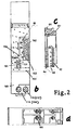
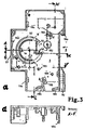
- FIG. 2b shows the time scale 68 with different positions of the switching elements 12 in its circumference 153 when the cover 151 is closed; Near the time scale 68, a recess is provided for actuating the operating mode switch - here as a manual shift lever 131 with two positions “timer operation” with the symbol “clock” and “permanent ON” (symbol “I”). At the lower end of the switch block 111, the terminals 114 , 115, 114 ', 115' are sunk finger-proof against electrical contact.
- a marking arrow 193 directed at the time scale 68 is arranged at the same height, so that the set switching time can be read comfortably and unmistakably on it.
- 2c shows the program carrier group 19 with time scale 68 and with switching elements to be actuated axially in the "ON"position; the upper part as a section (61, 64), the lower part as an external view (68, 64, 12).
- 2d is the bottom view of the time switch reproduced with the terminals 155.
- the lower part 6 is a in a conventional manner Snap device 92 for clamping the housing or the device on a mounting rail appropriate.
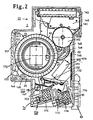
- a printed circuit board 171 (for example for the power supply unit) is mounted on the base plate 5 in the unoccupied surface parts of the interior of the housing.
- this contains a voltage divider to reduce the mains voltage to the operating voltage of drive group 22.
- an accumulator 172 is located on this circuit board 171 - taking advantage of the other parts or modules not required area - as an energy store for the power reserve in the absence or failure of the mains voltage, an electronic generator is installed as a "time base" 174, namely as an independent sub-assembly containing quartz crystal, rectifier, clock IC and capacitor.
- the circuit board 171 has connection points to the terminals 114, 115, 114 'and 115' at the end close to the drive group 22 and at the opposite end below the switch block 111 .
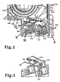
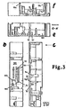
- Fig. 3a shows on the base plate 5 of the lower part 6 with partially raised side walls 181, the expediently one-piece overlays of the double pipe shell 4, various bolts 182, 183 and supports 184, guides 185, 186 for the clamps not used here, edge formations 187 for the Limiting the field of view to the timescale 68 and an integrally formed piece for the snap device 92.
- the double-tube partial shell 4 for the storage of the program carrier group 19 is again shown fully visible. It is double-walled from an outer, lower support 52 (see. Fig. 3c, e) and an inner, higher tube wall 53, the latter being a guide beech 10 for centering the to be placed on the double tube shell 4 (not shown here ) Has a counter shell.
- the two tube walls 52, 53 of the double tube partial shell 4 are broken off in the area outside the semicircle at this point at the end pieces 7 and 8 and a further segment also of different heights and approximately opposite the guide bush 10 is an abutment pin 9 to support the guide the double pipe shell 4 attached.
- combined snap and guide elements with a depression and snap spring 188 are integrally formed on the side walls 181 (see also FIGS. 3b to f).
- FIG. 3b shows the front view 189 from the outside with the wall of the operating unit and the window cutout 27 for the view of the program carrier which has not yet been installed here. Instead, you can see in this window section 27 the double-walled tubular shells of different heights 52, 53.
- the section 191 for the manual switch (operating mode switch) are the symbols for the operating mode switch from "timer operation"("I” ) on “continuous ON operation” or “continuous OFF operation” and the cutout 191 for the manual shift lever 131 .
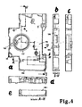
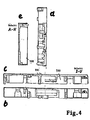
- FIGS. 4a to e are various views and sections of the upper part 195, including in view a) of the cover plate 196, on which, in addition to a few molded-on bolts, guide sets 185 and guide elements 188 for the clamps, especially the molded full ring of the counter shell 197
- Counter-guide bushing 29, which is molded in half-shell; together with the half-height wall parts 198 only include detailed formations for the double-pipe partial shell 4, because this upper part 195 is used after the complete fitting of the lower part 6 only as a kind of closure part with storage of the built-in individual parts. Only the cover 151 in front of the time scale 68 and the switching elements is stored in the bearing bush 28 .
- Fig. 4b shows in section the few pins and Sockets in front of the wall part 198; 4c shows one Exterior and front view, Fig.4d a front view and Fig.4e the bottom view.
Landscapes
- Physics & Mathematics (AREA)
- General Physics & Mathematics (AREA)
- Electric Clocks (AREA)
- Mechanical Control Devices (AREA)
- Switch Cases, Indication, And Locking (AREA)
- Switches With Compound Operations (AREA)
Priority Applications (1)
| Application Number | Priority Date | Filing Date | Title |
|---|---|---|---|
| AT89113393T ATE88286T1 (de) | 1988-07-26 | 1989-07-21 | Elektr(on)isches schalt- bzw. regelgeraet in schmalbauweise, insbesondere schaltuhr. |
Applications Claiming Priority (6)
| Application Number | Priority Date | Filing Date | Title |
|---|---|---|---|
| DE8809513U | 1988-07-26 | ||
| DE8809512U | 1988-07-26 | ||
| DE8809512U DE8809512U1 (de) | 1988-07-26 | 1988-07-26 | Elektr(on)isches Schalt- bzw. Regelgerät in Schmalbauweise, insbesondere Schaltuhr |
| DE19883825308 DE3825308A1 (de) | 1988-07-26 | 1988-07-26 | Elektr(on)isches schalt- bzw. regelgeraet in schmalbauweise, insbesondere schaltuhr |
| DE8809513U DE8809513U1 (de) | 1988-07-26 | 1988-07-26 | Elektr(on)isches Schalt- bzw. Regelgerät in Schmalbauweise, insbesondere Schaltuhr |
| DE3825308 | 1988-07-26 |
Publications (4)
| Publication Number | Publication Date |
|---|---|
| EP0352645A2 EP0352645A2 (de) | 1990-01-31 |
| EP0352645A3 EP0352645A3 (en) | 1990-08-22 |
| EP0352645B1 EP0352645B1 (de) | 1993-04-14 |
| EP0352645B2 true EP0352645B2 (de) | 1998-07-01 |
Family
ID=27197989
Family Applications (1)
| Application Number | Title | Priority Date | Filing Date |
|---|---|---|---|
| EP89113393A Expired - Lifetime EP0352645B2 (de) | 1988-07-26 | 1989-07-21 | Elektr(on)isches Schalt- bzw. Regelgerät in Schmalbauweise, insbesondere Schaltuhr |
Country Status (3)
| Country | Link |
|---|---|
| EP (1) | EP0352645B2 (es) |
| DE (1) | DE58904052D1 (es) |
| ES (1) | ES2039769T5 (es) |
Families Citing this family (2)
| Publication number | Priority date | Publication date | Assignee | Title |
|---|---|---|---|---|
| DE9003507U1 (de) * | 1990-03-26 | 1990-05-31 | Grässlin KG, 78112 St Georgen | Zeitschaltuhr |
| DE9319541U1 (de) * | 1993-12-20 | 1994-02-24 | Grässlin KG, 78112 St Georgen | Zeitschaltuhr |
Family Cites Families (5)
| Publication number | Priority date | Publication date | Assignee | Title |
|---|---|---|---|---|
| FR2291602A1 (fr) * | 1974-11-14 | 1976-06-11 | Legrand Sa | Dispositif d'action a intervention programmee, en particulier commutateur |
| DE2600409A1 (de) * | 1976-01-07 | 1977-07-21 | Westdeutsche Elektrogeraete | Elektrisches schaltgertaet, insbesondere zeitschaltgeraet |
| DE3025709A1 (de) * | 1980-07-07 | 1982-02-04 | Dieter Gräßlin Feinwerktechnik, 7742 St Georgen | Schaltuhr |
| FR2504723A1 (fr) * | 1981-04-24 | 1982-10-29 | Legrand Sa | Module interrupteur a programmation |
| DE8135821U1 (de) * | 1981-12-09 | 1986-01-02 | Dieter Gräßlin Feinwerktechnik, 7742 St. Georgen | Mehrbereichsschalteinrichtung |
-
1989
- 1989-07-21 ES ES89113393T patent/ES2039769T5/es not_active Expired - Lifetime
- 1989-07-21 DE DE8989113393T patent/DE58904052D1/de not_active Expired - Fee Related
- 1989-07-21 EP EP89113393A patent/EP0352645B2/de not_active Expired - Lifetime
Also Published As
| Publication number | Publication date |
|---|---|
| EP0352645A2 (de) | 1990-01-31 |
| ES2039769T3 (es) | 1993-10-01 |
| ES2039769T5 (es) | 1998-12-16 |
| EP0352645B1 (de) | 1993-04-14 |
| DE58904052D1 (de) | 1993-05-19 |
| EP0352645A3 (en) | 1990-08-22 |
Similar Documents
| Publication | Publication Date | Title |
|---|---|---|
| EP0708999B1 (de) | Antriebsvorrichtung für ein verstellbares fahrzeugteil | |
| DE10339316A1 (de) | Antriebsvorrichtung für Scheibenwischer mit einem Parkstellungsschalter | |
| DE69806452T2 (de) | Gerät zur Steuerung von elektrischen Fensterhebern | |
| DE2403289C3 (de) | Batteriebetriebene Weckeruhr | |
| WO2000024013A1 (de) | Stufenschalter | |
| EP0352645B2 (de) | Elektr(on)isches Schalt- bzw. Regelgerät in Schmalbauweise, insbesondere Schaltuhr | |
| DE2618537C3 (de) | Vorrichtung zum Verlängern des Betriebs von Scheibenwischanlagen in Kraftfahrzeugen | |
| DE3687452T2 (de) | Schalter fuer fernsteuerung eines motorgesteuerten kraftfahrzeugspiegels. | |
| DE1938482A1 (de) | Nockenschalter | |
| DE2150829C3 (de) | Digitaluhr mit einer Zeitanzeige durch elektrische Lampen | |
| EP0835196A1 (de) | Antriebsvorrichtung | |
| DE9308424U1 (de) | Stufenwähler mit Mehrfach-Grobwähler für Stufenschalter | |
| EP0176617A1 (de) | Elektronische Schaltuhr | |
| EP0962122A1 (de) | Regler, insbesondere temperaturregler wie raumtemperaturregler | |
| DE2249095C3 (de) | Einstellbare Drehwiderstandsanordnung | |
| DE3825308A1 (de) | Elektr(on)isches schalt- bzw. regelgeraet in schmalbauweise, insbesondere schaltuhr | |
| DE2432811A1 (de) | Synchronuhr mit elektrischer schalteinrichtung | |
| WO1989012904A1 (fr) | Generateur d'impulsions electriques travaillant mecaniquement | |
| DE884837C (de) | Elektrischer, von Hand einschaltbarer Zeitschalter | |
| EP0196581B1 (de) | Impulszähler als elektromechanisches Zählwerk mit Schwingspulenantrieb | |
| EP0660206B1 (de) | Zeitschaltuhr | |
| DE3013137C2 (es) | ||
| DE8809512U1 (de) | Elektr(on)isches Schalt- bzw. Regelgerät in Schmalbauweise, insbesondere Schaltuhr | |
| DE2814821C2 (de) | Vorrichtung zur Aufnahme der Betriebsschalter eines Kraftfahrzeuges | |
| DE8809513U1 (de) | Elektr(on)isches Schalt- bzw. Regelgerät in Schmalbauweise, insbesondere Schaltuhr |
Legal Events
| Date | Code | Title | Description |
|---|---|---|---|
| PUAI | Public reference made under article 153(3) epc to a published international application that has entered the european phase |
Free format text: ORIGINAL CODE: 0009012 |
|
| AK | Designated contracting states |
Kind code of ref document: A2 Designated state(s): AT BE CH DE ES FR GB IT LI |
|
| 17P | Request for examination filed |
Effective date: 19891229 |
|
| PUAL | Search report despatched |
Free format text: ORIGINAL CODE: 0009013 |
|
| RAP1 | Party data changed (applicant data changed or rights of an application transferred) |
Owner name: LEGRAND GMBH |
|
| AK | Designated contracting states |
Kind code of ref document: A3 Designated state(s): AT BE CH DE ES FR GB IT LI |
|
| 17Q | First examination report despatched |
Effective date: 19920122 |
|
| GRAA | (expected) grant |
Free format text: ORIGINAL CODE: 0009210 |
|
| AK | Designated contracting states |
Kind code of ref document: B1 Designated state(s): AT BE CH DE ES FR GB IT LI |
|
| PG25 | Lapsed in a contracting state [announced via postgrant information from national office to epo] |
Ref country code: IT Free format text: LAPSE BECAUSE OF FAILURE TO SUBMIT A TRANSLATION OF THE DESCRIPTION OR TO PAY THE FEE WITHIN THE PRESCRIBED TIME-LIMIT;WARNING: LAPSES OF ITALIAN PATENTS WITH EFFECTIVE DATE BEFORE 2007 MAY HAVE OCCURRED AT ANY TIME BEFORE 2007. THE CORRECT EFFECTIVE DATE MAY BE DIFFERENT FROM THE ONE RECORDED. Effective date: 19930414 Ref country code: BE Effective date: 19930414 |
|
| REF | Corresponds to: |
Ref document number: 88286 Country of ref document: AT Date of ref document: 19930415 Kind code of ref document: T |
|
| REF | Corresponds to: |
Ref document number: 58904052 Country of ref document: DE Date of ref document: 19930519 |
|
| PG25 | Lapsed in a contracting state [announced via postgrant information from national office to epo] |
Ref country code: AT Effective date: 19930721 |
|
| ET | Fr: translation filed | ||
| PG25 | Lapsed in a contracting state [announced via postgrant information from national office to epo] |
Ref country code: CH Effective date: 19930731 Ref country code: LI Effective date: 19930731 |
|
| GBT | Gb: translation of ep patent filed (gb section 77(6)(a)/1977) |
Effective date: 19930701 |
|
| REG | Reference to a national code |
Ref country code: ES Ref legal event code: FG2A Ref document number: 2039769 Country of ref document: ES Kind code of ref document: T3 |
|
| PLBI | Opposition filed |
Free format text: ORIGINAL CODE: 0009260 |
|
| 26 | Opposition filed |
Opponent name: ORBIS RELOJERIA INDUSTRIAL SA. Effective date: 19940113 |
|
| REG | Reference to a national code |
Ref country code: CH Ref legal event code: PL |
|
| APAA | Appeal reference recorded |
Free format text: ORIGINAL CODE: EPIDOS REFN |
|
| APAC | Appeal dossier modified |
Free format text: ORIGINAL CODE: EPIDOS NOAPO |
|
| APAC | Appeal dossier modified |
Free format text: ORIGINAL CODE: EPIDOS NOAPO |
|
| APAC | Appeal dossier modified |
Free format text: ORIGINAL CODE: EPIDOS NOAPO |
|
| PLAW | Interlocutory decision in opposition |
Free format text: ORIGINAL CODE: EPIDOS IDOP |
|
| PUAH | Patent maintained in amended form |
Free format text: ORIGINAL CODE: 0009272 |
|
| STAA | Information on the status of an ep patent application or granted ep patent |
Free format text: STATUS: PATENT MAINTAINED AS AMENDED |
|
| 27A | Patent maintained in amended form |
Effective date: 19980701 |
|
| AK | Designated contracting states |
Kind code of ref document: B2 Designated state(s): AT BE CH DE ES FR GB IT LI |
|
| REG | Reference to a national code |
Ref country code: CH Ref legal event code: AEN Free format text: AUFRECHTERHALTUNG DES PATENTES IN GEAENDERTER FORM |
|
| GBTA | Gb: translation of amended ep patent filed (gb section 77(6)(b)/1977) | ||
| ET3 | Fr: translation filed ** decision concerning opposition | ||
| REG | Reference to a national code |
Ref country code: ES Ref legal event code: DC2A Kind code of ref document: T5 Effective date: 19980916 |
|
| PGFP | Annual fee paid to national office [announced via postgrant information from national office to epo] |
Ref country code: ES Payment date: 20000704 Year of fee payment: 12 |
|
| PGFP | Annual fee paid to national office [announced via postgrant information from national office to epo] |
Ref country code: FR Payment date: 20010611 Year of fee payment: 13 |
|
| PGFP | Annual fee paid to national office [announced via postgrant information from national office to epo] |
Ref country code: GB Payment date: 20010615 Year of fee payment: 13 |
|
| PGFP | Annual fee paid to national office [announced via postgrant information from national office to epo] |
Ref country code: DE Payment date: 20010728 Year of fee payment: 13 |
|
| REG | Reference to a national code |
Ref country code: GB Ref legal event code: IF02 |
|
| PG25 | Lapsed in a contracting state [announced via postgrant information from national office to epo] |
Ref country code: GB Free format text: LAPSE BECAUSE OF NON-PAYMENT OF DUE FEES Effective date: 20020721 |
|
| PG25 | Lapsed in a contracting state [announced via postgrant information from national office to epo] |
Ref country code: ES Free format text: LAPSE BECAUSE OF NON-PAYMENT OF DUE FEES Effective date: 20020722 |
|
| PG25 | Lapsed in a contracting state [announced via postgrant information from national office to epo] |
Ref country code: DE Free format text: LAPSE BECAUSE OF NON-PAYMENT OF DUE FEES Effective date: 20030201 |
|
| GBPC | Gb: european patent ceased through non-payment of renewal fee |
Effective date: 20020721 |
|
| PG25 | Lapsed in a contracting state [announced via postgrant information from national office to epo] |
Ref country code: FR Free format text: LAPSE BECAUSE OF NON-PAYMENT OF DUE FEES Effective date: 20030331 |
|
| REG | Reference to a national code |
Ref country code: FR Ref legal event code: ST |
|
| REG | Reference to a national code |
Ref country code: ES Ref legal event code: FD2A Effective date: 20030811 |
|
| APAH | Appeal reference modified |
Free format text: ORIGINAL CODE: EPIDOSCREFNO |