EP0352684A1 - Modul für zylindrische starre Membranelemente zur Trennung, zum Filtrieren oder zur katalytischen Umwandlung - Google Patents
Modul für zylindrische starre Membranelemente zur Trennung, zum Filtrieren oder zur katalytischen Umwandlung Download PDFInfo
- Publication number
- EP0352684A1 EP0352684A1 EP89113553A EP89113553A EP0352684A1 EP 0352684 A1 EP0352684 A1 EP 0352684A1 EP 89113553 A EP89113553 A EP 89113553A EP 89113553 A EP89113553 A EP 89113553A EP 0352684 A1 EP0352684 A1 EP 0352684A1
- Authority
- EP
- European Patent Office
- Prior art keywords
- module according
- module
- elements
- parts
- envelope
- Prior art date
- Legal status (The legal status is an assumption and is not a legal conclusion. Google has not performed a legal analysis and makes no representation as to the accuracy of the status listed.)
- Granted
Links
- 239000012528 membrane Substances 0.000 title claims abstract description 10
- 238000001914 filtration Methods 0.000 title claims abstract description 9
- 238000000926 separation method Methods 0.000 title claims abstract description 5
- 230000009466 transformation Effects 0.000 title claims abstract description 5
- 125000006850 spacer group Chemical group 0.000 claims abstract description 13
- 230000003197 catalytic effect Effects 0.000 claims abstract description 4
- 239000000463 material Substances 0.000 claims description 10
- 239000002184 metal Substances 0.000 claims description 10
- 229910052751 metal Inorganic materials 0.000 claims description 10
- 239000007787 solid Substances 0.000 claims description 8
- 238000003466 welding Methods 0.000 claims description 6
- 229920001971 elastomer Polymers 0.000 claims description 5
- 239000000806 elastomer Substances 0.000 claims description 5
- 238000004026 adhesive bonding Methods 0.000 claims description 3
- 239000012530 fluid Substances 0.000 description 11
- 239000010935 stainless steel Substances 0.000 description 9
- 229910001220 stainless steel Inorganic materials 0.000 description 9
- 229910000831 Steel Inorganic materials 0.000 description 6
- 239000000919 ceramic Substances 0.000 description 6
- 238000000034 method Methods 0.000 description 6
- 239000010959 steel Substances 0.000 description 6
- PNEYBMLMFCGWSK-UHFFFAOYSA-N aluminium oxide Inorganic materials [O-2].[O-2].[O-2].[Al+3].[Al+3] PNEYBMLMFCGWSK-UHFFFAOYSA-N 0.000 description 4
- 230000006835 compression Effects 0.000 description 4
- 238000007906 compression Methods 0.000 description 4
- 229930182556 Polyacetal Natural products 0.000 description 3
- 229920006324 polyoxymethylene Polymers 0.000 description 3
- OKTJSMMVPCPJKN-UHFFFAOYSA-N Carbon Chemical compound [C] OKTJSMMVPCPJKN-UHFFFAOYSA-N 0.000 description 2
- 229920005176 Hostaform® Polymers 0.000 description 2
- PXHVJJICTQNCMI-UHFFFAOYSA-N Nickel Chemical compound [Ni] PXHVJJICTQNCMI-UHFFFAOYSA-N 0.000 description 2
- 229910052799 carbon Inorganic materials 0.000 description 2
- 239000002245 particle Substances 0.000 description 2
- 238000000108 ultra-filtration Methods 0.000 description 2
- UDHXJZHVNHGCEC-UHFFFAOYSA-N Chlorophacinone Chemical compound C1=CC(Cl)=CC=C1C(C=1C=CC=CC=1)C(=O)C1C(=O)C2=CC=CC=C2C1=O UDHXJZHVNHGCEC-UHFFFAOYSA-N 0.000 description 1
- 101150105088 Dele1 gene Proteins 0.000 description 1
- 229910001374 Invar Inorganic materials 0.000 description 1
- 229920005027 Ultraform® Polymers 0.000 description 1
- 230000000712 assembly Effects 0.000 description 1
- 238000000429 assembly Methods 0.000 description 1
- 238000005219 brazing Methods 0.000 description 1
- 238000011968 cross flow microfiltration Methods 0.000 description 1
- 230000010339 dilation Effects 0.000 description 1
- 238000009826 distribution Methods 0.000 description 1
- 239000000835 fiber Substances 0.000 description 1
- 239000011521 glass Substances 0.000 description 1
- 239000003292 glue Substances 0.000 description 1
- 238000001471 micro-filtration Methods 0.000 description 1
- 239000000203 mixture Substances 0.000 description 1
- 229910052759 nickel Inorganic materials 0.000 description 1
- 230000000149 penetrating effect Effects 0.000 description 1
- 238000004062 sedimentation Methods 0.000 description 1
- HBMJWWWQQXIZIP-UHFFFAOYSA-N silicon carbide Chemical compound [Si+]#[C-] HBMJWWWQQXIZIP-UHFFFAOYSA-N 0.000 description 1
- 229910010271 silicon carbide Inorganic materials 0.000 description 1
- 239000000126 substance Substances 0.000 description 1
- 238000005382 thermal cycling Methods 0.000 description 1
- 238000011144 upstream manufacturing Methods 0.000 description 1
Images


Classifications
-
- B—PERFORMING OPERATIONS; TRANSPORTING
- B01—PHYSICAL OR CHEMICAL PROCESSES OR APPARATUS IN GENERAL
- B01D—SEPARATION
- B01D46/00—Filters or filtering processes specially modified for separating dispersed particles from gases or vapours
- B01D46/54—Particle separators, e.g. dust precipitators, using ultra-fine filter sheets or diaphragms
- B01D46/543—Particle separators, e.g. dust precipitators, using ultra-fine filter sheets or diaphragms using membranes
-
- B—PERFORMING OPERATIONS; TRANSPORTING
- B01—PHYSICAL OR CHEMICAL PROCESSES OR APPARATUS IN GENERAL
- B01D—SEPARATION
- B01D53/00—Separation of gases or vapours; Recovering vapours of volatile solvents from gases; Chemical or biological purification of waste gases, e.g. engine exhaust gases, smoke, fumes, flue gases, aerosols
- B01D53/22—Separation of gases or vapours; Recovering vapours of volatile solvents from gases; Chemical or biological purification of waste gases, e.g. engine exhaust gases, smoke, fumes, flue gases, aerosols by diffusion
-
- B—PERFORMING OPERATIONS; TRANSPORTING
- B01—PHYSICAL OR CHEMICAL PROCESSES OR APPARATUS IN GENERAL
- B01D—SEPARATION
- B01D53/00—Separation of gases or vapours; Recovering vapours of volatile solvents from gases; Chemical or biological purification of waste gases, e.g. engine exhaust gases, smoke, fumes, flue gases, aerosols
- B01D53/34—Chemical or biological purification of waste gases
- B01D53/74—General processes for purification of waste gases; Apparatus or devices specially adapted therefor
- B01D53/86—Catalytic processes
-
- B—PERFORMING OPERATIONS; TRANSPORTING
- B01—PHYSICAL OR CHEMICAL PROCESSES OR APPARATUS IN GENERAL
- B01D—SEPARATION
- B01D63/00—Apparatus in general for separation processes using semi-permeable membranes
- B01D63/02—Hollow fibre modules
- B01D63/04—Hollow fibre modules comprising multiple hollow fibre assemblies
-
- B—PERFORMING OPERATIONS; TRANSPORTING
- B01—PHYSICAL OR CHEMICAL PROCESSES OR APPARATUS IN GENERAL
- B01D—SEPARATION
- B01D63/00—Apparatus in general for separation processes using semi-permeable membranes
- B01D63/06—Tubular membrane modules
- B01D63/066—Tubular membrane modules with a porous block having membrane coated passages
-
- B—PERFORMING OPERATIONS; TRANSPORTING
- B01—PHYSICAL OR CHEMICAL PROCESSES OR APPARATUS IN GENERAL
- B01D—SEPARATION
- B01D2313/00—Details relating to membrane modules or apparatus
- B01D2313/04—Specific sealing means
- B01D2313/042—Adhesives or glues
-
- B—PERFORMING OPERATIONS; TRANSPORTING
- B01—PHYSICAL OR CHEMICAL PROCESSES OR APPARATUS IN GENERAL
- B01D—SEPARATION
- B01D2313/00—Details relating to membrane modules or apparatus
- B01D2313/06—External membrane module supporting or fixing means
Definitions
- the present invention relates to a module for rigid cylindrical elements with a separation, filtration or catalytic transformation membrane.
- Such a module schematically comprises an envelope or casing in which said rigid elements which may be membranes or membrane supports are mounted.
- These elements which are made of a rigid material such as ceramic, glass, carbon or a metal, will be designated below by active elements.
- a module includes: - A generally cylindrical envelope made of a metal or a plastic material reinforced or not by fibers: - One or more active elements which generally have a tubular or quasi-tubular geometry, in particular of the multichannel type, as described in the following publications: ⁇ J. GILLOT and D. GARCERA - "New Ceramic Filter Media for Tangential Microfiltration and Ultrafiltration" - FILTRA 84 Conference - French filtration company Oct. 1984 PARIS. ⁇ J. GILLOT - G.
- BRINKMAN D. GARCERA - "New Ceramic Filter Media for Crossflow Microfiltration and Ultrafiltration”. Fourth World Filtration Congress 22-24 April 1986 - Ostende Belgium. and which are generally much longer in the direction of the channel than transversely to this channel.
- These active elements are assembled with the axis of their channel, or of their channels, parallel to the axis of the envelope.
- the membrane covers the inner surface of the channel or channels of these elements, or in some cases the outer surface, when it comes to tubes.
- a set of two end plates (usually very rigid) and seals which: . mechanically support the active elements at their two ends and hold them in position; . separate a region in the fluid treatment plant upstream and a downstream region relative to the membrane; . seal between these two regions.
- Such a module must be able to function for several years without being dismantled.
- differences in longitudinal expansion appear between the active elements, on the one hand, and the envelope and the candles, on the other hand, when the module is subjected to significant temperature variations, in particular when it is assembled. at room temperature and used at high or low temperatures. These differences in expansion can reach one to several millimeters when the active elements have a length of the order of one meter, which is common.
- this expansion gap is not controlled because the materials constituting the active elements on the one hand, the envelope and the candles on the other hand, are normally different since they meet different requirements.
- the use at high temperature tends to put the ceramic elements in tension, which they do not support well.
- the expansion gap is taken in two ways:
- the expansion gap must be absorbed by the joints located between the ends of the active elements and the plates d 'end.
- This requires at least one end of each element: - either a sliding joint whose tightness is then difficult to maintain in the event of thermal cycling, especially in the case where the fluid to be treated contains suspended particles (filtration) which are housed between the facing surfaces in the seal; - Either flexible seals which can be of the metal bellows type, which is very expensive, or of the elastomeric seal type.
- the joint must be wide enough laterally so that the angular deformation resulting from a longitudinal expansion gap of several millimeters remains acceptable, which results in an exaggerated size of the bundle of active elements. Furthermore, we then come up against the problems linked to the nature of the elastomers: lack of elasticity at cryogenic temperatures, and insufficient mechanical and chemical resistance at high temperatures for a long time in the presence of the fluids to be treated.
- the expansion gap can be absorbed by a sliding or flexible joint located at the periphery of an end plate, between this plate and the envelope.
- this solution has the drawback of transferring to the seals between the active elements and the end plates the forces coming from the difference in fluid pressure on either side of the end plates: these seals are then stressed in shear. In addition, these forces are then transmitted to the active elements themselves which are then stressed in tension or in compression. In the case of a tangential filtration with frequent unclogging of the membranes by pressure inversion, the filtering elements are then subjected to a succession of traction and compression, which is very unfavorable.
- the object of the invention is therefore to produce a module structure such that the end plates and the seals have to collect only small differences in residual expansion, due for example to a poor distribution of temperatures at inside the module.
- the subject of the present invention is a module for rigid cylindrical elements with a separation, filtration or catalytic transformation membrane, said elements being housed in a generally cylindrical envelope parallel to these elements, and closed by a first end plate and a second end plate where the ends of said elements are fixed by means of seals, characterized in that these end plates are connected by at least one spacer made up of at least three juxtaposed oblong parts, the first part being solid with said first end plate, the third part being integral with said second end plate, the second part being fixed to the free ends of said first and said third part, the materials of these three parts being chosen so that their overall expansion is equal to that of said active elements.
- said spacer constitutes said envelope.
- said module comprises one or more spacers forming one or more candles placed between said end plates.
- said module comprises a spacer forming said envelope and at least one spacer forming at least one candle.
- said spacer is formed from three coaxial cylindrical parts.
- Lateral wedging means are advantageously provided between said parts, and / or between or at least one of said parts and one of the end plates.
- Said cylindrical parts can be joined at their ends directly by welding, shrinking, gluing.
- said cylindrical parts are secured at their ends by means of welded, screwed, shrink-wrapped, glued rings, said rings possibly further constituting shims between said cylindrical parts.
- each piece of said candle is formed of n solid rods parallel to each other and to said active elements.
- said rods pass through lateral guide rings in which either they slide or they are fixed.
- one of the rods may have one end penetrating a blind hole in an end plate.
- the invention also relates to a module, comprising at least one candle according to the invention and an envelope formed of a cylindrical piece, one end of which is rigidly fixed to said first end plate and the other end of which is connected sealingly to said second end plate by means of a deformable seal, said deformable seal being chosen from seals of the sliding type, bellows made of metal or of elastomer.
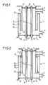
- a module 1 with two elements active 2 whose first ends are fixed in a first plate 4 with interposed seals 6, and whose second ends are fixed in a second plate 5 with interposed seals 7.
- a module generally comprises a bundle of active elements 2.
- Reference numbers 8 and 9 are given respectively, the inlet and the outlet of the fluid to be treated.
- the generally cylindrical lateral envelope which connects the two plates 4 and 5 is formed of three coaxial parts 10, 20, 30, the extreme edges of which are noted respectively (11, 12), (21, 22), ( 31, 32).
- the edges 11, 21 and 31 are located on the side of the first plate 4 while the edges 12, 22, 32 are located on the side of the second plate 5.
- the edge 12 is connected to the edge 22 and the edge 21 to the edge 31
- the parts 10, 20, 30 are chosen from materials such that the expansion of the envelope that they form is equal to that of the active elements 2 assembled in the module 1.
- a material with a coefficient of expansion higher than that of the parts 10 and 30 is chosen to make the part 20 so that, when the temperature increases, the elongation of the part 20 spreads the ends 12 and 31, which tends to bring the ends 11 and 32 of the module 1 closer together, thereby compensating for the excess elongation of the parts 10 and 30 relative to the active elements 2.
- lateral stops 13 and 23 are provided so as to ensure the wedging of each end of the part 20 relative to the end of the parts 10 and 30 to which it is not linked (wedging of the end 21 relative to the end 11, setting the end 22 relative to the end 32).
- the stops 13 and 23 are placed either on the intermediate piece 20 or on the pieces 10 and 30.
- the surface of the other piece which comes opposite the stop is machined so as to ensure free sliding.
- the tolerances are fixed to take account of the differences in expansion between parts 10, 20 and 30 perpendicular to their common axis.
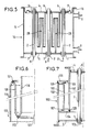
- FIG. 3 shows an example of a three-piece candle 40, 50, 60 according to the invention situated between the two end plates 4 and 5.
- parts 10, 20, 30, their ends are referenced (41, 51, 61), (42, 52, 62).
- parts 40, 50 and 60 are secured to each other by the same way as parts 10, 20, 30.
- FIG. 4 illustrates an alternative embodiment of a candle according to the invention in which the tubes are replaced by solid rods guided laterally or secured to two intermediate flanges 15 and 16.
- the central rod 70 secured at 71 to the flange 15 is intended to be fixed at its end 72 to the end plate 5 of the module.
- the three intermediate rods 80 have their ends 81, 82 linked respectively to the flanges 15 and 16.
- the three outer rods 90 have their ends 91 intended to be fixed to the end plate 4 of the module, while the ends 92 are fixed to the intermediate flange 16.
- the rods 80 and 90 are arranged in a star around the rod 70
- the rods 90 are offset by 360/3 degrees relative to each other and 360/3 x 2 degrees relative to the rods 80. (The number 3 is not limiting).
- the rod 70 can slide in the flange 6, while the rods 90 can slide in the flange 15.
- the rods can penetrate for lateral wedging into blind holes located in the end plate 4 or 5 on which they are not fixed.
- Concentric tube candles offer the advantage of less bulk than central tube and rod candles.
- the inner tube and the intermediate tube only follow the temperature variation with delay, which prevents good compensation for expansion.
- a particularly advantageous variant is therefore the use of candles in concentric tubes where the outer tube and the intermediate tube (and possibly the inner tube) have on their lateral surface openings intended to facilitate the circulation of the fluid in contact with the inner tube and the intermediate tube, so that their temperature always remains close to that of the fluid.
- the blind cavities located in the enclosure filled with the fluid to be treated preferably have their opening directed downwards, to prevent particles from accumulating there by sedimentation.
- FIG. 5 a module 14 intended to include a large number of active elements 2; we find the end plates 4 and 5.
- the envelope 15 is an ordinary cylindrical envelope.
- the end plate 5 is rigidly fixed to one of the ends of the casing 15 while the plate 4 is connected to the other end 16 by a deformable connection 17, which can be a flexible tight seal, such as than a metal or elastomer bellows, or a sliding joint.
- the two plates 4 and 5 are joined by candles 25 with temperature compensation similar to that of FIG. 3.
- a module of this type has the following characteristics: -
- the seals 6, 7 between the active elements 2 and the end plates 4, 5 do not have to compensate for dilation.
- the forces due to the difference in fluid pressure on either side of the end plates are collected by the candles and are therefore not transmitted either to the end joints 6, 7 of the active elements 2 or to these elements.
- an envelope 100 of axis 101 comprises three coaxial tubes 110, 120, 130 welded, glued, or shrunk directly on each other at 112 and 121.
- the ends of the tubes are flared or slightly closed for bring them together.
- axis envelopes 174 comprising three metal cylinders 171, 172, 173, secured by screwing by means of rings which also act as lateral shims. These rings are referenced 175 and 176 in Figure 8, 177 and 178 in Figure 9, 181 and 182 in Figure 10, 183 and 184 in Figure 11.
- rings are referenced 175 and 176 in Figure 8, 177 and 178 in Figure 9, 181 and 182 in Figure 10, 183 and 184 in Figure 11.
- An active element in alumina has a length of 1000 mm and a coefficient of expansion of 6.6 x 10 ⁇ 6 / ° C; we take an envelope of the prior art filled polyacetal; this is the product sold under the name HOSTAFORM C.9023 GFK, brand of the company HOECHST. Its coefficient of expansion is 50 x 10 ⁇ 6 / ° C.
- the envelope has a length of 1000 mm and a diameter of 80 mm. When the module goes from 20 ° C to 100 ° C, the expansion gap between the active element and the envelope is 3.5 mm.
- an envelope according to the invention comprising: - An inner cylinder, length 745 mm, diameter 390 mm and thickness 3 mm, made of Z30C13 stainless steel with an expansion coefficient of 11.5 x 10 ⁇ 6 / ° C. - An outer cylinder of the same length, the same thickness and of the same material as the inner cylinder and having a diameter of 410 mm. - An intermediate cylinder of length 670 mm, diameter 400 mm, and thickness 3 mm, made of stainless steel Z8CNDT 17-12 with an expansion coefficient of 17.5 x 10 ⁇ 6 / ° C.
- the module also includes a mixed candle with a tube and solid rods in accordance with FIG. 4. It is made up as follows: -
- the central tube 70 has a diameter of 40 mm, a thickness of 4 mm and a length of 745 mm.
- the three rods 90 have a diameter of 15 mm and a length of 745 mm; like the tube 70 they are in the same steel as the inner and outer cylinders forming the envelope.
- the rods 80 have a diameter of 15 mm and a length of 670 mm and are made of the same steel as the intermediate cylinder of the casing.
- the tube 70 has been welded while the rods 80 and 90 have been bolted to intermediate flanges.
- a module of the type described in FIG. 5 comprising: - a non-compensated expansion envelope, diameter 390 mm, thickness 5 mm and length 820 mm, made of Z30 C13 stainless steel having an expansion coefficient of 11.5 x 10 ⁇ 6 / ° C, - thirty active elements, - seven candles each of which includes . an inner tube 745 mm long, 20 mm in diameter and 3 mm thick in Z 30C13 steel, . an outer tube with a diameter of 34 mm, of the same length, same thickness and same composition, .
- These tubes are connected to each other by screwing on rings.
- the set of 30 active elements and of the seven candles is arranged in a hexagonal network configuration, so as to form a regular hexagon whose center and six vertices are occupied by the candles.
- a first end plate welded to one end of the envelope
- - a second end plate which is connected to the other end of the envelope by a flexible metal seal allowing a relative movement of 5 mm parallel to the axis of the module.
- the expansion gap between active elements and candles is less than 0.1 mm.
- the expansion gap between on the one hand the envelope, on the other hand the active elements and the candles is 1.1 mm. It is collected by the flexible metal seal.
- an envelope according to the invention comprising: - An inner cylinder of length 934 mm, diameter 80 mm and thickness 5 mm, in charged polyacetal having a coefficient of expansion of 50 x 10 ⁇ 6 / ° C: the product is the aforementioned HOSTAFORM C 9023 GFK.
- the expansion gap between the active elements and the envelope is less than 0.2 mm.
- an envelope according to the invention comprising: - An inner cylinder of length 970 mm, diameter 219 mm and thickness 2 mm, made of stainless steel Z6CND16 -4 with a coefficient of expansion of 10.8 x 10 ⁇ 6 / ° C. - An outer cylinder of the same length, the same thickness and of the same material as the inner cylinder and having a diameter 231 mm. - An intermediate cylinder of length 940 mm, diameter 225 mm, and thickness 2 mm, made of stainless steel Z35NCW15 having a coefficient of expansion of 17.5 x 10 ⁇ 6 / ° C.
- the expansion gap between the active elements and the envelope when going from 20 ° C to 300 ° C, is less than 0.1 mm.
- an envelope is produced according to the invention comprising: - An inner cylinder 800 mm long, 30 mm in diameter and 2 mm thick, made of 36% nickel stainless steel (INVAR) with a coefficient of expansion of 6.0 x 10 ⁇ 6 / ° C. - An outer cylinder, length 933 mm, diameter 40 mm and thickness 2 mm, made of Z12C13 stainless steel with a coefficient of expansion of 10.8 x 10 ⁇ 6 / ° C. - An intermediate cylinder of length 733 mm, diameter 35 mm and thickness 2 mm, made of stainless steel Z2CNDT 17-12 having a coefficient of expansion of 16.2 x 10 ⁇ 6 / ° C.
- the expansion gap between the active elements and the envelope is less than 0.1 mm.
Landscapes
- Chemical & Material Sciences (AREA)
- Chemical Kinetics & Catalysis (AREA)
- Engineering & Computer Science (AREA)
- Environmental & Geological Engineering (AREA)
- Analytical Chemistry (AREA)
- General Chemical & Material Sciences (AREA)
- Oil, Petroleum & Natural Gas (AREA)
- Health & Medical Sciences (AREA)
- Biomedical Technology (AREA)
- Separation Using Semi-Permeable Membranes (AREA)
- Connection Of Plates (AREA)
- Devices And Processes Conducted In The Presence Of Fluids And Solid Particles (AREA)
Applications Claiming Priority (2)
| Application Number | Priority Date | Filing Date | Title |
|---|---|---|---|
| FR8810280 | 1988-07-29 | ||
| FR8810280A FR2634668B1 (fr) | 1988-07-29 | 1988-07-29 | Module pour elements cylindriques rigides a membrane de separation, de filtration ou de transformation catalytique |
Publications (2)
| Publication Number | Publication Date |
|---|---|
| EP0352684A1 true EP0352684A1 (de) | 1990-01-31 |
| EP0352684B1 EP0352684B1 (de) | 1993-03-03 |
Family
ID=9368938
Family Applications (1)
| Application Number | Title | Priority Date | Filing Date |
|---|---|---|---|
| EP89113553A Expired - Lifetime EP0352684B1 (de) | 1988-07-29 | 1989-07-24 | Modul für zylindrische starre Membranelemente zur Trennung, zum Filtrieren oder zur katalytischen Umwandlung |
Country Status (8)
| Country | Link |
|---|---|
| US (1) | US4956087A (de) |
| EP (1) | EP0352684B1 (de) |
| JP (1) | JP2688256B2 (de) |
| KR (1) | KR0127638B1 (de) |
| CA (1) | CA1305430C (de) |
| DE (1) | DE68905105T2 (de) |
| ES (1) | ES2039770T3 (de) |
| FR (1) | FR2634668B1 (de) |
Cited By (1)
| Publication number | Priority date | Publication date | Assignee | Title |
|---|---|---|---|---|
| EP0821996A1 (de) * | 1996-08-01 | 1998-02-04 | Société des Ceramiques Techniques | Flüssigkeitsbehandlungsmodul mit steifer Membran und Gebrauchsverfahren desselben |
Families Citing this family (2)
| Publication number | Priority date | Publication date | Assignee | Title |
|---|---|---|---|---|
| RU2708861C2 (ru) | 2015-03-24 | 2019-12-11 | Арстрома Ко., Лтд. | Устройство разделения текучих сред, включающее мембрану для разделения текучих сред, и мембранный модуль для разделения текучих сред |
| CN106310927A (zh) * | 2015-06-16 | 2017-01-11 | 朱黎 | 一种恶臭气体净化处理系统 |
Citations (3)
| Publication number | Priority date | Publication date | Assignee | Title |
|---|---|---|---|---|
| EP0046889A1 (de) * | 1980-08-28 | 1982-03-10 | Akzo GmbH | Vorrichtung zur Wärme- und Stoffübertragung mittels Hohlfasern |
| EP0166994A1 (de) * | 1984-06-05 | 1986-01-08 | Nippon Steel Corporation | Gasscheidungsvorrichtung |
| US4632681A (en) * | 1985-04-25 | 1986-12-30 | Wheelabrator Corporation Of Canada, Ltd. | Locking apparatus for filter elements |
Family Cites Families (1)
| Publication number | Priority date | Publication date | Assignee | Title |
|---|---|---|---|---|
| FR2566282B1 (fr) * | 1984-06-20 | 1989-07-28 | Ceraver | Dispositif d'assemblage d'element filtrant tubulaire dans une enveloppe |
-
1988
- 1988-07-29 FR FR8810280A patent/FR2634668B1/fr not_active Expired - Fee Related
-
1989
- 1989-07-07 US US07/376,454 patent/US4956087A/en not_active Expired - Fee Related
- 1989-07-24 CA CA000606462A patent/CA1305430C/fr not_active Expired - Fee Related
- 1989-07-24 EP EP89113553A patent/EP0352684B1/de not_active Expired - Lifetime
- 1989-07-24 ES ES198989113553T patent/ES2039770T3/es not_active Expired - Lifetime
- 1989-07-24 DE DE8989113553T patent/DE68905105T2/de not_active Expired - Fee Related
- 1989-07-28 JP JP1196427A patent/JP2688256B2/ja not_active Expired - Lifetime
- 1989-07-28 KR KR1019890010721A patent/KR0127638B1/ko not_active Expired - Fee Related
Patent Citations (3)
| Publication number | Priority date | Publication date | Assignee | Title |
|---|---|---|---|---|
| EP0046889A1 (de) * | 1980-08-28 | 1982-03-10 | Akzo GmbH | Vorrichtung zur Wärme- und Stoffübertragung mittels Hohlfasern |
| EP0166994A1 (de) * | 1984-06-05 | 1986-01-08 | Nippon Steel Corporation | Gasscheidungsvorrichtung |
| US4632681A (en) * | 1985-04-25 | 1986-12-30 | Wheelabrator Corporation Of Canada, Ltd. | Locking apparatus for filter elements |
Cited By (2)
| Publication number | Priority date | Publication date | Assignee | Title |
|---|---|---|---|---|
| EP0821996A1 (de) * | 1996-08-01 | 1998-02-04 | Société des Ceramiques Techniques | Flüssigkeitsbehandlungsmodul mit steifer Membran und Gebrauchsverfahren desselben |
| FR2751895A1 (fr) * | 1996-08-01 | 1998-02-06 | Ceramiques Tech Soc D | Module de traitement de fluide(s) a membrane(s) rigide(s) et procedes le mettant en oeuvre |
Also Published As
| Publication number | Publication date |
|---|---|
| EP0352684B1 (de) | 1993-03-03 |
| JPH02149320A (ja) | 1990-06-07 |
| FR2634668B1 (fr) | 1990-09-14 |
| KR900001396A (ko) | 1990-02-27 |
| DE68905105D1 (de) | 1993-04-08 |
| JP2688256B2 (ja) | 1997-12-08 |
| KR0127638B1 (ko) | 1997-12-30 |
| US4956087A (en) | 1990-09-11 |
| DE68905105T2 (de) | 1993-06-17 |
| FR2634668A1 (fr) | 1990-02-02 |
| ES2039770T3 (es) | 1993-10-01 |
| CA1305430C (fr) | 1992-07-21 |
Similar Documents
| Publication | Publication Date | Title |
|---|---|---|
| CA2108698C (fr) | Module de filtration, de separation, de purification de gaz ou de liquide, ou de transformation catalytique | |
| EP1736233B1 (de) | Anorganisches Mehrkanal-Filterelement zum Filtrieren von Fluiden | |
| FR2878338A1 (fr) | Monture de lentille a focale variable | |
| FR2817994A1 (fr) | Panneau acoustique sandwich | |
| FR2776033A1 (fr) | Conditionneur d'ecoulement pour canalisation de transport de gaz | |
| EP2291840A1 (de) | Akustikplatte für eine ausstossdüse | |
| EP3055047B1 (de) | Lufttrennvorrichtung, inertisierungsvorrichtung und flugzeug mit derartiger vorrichtung | |
| FR2751895A1 (fr) | Module de traitement de fluide(s) a membrane(s) rigide(s) et procedes le mettant en oeuvre | |
| EP2740662B1 (de) | Verbesserte Verglasung für Flugzeuge | |
| EP1163036B1 (de) | Elemente-anordnung zur filtration, trennung oder reaktion, modul mit solcher anordnung und verfahren zur herstellung einer solchen anordnung oder eines solchen moduls | |
| EP3236301B1 (de) | Dichter demontierbarer stecker für lichtwellenleiter | |
| EP0352684B1 (de) | Modul für zylindrische starre Membranelemente zur Trennung, zum Filtrieren oder zur katalytischen Umwandlung | |
| FR2864576A1 (fr) | Bloc pour la filtration de particules contenues dans les gaz d'echappement d'un moteur a combustion interne | |
| WO2021083914A1 (fr) | Porte-diaphragme pour amortisseur de type oleopneumatique | |
| FR2672735A1 (fr) | Procede de fabrication d'une enveloppe sous pression pour une batterie oxyde metallique-hydrogene. | |
| FR2802115A1 (fr) | Installation de permeation | |
| EP1345672A1 (de) | Dichtung für ein filterelement und modul welcher ein mit einer derartigen dichtung ausgerüstetes filterelement aufweist | |
| EP3515584B1 (de) | Zylindrische wand zum filtern von feststoffpartikeln in einem fluid | |
| FR2630657A1 (fr) | Appareillage de filtration tangentielle | |
| FR2665646A1 (fr) | Dispositif comprenant un faisceau de tubes montes dans une calandre et presentant avec celle-ci une dilatation differentielle. | |
| FR2692162A3 (fr) | Module filtrant. | |
| CA2123812C (fr) | Unite inorganique de filtration comportant au moins un reseau integre de circulation d'un milieu liquide a traiter et/ou filtrat recupere | |
| FR3011483A1 (fr) | Dispositif de separation d'air, dispositif d'inertage et aeronef correspondants | |
| FR2896170A1 (fr) | Element de filtration | |
| FR2731514A1 (fr) | Dispositif de mesure annulaire pour la caracterisation de liaisons par brides |
Legal Events
| Date | Code | Title | Description |
|---|---|---|---|
| PUAI | Public reference made under article 153(3) epc to a published international application that has entered the european phase |
Free format text: ORIGINAL CODE: 0009012 |
|
| AK | Designated contracting states |
Kind code of ref document: A1 Designated state(s): BE CH DE ES FR GB IT LI NL SE |
|
| 17P | Request for examination filed |
Effective date: 19900730 |
|
| 17Q | First examination report despatched |
Effective date: 19920422 |
|
| GRAA | (expected) grant |
Free format text: ORIGINAL CODE: 0009210 |
|
| AK | Designated contracting states |
Kind code of ref document: B1 Designated state(s): BE CH DE ES FR GB IT LI NL SE |
|
| GBT | Gb: translation of ep patent filed (gb section 77(6)(a)/1977) |
Effective date: 19930304 |
|
| REF | Corresponds to: |
Ref document number: 68905105 Country of ref document: DE Date of ref document: 19930408 |
|
| ITF | It: translation for a ep patent filed | ||
| REG | Reference to a national code |
Ref country code: ES Ref legal event code: FG2A Ref document number: 2039770 Country of ref document: ES Kind code of ref document: T3 |
|
| PLBE | No opposition filed within time limit |
Free format text: ORIGINAL CODE: 0009261 |
|
| STAA | Information on the status of an ep patent application or granted ep patent |
Free format text: STATUS: NO OPPOSITION FILED WITHIN TIME LIMIT |
|
| 26N | No opposition filed | ||
| EAL | Se: european patent in force in sweden |
Ref document number: 89113553.5 |
|
| PGFP | Annual fee paid to national office [announced via postgrant information from national office to epo] |
Ref country code: BE Payment date: 20010706 Year of fee payment: 13 |
|
| PGFP | Annual fee paid to national office [announced via postgrant information from national office to epo] |
Ref country code: CH Payment date: 20010710 Year of fee payment: 13 |
|
| PGFP | Annual fee paid to national office [announced via postgrant information from national office to epo] |
Ref country code: DE Payment date: 20010717 Year of fee payment: 13 |
|
| PGFP | Annual fee paid to national office [announced via postgrant information from national office to epo] |
Ref country code: SE Payment date: 20010726 Year of fee payment: 13 |
|
| PGFP | Annual fee paid to national office [announced via postgrant information from national office to epo] |
Ref country code: FR Payment date: 20010727 Year of fee payment: 13 |
|
| PGFP | Annual fee paid to national office [announced via postgrant information from national office to epo] |
Ref country code: GB Payment date: 20010730 Year of fee payment: 13 |
|
| PGFP | Annual fee paid to national office [announced via postgrant information from national office to epo] |
Ref country code: NL Payment date: 20010731 Year of fee payment: 13 |
|
| PGFP | Annual fee paid to national office [announced via postgrant information from national office to epo] |
Ref country code: ES Payment date: 20010820 Year of fee payment: 13 |
|
| REG | Reference to a national code |
Ref country code: GB Ref legal event code: IF02 |
|
| PG25 | Lapsed in a contracting state [announced via postgrant information from national office to epo] |
Ref country code: GB Free format text: LAPSE BECAUSE OF NON-PAYMENT OF DUE FEES Effective date: 20020724 |
|
| PG25 | Lapsed in a contracting state [announced via postgrant information from national office to epo] |
Ref country code: SE Free format text: LAPSE BECAUSE OF NON-PAYMENT OF DUE FEES Effective date: 20020725 Ref country code: ES Free format text: LAPSE BECAUSE OF NON-PAYMENT OF DUE FEES Effective date: 20020725 |
|
| PG25 | Lapsed in a contracting state [announced via postgrant information from national office to epo] |
Ref country code: LI Free format text: LAPSE BECAUSE OF NON-PAYMENT OF DUE FEES Effective date: 20020731 Ref country code: CH Free format text: LAPSE BECAUSE OF NON-PAYMENT OF DUE FEES Effective date: 20020731 Ref country code: BE Free format text: LAPSE BECAUSE OF NON-PAYMENT OF DUE FEES Effective date: 20020731 |
|
| BERE | Be: lapsed |
Owner name: SOC. DES *CERAMIQUES TECHNIQUES Effective date: 20020731 |
|
| PG25 | Lapsed in a contracting state [announced via postgrant information from national office to epo] |
Ref country code: NL Free format text: LAPSE BECAUSE OF NON-PAYMENT OF DUE FEES Effective date: 20030201 Ref country code: DE Free format text: LAPSE BECAUSE OF NON-PAYMENT OF DUE FEES Effective date: 20030201 |
|
| EUG | Se: european patent has lapsed | ||
| REG | Reference to a national code |
Ref country code: CH Ref legal event code: PL |
|
| GBPC | Gb: european patent ceased through non-payment of renewal fee |
Effective date: 20020724 |
|
| PG25 | Lapsed in a contracting state [announced via postgrant information from national office to epo] |
Ref country code: FR Free format text: LAPSE BECAUSE OF NON-PAYMENT OF DUE FEES Effective date: 20030331 |
|
| NLV4 | Nl: lapsed or anulled due to non-payment of the annual fee |
Effective date: 20030201 |
|
| REG | Reference to a national code |
Ref country code: FR Ref legal event code: ST |
|
| REG | Reference to a national code |
Ref country code: ES Ref legal event code: FD2A Effective date: 20030811 |
|
| PG25 | Lapsed in a contracting state [announced via postgrant information from national office to epo] |
Ref country code: IT Free format text: LAPSE BECAUSE OF NON-PAYMENT OF DUE FEES;WARNING: LAPSES OF ITALIAN PATENTS WITH EFFECTIVE DATE BEFORE 2007 MAY HAVE OCCURRED AT ANY TIME BEFORE 2007. THE CORRECT EFFECTIVE DATE MAY BE DIFFERENT FROM THE ONE RECORDED. Effective date: 20050724 |