EP0352726A2 - Tête d'enregistrement par jet de liquide et appareil l'utilisant - Google Patents
Tête d'enregistrement par jet de liquide et appareil l'utilisant Download PDFInfo
- Publication number
- EP0352726A2 EP0352726A2 EP89113681A EP89113681A EP0352726A2 EP 0352726 A2 EP0352726 A2 EP 0352726A2 EP 89113681 A EP89113681 A EP 89113681A EP 89113681 A EP89113681 A EP 89113681A EP 0352726 A2 EP0352726 A2 EP 0352726A2
- Authority
- EP
- European Patent Office
- Prior art keywords
- liquid
- heat
- substrate
- path
- recording head
- Prior art date
- Legal status (The legal status is an assumption and is not a legal conclusion. Google has not performed a legal analysis and makes no representation as to the accuracy of the status listed.)
- Granted
Links
Images


Classifications
-
- B—PERFORMING OPERATIONS; TRANSPORTING
- B41—PRINTING; LINING MACHINES; TYPEWRITERS; STAMPS
- B41J—TYPEWRITERS; SELECTIVE PRINTING MECHANISMS, i.e. MECHANISMS PRINTING OTHERWISE THAN FROM A FORME; CORRECTION OF TYPOGRAPHICAL ERRORS
- B41J29/00—Details of, or accessories for, typewriters or selective printing mechanisms not otherwise provided for
- B41J29/377—Cooling or ventilating arrangements
-
- B—PERFORMING OPERATIONS; TRANSPORTING
- B41—PRINTING; LINING MACHINES; TYPEWRITERS; STAMPS
- B41J—TYPEWRITERS; SELECTIVE PRINTING MECHANISMS, i.e. MECHANISMS PRINTING OTHERWISE THAN FROM A FORME; CORRECTION OF TYPOGRAPHICAL ERRORS
- B41J2/00—Typewriters or selective printing mechanisms characterised by the printing or marking process for which they are designed
- B41J2/005—Typewriters or selective printing mechanisms characterised by the printing or marking process for which they are designed characterised by bringing liquid or particles selectively into contact with a printing material
- B41J2/01—Ink jet
- B41J2/135—Nozzles
- B41J2/14—Structure thereof only for on-demand ink jet heads
- B41J2/14016—Structure of bubble jet print heads
- B41J2/1408—Structure dealing with thermal variations, e.g. cooling device, thermal coefficients of materials
-
- B—PERFORMING OPERATIONS; TRANSPORTING
- B41—PRINTING; LINING MACHINES; TYPEWRITERS; STAMPS
- B41J—TYPEWRITERS; SELECTIVE PRINTING MECHANISMS, i.e. MECHANISMS PRINTING OTHERWISE THAN FROM A FORME; CORRECTION OF TYPOGRAPHICAL ERRORS
- B41J2/00—Typewriters or selective printing mechanisms characterised by the printing or marking process for which they are designed
- B41J2/005—Typewriters or selective printing mechanisms characterised by the printing or marking process for which they are designed characterised by bringing liquid or particles selectively into contact with a printing material
- B41J2/01—Ink jet
- B41J2/135—Nozzles
- B41J2/14—Structure thereof only for on-demand ink jet heads
- B41J2/14016—Structure of bubble jet print heads
- B41J2/14145—Structure of the manifold
-
- B—PERFORMING OPERATIONS; TRANSPORTING
- B41—PRINTING; LINING MACHINES; TYPEWRITERS; STAMPS
- B41J—TYPEWRITERS; SELECTIVE PRINTING MECHANISMS, i.e. MECHANISMS PRINTING OTHERWISE THAN FROM A FORME; CORRECTION OF TYPOGRAPHICAL ERRORS
- B41J2/00—Typewriters or selective printing mechanisms characterised by the printing or marking process for which they are designed
- B41J2/005—Typewriters or selective printing mechanisms characterised by the printing or marking process for which they are designed characterised by bringing liquid or particles selectively into contact with a printing material
- B41J2/01—Ink jet
- B41J2/135—Nozzles
- B41J2/14—Structure thereof only for on-demand ink jet heads
- B41J2002/14379—Edge shooter
-
- B—PERFORMING OPERATIONS; TRANSPORTING
- B41—PRINTING; LINING MACHINES; TYPEWRITERS; STAMPS
- B41J—TYPEWRITERS; SELECTIVE PRINTING MECHANISMS, i.e. MECHANISMS PRINTING OTHERWISE THAN FROM A FORME; CORRECTION OF TYPOGRAPHICAL ERRORS
- B41J2202/00—Embodiments of or processes related to ink-jet or thermal heads
- B41J2202/01—Embodiments of or processes related to ink-jet heads
- B41J2202/08—Embodiments of or processes related to ink-jet heads dealing with thermal variations, e.g. cooling
Definitions
- the present invention relates to a liquid-jet recording head having an ejection-energy-generating element, and more particularly to a recording head which can solve the problem caused by the heat from the ejection-energy-generating element.
- the present invention also relates to a recording apparatus having the above-mentioned recording head, and more particularly to a recording apparatus which can be miniaturized and simplified.
- liquid is ejected in minute liquid droplets driven by pressure change in a liquid path caused by strain of a piezoelectric element, or further the ejected liquid droplets are deflected by additional provision of a pair of electrodes.
- liquid is ejected by driving force of bubbles generated by abrupt heat generation in a heating element in a liquid path.
- the change of temperature of the recording liquid caused by the drive of the ejection-energy generating elements or by the heat transferred from the drive-signal transmitting circuit can sometimes be a serious factor.
- the reason is that a recording liquid will change the properties thereof such as surface tension and viscosity depending on the temperature, and that such change of properties will affect the ejected quantity, the feeding rate, etc. of the recording liquid.
- the temperature rise of the recording liquid is remarkable when a heat-generating element is employed. This temperature rise depends on the temperature rise of the substrate of the recording head where the heat-generating element is provided.
- systems have been employed in which the temperature rise of the substrate (hereinafter referred to as "a heat-generating substrate") is prevented.
- One of the systems is based on spontaneous cooling (air-cooling) in which a heat-generating substrate is attached onto a heat-conductive substrate so that superfluous portion of the heat energy generated by the heat-generating substrate may be released through the heat-conductive substrate to the surrounding atmosphere.
- Sho-57-138472 (1982) discloses a perforation construction of a substrate for supply of liquid from the back face to its front face adjacent to a common liquid chamber for the purpose of stable liquid supply from the common chamber to a plurality of liquid paths.
- This publication recognizes nothing about problems caused by the heat. The reason is clear from the fact that the construction disclosed by the Patent Publication includes very small contact region area between the liquid supply paths and the substrate so that the thermal variation is not influential.
- a recording head of liquid-jet recording apparatus employing liquid ejection energy, in particular, employing heat energy involves a problem that, when high-density recording such as solid priniting is practiced particularly in high velocity by high-frequency drive, the temperature of the recording head rises to cause abnormal bubbling, resulting in difficulty in formation of normal liquid droplets, and deterioration of quality of records caused by variation of dot diameter at a temperature higher than a certain level T1.
- the recording is simply stopped when the temperature of the recording head rises to a certain temperature T2 which is lower than temperature T1 until the temperature of the head falls, or otherwise the liquid temperature is lowered by conducting preliminary ejection as disclosed in British Patent No. 2,165,855, and thereafter the recording is re-started.
- T2 which is lower than temperature T1 until the temperature of the head falls, or otherwise the liquid temperature is lowered by conducting preliminary ejection as disclosed in British Patent No. 2,165,855, and thereafter the recording is re-started.
- T2 which is lower than temperature T1 until the temperature of the head falls, or otherwise the liquid temperature is lowered by conducting preliminary ejection as disclosed in British Patent No. 2,165,855, and thereafter the recording is re-started.
- the above-mentioned phenomenum of temperature rise is especially remarkable in recording heads made of a low-thermal-conductivty material such as a plastic.
- a construction employing a high-thermal-conductivity material for cooling is not suitable for miniaturization of the head because of a required large volume of heat radiation substrate to secure sufficient heat capacity.
- air-cooling type of heads involve problems that the recording is liable to be affected by environment and that the temperature cannot easily be controlled stably and effectively.
- heat is accumulated increasingly with lapse of time, causing temperature rise of the liquid, change of ejected liquid droplet diameter and ejecting rate, etc. with time, and non-uniformity of recording concentration from the beginning to the end of the record, which may not satisfy enough the need for stable recording in high quality.
- An object of the invention is to provide a liquid-jet recording head and a recording apparatus using the head which have solved the aforementioned problems of disadvantageous enlargement of the apparatus and increase of heat accumulation resulting from low heat radiation coefficient.
- Another object of the present invention is to provide a liquid-jet recording head and a recording apparatus using the head which enable high speed recording of high quality image independently of the time length of practice of recording.
- a further object of the present invention is to provide a liquid-jet recording head and a practically miniaturized and inexpensive recording apparatus using the head which enable reduction of thermal change rate of the liquid jet recording head without special driving, intermittance of the recording and enlargement of the recording apparatus.
- a still further object of the present invention is to provide a liquid-jet recording head which comprises a liquid-path-forming member having a heat capacity sufficient for adjusting substantially the temperature of the substrate at the side opposite to a liquid path for the ejection liquid in relation to a substrate having an ejection-energy-generating element.
- a liquid-jet recording head comprising an ejection opening for ejecting liquid; a first liquid path communicating to the ejection opening; and a substrate having an energy- generating element provided in correspondence with the ejection opening; said substrate being combined with a heat-capacity member for forming a second liquid path for supplying the liquid to the first liquid path.
- a recording apparatus comprising a liquid-jet recording head comprising an ejection opening for ejecting liquid; a first liquid path communicating to the ejection opening; and a substrate having an energy-generating element provided in correspondence with the ejection opening; said substrate being combined with a heat-capacity member for forming a second liquid path for supplying the liquid to the first liquid path, said apparatus further comprising a carriage for carrying the recording head, a driving motor, for driving the carriage, and a control means for supplying a driving signal in high speed for generating ejection energy at the recording head.
- a liquid-jet recording head comprising a substrate; a plurality of electrothermal energy transducers provided on the substrate in predetermined arrangement; first liquid paths provided on the substrate in correspondence respectively with each of the electrothermal energy tramsducers; a heat-conductive liquid-path-forming member for forming second liquid path in combination with the substrate and being in contact with the substrate at the side opposite to the first liquid paths in relation to the substrate, liquid paths formed of the first liquid paths and the second liquid path being bended.
- the heat accumulated in the substrate having an ejection-energy-generating means is efficiently released through a heat-capacity member provided at least in contact with a surface of the substrate, and the rise of the substrate temperature is suppressed by flow of the liquid through the liquid path formed by the heat-capacity member and the substrate to promote heat exchange.
- heat distribution can advantageously made uniform by forming a liquid path so as to introduce the liquid first to the center region of the arrangement and then toward the both ends of the arrangement.
- FIG. 2 an example of a liquid-jet recording apparatus is described which is provided with the recording head of the present invention.
- Recording heads 30 which eject respectively recording liquid of different color are fixed to a carriage 31 by a pressing members 31.
- the recording heads 30 in Fig. 2 are the ones shown in Fig. 1 and store recording liquid therein.
- the carriage 37 provided with the recording heads 30 moves in a reciprocative manner along a guide member 32 by driving force from a driving motor 38. Liquid is ejected in z direction to a recording medium 35, while the carriage is moving to conduct recording.
- a platen 33 is rotated by a motor 34, to deliver the recording 1edium 35.
- a flexible wiring 36 supplies electric signals for ejecting the recording liquid in z direction through a connecting member provided on the carriage 37.
- a control means 1000 controls the above-mentioned constitution of the devices to conduct recording in predetermined timing.
- the control means supplies drive signals to the aforementioned electrothermal energy transducer in a high speed in correspondence with the recording signals.
- the action of the control means 100 is controlled by a main switch 39 which switches on and off the apparatus.
- the apparatus in this example achieves high speed recording without employing a momentary stop mode and a conventional recovery means and operating mode therefor for avoiding loss of time.
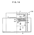
- Fig. 1A, Fig. 1B, and Fig. 1C show respectively a partial sectional view from the ejection opening side, a sectional side view perpendicular to the liquid paths directing to the ejection openings, and a plan view of the substrate, of a recording head of embodiment of the present invention.
- a heat-capacity member (or a cooling member) 1 of the present invention is provided in contact with the substrate 10.
- the heat-capacity member is formed from a resin with a metal dispersed therein which has larger heat capacity than the substrate and exhibits heat accumulation effect.
- the numeral 2 denotes a filter for removing dust from the recording liquid; 3 a cover plate; 4 an ejection opening or an orifice; 7 a common liquid chamber.
- the numeral 6 denotes a linear liquid path which introduces the recording liquid from the common liquid chamber to the ejection opening 4.
- a plurality of the liquid paths are arranged in a predetermined spacing, and are respectively provided with a heat-generating element 5 as an electrothermal energy transducer.
- the numerals 8 and 9 denote recording liquid tank separated by a filter 2; 10 a heat-generating substrate; 11 a wire bonding for connecting electrically the heat-generating substrate 10 with a lead frame 12.
- the heat-capacity member 1 is a hollowed member, and forms a liquid path 100 in combination with the substrate.
- the liquid path communicates a tank 8 to a common liquid chamber 7 through a liquid path 101 directing from the tank 8 to the substrate 10, and is perpendicular to the ejection direction of the liquid droplets and parallel to the heat-generating substrate 10.
- the recording liquid flows along the arrow marks from (A) to (D) in the Figs. More specifically, The recording liquid flows through the filter 2 with dust removed [(A)] and reaches the back face of the heat-capacity member 1 through a liquid path provided under the heat-capacity member [(B) and (C)], cooling the heat-capacity member by heat exchange.
- the recording liquid subsequently passes the liquid path 101 directing to the substrate 10 to cool the substrate 10 at the central region thereof, then flowing in the liquid path 100 in a direction perpendicular to the ejection of the flying liquid droplets and parallel to the heat-generating substrate to exchange heat with the substrate [(C), (D)].
- the recording liquid enters the common liquid chamber 7 located on the heat-generating substrate 10 from both end regions of arrangement of the ejection-energy-generating elements [D], then flowing into each of the liquid paths 6 [(E)] receiving heat energy form the heat generating element 5 to be ejected from ejection opening 4 by generation of bubbles [(F)], to conduct recording on the recording medium.
- the recording liquid is made to eject on receiving heat from the heat-generating substrate.
- the heat-capacity member 1 of the present invention is in contact with the heat-generating substrate 10, serving to receive the heat that is accumulated in the heat-generating substrate 10. Additionally, the liquid paths of the recording liquid provided in the heat-capacity member enable the effective heat exchange with the recording liquid.
- the movement of the recording liquid in the direction intersecting the arrangement of the energy-generating elements is advantageous in uniformization of temperature distribution throughout the substrate.
- the heat capacity of the heat-capacity member 1 is preferably larger for receiving a larger amount of heat accumulated in the heat-generating substrate.
- the heat capacity of not less than 0.1 J/K is preferable. With the heat capacity of less than 0.1 J/K, there may arise troubles such that the heat-capacity member cannot receive sufficient heat from the heat-generating substrate, or the temperature of the heat-capacity member rises abruptly to cause an abrupt temperature rise of the recording liquid.
- the upper limit for the heat capacity is not specified, the value of not more than 10 K/J is preferable for miniaturizing of recording heads.
- the contact area between the heat-capacity member 1 and the heat-generating substrate 10 is preferably not less than 40 % of the back face of the heat-generating substrate since a larger area is more effective in heat transfer.
- the upper limit is preferably 95 % for securing the liquid path from (C) to (D).
- the surface roughness of the heat-capacity member is preferably not higher than 25 ⁇ mRs(25S) in terms of center-line average roughness, and the surface undulation is preferably not higher than 40 ⁇ mW CA in terms of profile irregularity (three-wave center line undulation).
- the material for constituting the heat-capacity member may be a resin or a ceramic if it meets the requirement mentioned below, and is particularly preferably a metal having a high thermal conductivity such as copper, aluminum, bronze, beryllium, nickel, platinum, stainless steel, and steel.
- the thermal conductivity thereof is preferably not less than 5 J/m.S.K. If the thermal conductivity is less than 5 J/m.S.K, the heat received from the heat-generating substrate cannot be transferred to the recording liquid, not suppressing the temperature rise of the heat-generating substrate.
- a larger contact area between the recording liquid and the liquid path provided in the heat-capacity member is preferable for higher heat exchange rate, and the contact area of not less than 20 mm2 is preferable.
- the area of less than 20 mm2 may cause insufficient liquid paths, hindered flow of the recording liquid, and attachment of bubbles or dust.
- the heat-capacity member and the heat-generating substrate 10 (or the part thereof being integrated) is constructed as shown in Fig. 3 to take a stepped or finned structure so as to obtain a larger contact area with the recording liquid to exchange heat more effectively. Otherwise, a portion of the heat-capacity member 1 may be extended out of the liquid and provide a fin 1A to release the heat into the atmosphere.
- the liquid path formed in the heat-capacity member 1 be in any shape inasmuch as it enables effective heat exchange.
- the present invention can naturally applicable with effectiveness and ease to a full-line type of recording heads in which ejection openings are arranged over the full width of a recording medium.
- the rise of the temperature of the heat-capacity member itself can effectively be prevented by transferring the energy generated in a heat-generating element and accumulated in the heat-generating substrate into a heat-capacity member having a large heat capacity, and by subsequently releasing the heat to the recording liquid flowing in a liquid path formed in the heat-capacity member.
- the liquid can be ejected stably independently of recording speed and recording density, so that high-speed high-density recording can be made consistently and effectively.
- the present invention shows excellent effect particularly in recording heads and recording apparatus employing bubble jet systems among ink jet recording systems.
- the typical constructions and the principle thereof are disclosed, for example, by USP 4,723,129, and USP 4,740,796.
- the system of the present invention is applicable both to an on-demand type and to a continuous type.
- This system is particularly effective on-demand type since, in the system, heat energy is generated in an electrothermal transducer by applying a driving signal to the transducer located in corresponding with a sheet or a liquid path holding a liquid (or ink) to give rapid temperature rise exceeding nuclear boiling temperature corresponding to recording information and to give film boiling on the heating surface of the recording head, forming bubbles in one-to-one correspondence with driving signal.
- Liquid (or Ink) is ejected by the growth and constriction of the bubble through the ejection opening to form at least one droplet.
- Pulse type driving signal enables instantaneous and suitable growth and constriction of the bubble, achieving excellent responsiveness of ejection of liquid (or ink), and is preferable.
- Suitable driving signals of pulse type is described in USP 4,463,359 and USP 4,345,262. Additionally, more excellent recording is realized if the conditions described in USP 4,313,124 regarding the invention of temperature rise rate of the heat action surface mentioned above.
- the present invention covers the constitution of recording head such as combination of an ejection opening, a liquid path, and an electrothermal transducer (a linear liquid path or a rectangular liquid path) disclosed in the above cited patent specifications, and also a constitution having a heat action portion located in a bended region disclosed in USP 4,558,333 and USP 4,459,600. Further, the present invention is applicable effectively to constructions employing a common slit for ejection opening for electrothermal transducers disclosed by Japanese Patent Laid-open Application No. Sho-59-123670, and constructions having openings for absorbing pressure wave in correspondence with ejection openings disclosed in Japanese Patent Laid-open Application No. Sho-59-138461.
- a liquid-jet recording head comprises an ejection opening for ejecting liquid, a liquid path communicating to the ejection opening and a substrate having an energy-generating element provided in correspondence with the ejection opening.
- the substrate is combined with a heat-capacity member and the heat accumulated in the substrate is efficiently released through the heat-capacity member.
Landscapes
- Physics & Mathematics (AREA)
- Thermal Sciences (AREA)
- Particle Formation And Scattering Control In Inkjet Printers (AREA)
- Ink Jet (AREA)
- Accessory Devices And Overall Control Thereof (AREA)
Applications Claiming Priority (2)
| Application Number | Priority Date | Filing Date | Title |
|---|---|---|---|
| JP184691/88 | 1988-07-26 | ||
| JP18469188 | 1988-07-26 |
Publications (3)
| Publication Number | Publication Date |
|---|---|
| EP0352726A2 true EP0352726A2 (fr) | 1990-01-31 |
| EP0352726A3 EP0352726A3 (en) | 1990-11-28 |
| EP0352726B1 EP0352726B1 (fr) | 1994-04-27 |
Family
ID=16157684
Family Applications (1)
| Application Number | Title | Priority Date | Filing Date |
|---|---|---|---|
| EP89113681A Expired - Lifetime EP0352726B1 (fr) | 1988-07-26 | 1989-07-25 | Tête d'enregistrement par jet de liquide et appareil l'utilisant |
Country Status (4)
| Country | Link |
|---|---|
| US (1) | US5066964A (fr) |
| EP (1) | EP0352726B1 (fr) |
| JP (1) | JPH02125742A (fr) |
| DE (1) | DE68914897T2 (fr) |
Cited By (14)
| Publication number | Priority date | Publication date | Assignee | Title |
|---|---|---|---|---|
| EP0484034A1 (fr) * | 1990-10-31 | 1992-05-06 | Hewlett-Packard Company | Dispositif d'impression à jet d'encre thermique ayant refroidissement par changement de phase |
| EP0498293A3 (en) * | 1991-01-30 | 1992-10-28 | Canon Information Systems Research Australia Pty Ltd. | Bubblejet image reproducing apparatus |
| DE4127195A1 (de) * | 1991-08-15 | 1993-02-18 | Mannesmann Ag | Tintendruckkopf |
| EP0498292A3 (en) * | 1991-01-30 | 1993-02-24 | Canon Information Systems Research Australia Pty Ltd. | Integrally formed bubblejet print device |
| US5272491A (en) * | 1990-10-31 | 1993-12-21 | Hewlett-Packard Company | Thermal ink jet print device having phase change cooling |
| US5815173A (en) * | 1991-01-30 | 1998-09-29 | Canon Kabushiki Kaisha | Nozzle structures for bubblejet print devices |
| US5841452A (en) * | 1991-01-30 | 1998-11-24 | Canon Information Systems Research Australia Pty Ltd | Method of fabricating bubblejet print devices using semiconductor fabrication techniques |
| US6019457A (en) * | 1991-01-30 | 2000-02-01 | Canon Information Systems Research Australia Pty Ltd. | Ink jet print device and print head or print apparatus using the same |
| WO2000024584A1 (fr) * | 1998-10-24 | 2000-05-04 | Xaar Technology Limited | Appareil de depot de gouttelettes |
| US6499832B2 (en) | 2000-04-26 | 2002-12-31 | Samsung Electronics Co., Ltd. | Bubble-jet type ink-jet printhead capable of preventing a backflow of ink |
| US6533399B2 (en) | 2000-07-18 | 2003-03-18 | Samsung Electronics Co., Ltd. | Bubble-jet type ink-jet printhead and manufacturing method thereof |
| US6820966B1 (en) | 1998-10-24 | 2004-11-23 | Xaar Technology Limited | Droplet deposition apparatus |
| EP1518681A1 (fr) * | 2003-09-24 | 2005-03-30 | Hewlett-Packard Development Company, L.P. | Imprimante à jet d'encre |
| CN103302979A (zh) * | 2012-03-12 | 2013-09-18 | 兄弟工业株式会社 | 液滴喷射设备 |
Families Citing this family (22)
| Publication number | Priority date | Publication date | Assignee | Title |
|---|---|---|---|---|
| CA2062416C (fr) * | 1991-03-08 | 1997-12-30 | Seiichiro Karita | Tete d'enregistrement a jet d'encre et methode de protection de celle-ci |
| US5459498A (en) * | 1991-05-01 | 1995-10-17 | Hewlett-Packard Company | Ink-cooled thermal ink jet printhead |
| JPH06126964A (ja) * | 1992-10-16 | 1994-05-10 | Canon Inc | インクジェットヘッドおよび該インクジェットヘッドを備えたインクジェット記録装置 |
| US5472324A (en) * | 1994-06-10 | 1995-12-05 | Atwater; Richard G. | Page pack having novel heat sink arrangement for pump motor drive units |
| JPH1024582A (ja) * | 1996-07-12 | 1998-01-27 | Canon Inc | 液体吐出ヘッド並びに該液体吐出ヘッドの回復方法及び製造方法、並びに該液体吐出ヘッドを用いた液体吐出装置 |
| US5901425A (en) | 1996-08-27 | 1999-05-11 | Topaz Technologies Inc. | Inkjet print head apparatus |
| US5850234A (en) * | 1997-01-21 | 1998-12-15 | Xerox Corporation | Ink jet printhead with improved operation |
| EP0931650B1 (fr) * | 1997-06-17 | 2010-04-21 | Seiko Epson Corporation | Tete d'ecriture a jet d'encre |
| US6193349B1 (en) | 1997-06-18 | 2001-02-27 | Lexmark International, Inc. | Ink jet print cartridge having active cooling cell |
| US5818516A (en) * | 1997-07-21 | 1998-10-06 | Xerox Corporation | Ink jet cartridge having improved heat management |
| US6280013B1 (en) * | 1997-11-05 | 2001-08-28 | Hewlett-Packard Company | Heat exchanger for an inkjet printhead |
| US6007176A (en) * | 1998-05-05 | 1999-12-28 | Lexmark International, Inc. | Passive cooling arrangement for a thermal ink jet printer |
| WO1999062714A1 (fr) * | 1998-06-03 | 1999-12-09 | Lexmark International, Inc. | Structure de fixation de tete d'imprimante et procede correspondant |
| US6820959B1 (en) | 1998-06-03 | 2004-11-23 | Lexmark International, In.C | Ink jet cartridge structure |
| US6164762A (en) * | 1998-06-19 | 2000-12-26 | Lexmark International, Inc. | Heater chip module and process for making same |
| US6086195A (en) * | 1998-09-24 | 2000-07-11 | Hewlett-Packard Company | Filter for an inkjet printhead |
| US6065823A (en) * | 1999-04-16 | 2000-05-23 | Hewlett-Packard Company | Heat spreader for ink-jet printhead |
| GB0011916D0 (en) * | 2000-05-17 | 2000-07-05 | Cambridge Consultants | Printing |
| JP2004148788A (ja) * | 2002-11-01 | 2004-05-27 | Seiko Epson Corp | 液滴吐出装置及び方法、製膜装置及び方法、デバイス製造方法並びに電子機器 |
| US7625072B2 (en) * | 2004-07-22 | 2009-12-01 | Canon Kabushiki Kaisha | Ink jet recording head and recording apparatus |
| US20060284931A1 (en) * | 2005-06-16 | 2006-12-21 | Blair Dustin W | Print head having extended surface elements |
| US8517518B2 (en) | 2010-11-09 | 2013-08-27 | Canon Kabushiki Kaisha | Recording apparatus and liquid ejection head |
Family Cites Families (16)
| Publication number | Priority date | Publication date | Assignee | Title |
|---|---|---|---|---|
| CA1127227A (fr) * | 1977-10-03 | 1982-07-06 | Ichiro Endo | Procede d'enregistrement a jet liquide et appareil d'enregistrement |
| US4330787A (en) * | 1978-10-31 | 1982-05-18 | Canon Kabushiki Kaisha | Liquid jet recording device |
| US4345262A (en) * | 1979-02-19 | 1982-08-17 | Canon Kabushiki Kaisha | Ink jet recording method |
| US4463359A (en) * | 1979-04-02 | 1984-07-31 | Canon Kabushiki Kaisha | Droplet generating method and apparatus thereof |
| US4313124A (en) * | 1979-05-18 | 1982-01-26 | Canon Kabushiki Kaisha | Liquid jet recording process and liquid jet recording head |
| ATE3727T1 (de) * | 1979-07-04 | 1983-06-15 | Maschinenfabrik Rieter A.G. | Spinnereivorbereitungsmaschine. |
| JPS5644664A (en) * | 1979-09-21 | 1981-04-23 | Ricoh Co Ltd | Detecting and controlling device for temperature of ink in ink-jet recording device |
| US4558333A (en) * | 1981-07-09 | 1985-12-10 | Canon Kabushiki Kaisha | Liquid jet recording head |
| US4611219A (en) * | 1981-12-29 | 1986-09-09 | Canon Kabushiki Kaisha | Liquid-jetting head |
| JPS59123670A (ja) * | 1982-12-28 | 1984-07-17 | Canon Inc | インクジエツトヘツド |
| JPS59138472A (ja) * | 1983-01-28 | 1984-08-08 | Canon Inc | 液体噴射記録ヘッド |
| JPS59138461A (ja) * | 1983-01-28 | 1984-08-08 | Canon Inc | 液体噴射記録装置 |
| JPS60219060A (ja) * | 1984-04-17 | 1985-11-01 | Canon Inc | 液体噴射記録装置 |
| US4595526A (en) * | 1984-09-28 | 1986-06-17 | Colgate-Palmolive Company | High foaming nonionic surfacant based liquid detergent |
| US4723136A (en) * | 1984-11-05 | 1988-02-02 | Canon Kabushiki Kaisha | Print-on-demand type liquid jet printing head having main and subsidiary liquid paths |
| US4831390A (en) * | 1988-01-15 | 1989-05-16 | Xerox Corporation | Bubble jet printing device with improved printhead heat control |
-
1989
- 1989-07-25 DE DE68914897T patent/DE68914897T2/de not_active Expired - Fee Related
- 1989-07-25 EP EP89113681A patent/EP0352726B1/fr not_active Expired - Lifetime
- 1989-07-26 JP JP1191553A patent/JPH02125742A/ja active Pending
-
1991
- 1991-02-20 US US07/658,435 patent/US5066964A/en not_active Expired - Lifetime
Cited By (22)
| Publication number | Priority date | Publication date | Assignee | Title |
|---|---|---|---|---|
| US5272491A (en) * | 1990-10-31 | 1993-12-21 | Hewlett-Packard Company | Thermal ink jet print device having phase change cooling |
| EP0484034A1 (fr) * | 1990-10-31 | 1992-05-06 | Hewlett-Packard Company | Dispositif d'impression à jet d'encre thermique ayant refroidissement par changement de phase |
| US5841452A (en) * | 1991-01-30 | 1998-11-24 | Canon Information Systems Research Australia Pty Ltd | Method of fabricating bubblejet print devices using semiconductor fabrication techniques |
| EP0498292A3 (en) * | 1991-01-30 | 1993-02-24 | Canon Information Systems Research Australia Pty Ltd. | Integrally formed bubblejet print device |
| US5815173A (en) * | 1991-01-30 | 1998-09-29 | Canon Kabushiki Kaisha | Nozzle structures for bubblejet print devices |
| US6019457A (en) * | 1991-01-30 | 2000-02-01 | Canon Information Systems Research Australia Pty Ltd. | Ink jet print device and print head or print apparatus using the same |
| EP0498293A3 (en) * | 1991-01-30 | 1992-10-28 | Canon Information Systems Research Australia Pty Ltd. | Bubblejet image reproducing apparatus |
| DE4127195A1 (de) * | 1991-08-15 | 1993-02-18 | Mannesmann Ag | Tintendruckkopf |
| US6820966B1 (en) | 1998-10-24 | 2004-11-23 | Xaar Technology Limited | Droplet deposition apparatus |
| WO2000024584A1 (fr) * | 1998-10-24 | 2000-05-04 | Xaar Technology Limited | Appareil de depot de gouttelettes |
| AU762871B2 (en) * | 1998-10-24 | 2003-07-10 | Xaar Technology Limited | Droplet deposition apparatus |
| US6499832B2 (en) | 2000-04-26 | 2002-12-31 | Samsung Electronics Co., Ltd. | Bubble-jet type ink-jet printhead capable of preventing a backflow of ink |
| US6685846B2 (en) | 2000-04-26 | 2004-02-03 | Samsung Electronics Co., Ltd. | Bubble-jet type ink-jet printhead, manufacturing method thereof, and ink ejection method |
| US6533399B2 (en) | 2000-07-18 | 2003-03-18 | Samsung Electronics Co., Ltd. | Bubble-jet type ink-jet printhead and manufacturing method thereof |
| US6749762B2 (en) | 2000-07-18 | 2004-06-15 | Samsung Electronics Co., Ltd. | Bubble-jet type ink-jet printhead and manufacturing method thereof |
| EP1518681A1 (fr) * | 2003-09-24 | 2005-03-30 | Hewlett-Packard Development Company, L.P. | Imprimante à jet d'encre |
| US7429336B2 (en) | 2003-09-24 | 2008-09-30 | Phil Keenan | Inkjet printheads |
| US8206535B2 (en) | 2003-09-24 | 2012-06-26 | Hewlett-Packard Development Company, L.P. | Inkjet printheads |
| CN103302979A (zh) * | 2012-03-12 | 2013-09-18 | 兄弟工业株式会社 | 液滴喷射设备 |
| EP2639070A1 (fr) * | 2012-03-12 | 2013-09-18 | Brother Kogyo Kabushiki Kaisha | Appareil d'ejection de gouttelettes de liquide |
| US8888248B2 (en) | 2012-03-12 | 2014-11-18 | Brother Kogyo Kabushiki Kaisha | Liquid droplet jetting apparatus |
| CN103302979B (zh) * | 2012-03-12 | 2015-07-08 | 兄弟工业株式会社 | 液滴喷射设备 |
Also Published As
| Publication number | Publication date |
|---|---|
| DE68914897T2 (de) | 1994-08-25 |
| EP0352726B1 (fr) | 1994-04-27 |
| JPH02125742A (ja) | 1990-05-14 |
| US5066964A (en) | 1991-11-19 |
| DE68914897D1 (de) | 1994-06-01 |
| EP0352726A3 (en) | 1990-11-28 |
Similar Documents
| Publication | Publication Date | Title |
|---|---|---|
| EP0352726B1 (fr) | Tête d'enregistrement par jet de liquide et appareil l'utilisant | |
| EP0677387B1 (fr) | Couche de base pour tête à jet d'encre et tête à jet d'encre l'utilisant | |
| EP0245002B1 (fr) | Impression par projection d'encre | |
| US6766567B2 (en) | Ink jet print head having a porous ink supply layer | |
| US4831390A (en) | Bubble jet printing device with improved printhead heat control | |
| JP2010228465A (ja) | 小滴付着装置 | |
| HK1008845B (en) | Ink jet print head | |
| US5896147A (en) | Liquid jet head and substrate therefor having selected spacing between ejection energy generating elements | |
| EP1228875B1 (fr) | Procédé pour impression acoustique à encre utilisant une tête d'impression avec configuration bicouche | |
| US5467113A (en) | Ink-jet recording head, board for said head and ink-jet recording apparatus | |
| US5734398A (en) | Thermal ink jet printer and a method of driving the same | |
| US5214450A (en) | Thermal ink jet recording apparatus using a grouped transducer drive | |
| JP3190454B2 (ja) | インクジェット記録ヘッドおよびインクジェット記録装置 | |
| JP2002144540A (ja) | 記録ヘッド及びインクジェット記録装置 | |
| JP3267398B2 (ja) | インクジェットヘッドアセンブリ、および該インクジェットヘッドアセンブリの組み立て方法 | |
| US5633665A (en) | Ink jet recording method and apparatus | |
| JP2854405B2 (ja) | 液体飛翔記録ヘッドユニット | |
| JPH03187753A (ja) | 記録装置 | |
| JP3025584B2 (ja) | インクジェット記録装置およびインクカセット | |
| EP0478781B1 (fr) | Methode de placement d'un capteur de temperature sur un substrat d'une tete d'enregistrement par jet d'encre | |
| JPH0584922A (ja) | インクジエツト記録装置 | |
| JPH04305463A (ja) | インクジェット記録装置および該装置を用いる電子機器 | |
| JPH03281254A (ja) | インクジェット記録装置 | |
| JPH0343254A (ja) | 熱インクジェットの印字ヘッド | |
| JPH01285357A (ja) | 液体噴射記録装置 |
Legal Events
| Date | Code | Title | Description |
|---|---|---|---|
| PUAI | Public reference made under article 153(3) epc to a published international application that has entered the european phase |
Free format text: ORIGINAL CODE: 0009012 |
|
| AK | Designated contracting states |
Kind code of ref document: A2 Designated state(s): DE ES FR GB IT |
|
| PUAL | Search report despatched |
Free format text: ORIGINAL CODE: 0009013 |
|
| AK | Designated contracting states |
Kind code of ref document: A3 Designated state(s): DE ES FR GB IT |
|
| 17P | Request for examination filed |
Effective date: 19901221 |
|
| 17Q | First examination report despatched |
Effective date: 19920824 |
|
| GRAA | (expected) grant |
Free format text: ORIGINAL CODE: 0009210 |
|
| AK | Designated contracting states |
Kind code of ref document: B1 Designated state(s): DE ES FR GB IT |
|
| PG25 | Lapsed in a contracting state [announced via postgrant information from national office to epo] |
Ref country code: IT Free format text: LAPSE BECAUSE OF FAILURE TO SUBMIT A TRANSLATION OF THE DESCRIPTION OR TO PAY THE FEE WITHIN THE PRE;WARNING: LAPSES OF ITALIAN PATENTS WITH EFFECTIVE DATE BEFORE 2007 MAY HAVE OCCURRED AT ANY TIME BEFORE 2007. THE CORRECT EFFECTIVE DATE MAY BE DIFFERENT FROM THE ONE RECORDED.SCRIBED TIME-LIMIT Effective date: 19940427 Ref country code: ES Free format text: THE PATENT HAS BEEN ANNULLED BY A DECISION OF A NATIONAL AUTHORITY Effective date: 19940427 |
|
| REF | Corresponds to: |
Ref document number: 68914897 Country of ref document: DE Date of ref document: 19940601 |
|
| ET | Fr: translation filed | ||
| PLBE | No opposition filed within time limit |
Free format text: ORIGINAL CODE: 0009261 |
|
| STAA | Information on the status of an ep patent application or granted ep patent |
Free format text: STATUS: NO OPPOSITION FILED WITHIN TIME LIMIT |
|
| 26N | No opposition filed | ||
| REG | Reference to a national code |
Ref country code: GB Ref legal event code: IF02 |
|
| PGFP | Annual fee paid to national office [announced via postgrant information from national office to epo] |
Ref country code: DE Payment date: 20070719 Year of fee payment: 19 |
|
| PGFP | Annual fee paid to national office [announced via postgrant information from national office to epo] |
Ref country code: GB Payment date: 20070725 Year of fee payment: 19 |
|
| PGFP | Annual fee paid to national office [announced via postgrant information from national office to epo] |
Ref country code: FR Payment date: 20070710 Year of fee payment: 19 |
|
| GBPC | Gb: european patent ceased through non-payment of renewal fee |
Effective date: 20080725 |
|
| PG25 | Lapsed in a contracting state [announced via postgrant information from national office to epo] |
Ref country code: DE Free format text: LAPSE BECAUSE OF NON-PAYMENT OF DUE FEES Effective date: 20090203 |
|
| REG | Reference to a national code |
Ref country code: FR Ref legal event code: ST Effective date: 20090331 |
|
| PG25 | Lapsed in a contracting state [announced via postgrant information from national office to epo] |
Ref country code: GB Free format text: LAPSE BECAUSE OF NON-PAYMENT OF DUE FEES Effective date: 20080725 |
|
| PG25 | Lapsed in a contracting state [announced via postgrant information from national office to epo] |
Ref country code: FR Free format text: LAPSE BECAUSE OF NON-PAYMENT OF DUE FEES Effective date: 20080731 |