EP0352943B1 - Procédé de fabrication d'une plaque munie d'au moins un canal incorporé - Google Patents
Procédé de fabrication d'une plaque munie d'au moins un canal incorporé Download PDFInfo
- Publication number
- EP0352943B1 EP0352943B1 EP89307149A EP89307149A EP0352943B1 EP 0352943 B1 EP0352943 B1 EP 0352943B1 EP 89307149 A EP89307149 A EP 89307149A EP 89307149 A EP89307149 A EP 89307149A EP 0352943 B1 EP0352943 B1 EP 0352943B1
- Authority
- EP
- European Patent Office
- Prior art keywords
- fibers
- cross sectional
- channels
- fiber
- channel
- Prior art date
- Legal status (The legal status is an assumption and is not a legal conclusion. Google has not performed a legal analysis and makes no representation as to the accuracy of the status listed.)
- Expired - Lifetime
Links
Images

Classifications
-
- F—MECHANICAL ENGINEERING; LIGHTING; HEATING; WEAPONS; BLASTING
- F28—HEAT EXCHANGE IN GENERAL
- F28F—DETAILS OF HEAT-EXCHANGE AND HEAT-TRANSFER APPARATUS, OF GENERAL APPLICATION
- F28F21/00—Constructions of heat-exchange apparatus characterised by the selection of particular materials
- F28F21/08—Constructions of heat-exchange apparatus characterised by the selection of particular materials of metal
- F28F21/081—Heat exchange elements made from metals or metal alloys
- F28F21/087—Heat exchange elements made from metals or metal alloys from nickel or nickel alloys
-
- B—PERFORMING OPERATIONS; TRANSPORTING
- B29—WORKING OF PLASTICS; WORKING OF SUBSTANCES IN A PLASTIC STATE IN GENERAL
- B29C—SHAPING OR JOINING OF PLASTICS; SHAPING OF MATERIAL IN A PLASTIC STATE, NOT OTHERWISE PROVIDED FOR; AFTER-TREATMENT OF THE SHAPED PRODUCTS, e.g. REPAIRING
- B29C33/00—Moulds or cores; Details thereof or accessories therefor
- B29C33/0033—Moulds or cores; Details thereof or accessories therefor constructed for making articles provided with holes
-
- B—PERFORMING OPERATIONS; TRANSPORTING
- B29—WORKING OF PLASTICS; WORKING OF SUBSTANCES IN A PLASTIC STATE IN GENERAL
- B29C—SHAPING OR JOINING OF PLASTICS; SHAPING OF MATERIAL IN A PLASTIC STATE, NOT OTHERWISE PROVIDED FOR; AFTER-TREATMENT OF THE SHAPED PRODUCTS, e.g. REPAIRING
- B29C33/00—Moulds or cores; Details thereof or accessories therefor
- B29C33/44—Moulds or cores; Details thereof or accessories therefor with means for, or specially constructed to facilitate, the removal of articles, e.g. of undercut articles
- B29C33/48—Moulds or cores; Details thereof or accessories therefor with means for, or specially constructed to facilitate, the removal of articles, e.g. of undercut articles with means for collapsing or disassembling
- B29C33/50—Moulds or cores; Details thereof or accessories therefor with means for, or specially constructed to facilitate, the removal of articles, e.g. of undercut articles with means for collapsing or disassembling elastic or flexible
- B29C33/505—Moulds or cores; Details thereof or accessories therefor with means for, or specially constructed to facilitate, the removal of articles, e.g. of undercut articles with means for collapsing or disassembling elastic or flexible cores or mandrels, e.g. inflatable
-
- B—PERFORMING OPERATIONS; TRANSPORTING
- B29—WORKING OF PLASTICS; WORKING OF SUBSTANCES IN A PLASTIC STATE IN GENERAL
- B29C—SHAPING OR JOINING OF PLASTICS; SHAPING OF MATERIAL IN A PLASTIC STATE, NOT OTHERWISE PROVIDED FOR; AFTER-TREATMENT OF THE SHAPED PRODUCTS, e.g. REPAIRING
- B29C33/00—Moulds or cores; Details thereof or accessories therefor
- B29C33/76—Cores
-
- B—PERFORMING OPERATIONS; TRANSPORTING
- B29—WORKING OF PLASTICS; WORKING OF SUBSTANCES IN A PLASTIC STATE IN GENERAL
- B29C—SHAPING OR JOINING OF PLASTICS; SHAPING OF MATERIAL IN A PLASTIC STATE, NOT OTHERWISE PROVIDED FOR; AFTER-TREATMENT OF THE SHAPED PRODUCTS, e.g. REPAIRING
- B29C37/00—Component parts, details, accessories or auxiliary operations, not covered by group B29C33/00 or B29C35/00
- B29C37/0003—Discharging moulded articles from the mould
-
- F—MECHANICAL ENGINEERING; LIGHTING; HEATING; WEAPONS; BLASTING
- F28—HEAT EXCHANGE IN GENERAL
- F28F—DETAILS OF HEAT-EXCHANGE AND HEAT-TRANSFER APPARATUS, OF GENERAL APPLICATION
- F28F13/00—Arrangements for modifying heat-transfer, e.g. increasing, decreasing
-
- F—MECHANICAL ENGINEERING; LIGHTING; HEATING; WEAPONS; BLASTING
- F28—HEAT EXCHANGE IN GENERAL
- F28F—DETAILS OF HEAT-EXCHANGE AND HEAT-TRANSFER APPARATUS, OF GENERAL APPLICATION
- F28F21/00—Constructions of heat-exchange apparatus characterised by the selection of particular materials
- F28F21/08—Constructions of heat-exchange apparatus characterised by the selection of particular materials of metal
- F28F21/081—Heat exchange elements made from metals or metal alloys
- F28F21/085—Heat exchange elements made from metals or metal alloys from copper or copper alloys
-
- B—PERFORMING OPERATIONS; TRANSPORTING
- B29—WORKING OF PLASTICS; WORKING OF SUBSTANCES IN A PLASTIC STATE IN GENERAL
- B29C—SHAPING OR JOINING OF PLASTICS; SHAPING OF MATERIAL IN A PLASTIC STATE, NOT OTHERWISE PROVIDED FOR; AFTER-TREATMENT OF THE SHAPED PRODUCTS, e.g. REPAIRING
- B29C33/00—Moulds or cores; Details thereof or accessories therefor
- B29C33/02—Moulds or cores; Details thereof or accessories therefor with incorporated heating or cooling means
- B29C33/04—Moulds or cores; Details thereof or accessories therefor with incorporated heating or cooling means using liquids, gas or steam
Definitions
- the present invention relates to a method for producing a sheet member having at least one enclosed channel.
- Another prior art document DE-A-3,522,958 discloses a method of manufacturing an article having a base body which has a surface structure of channels, the method involving filling the channels with flexible, elastically extensible profile cords and depositing a cover layer over the base body and the profile cords. After the deposition has taken place, the profile cords are drawn out of the channels leaving behind a closed tubular structure.
- EP-A-0,170,178 relates to a removable core for the manufacture of tubular structures fibrous material.
- the core consists of a foam material externally covered with a heat shrink sleeving material. After a tubular structure has been formed on the surface of the core, the core is heated and the foam material softens or crumples. The core may then be removed from the tubular structure.
- a method for making a unitary article having a body with a plurality of enclosed fluid channels extending through said body comprising the steps of:
- the present invention provides a method for producing an article having at least one enclosed channel that is quickly and efficiently constructed and particularly adapted for producing multiple elongated channels of small diameter in a thin article.
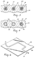
- the method of this invention includes the steps of providing at least one fiber 10 and arranging the fiber in a desired pattern, such as a row of parallel straight fibers as shown.
- the term "fiber” includes any slender elongate member having a desired cross sectional size and shape and formed from one or more filaments.
- a fiber may be formed by twisting or braiding multiple filaments so that the fiber has a helically fluted contour.
- Any of the one or more filaments forming the fiber may be solid or hollow.
- the fibers each are formed from a single cylindrical filament.
- the article of this invention is constructed by forming body 12 that envelopes the fibers, as shown in Figures 2 and 3, with at least one end of each fiber 10 extending beyond the body.
- Body 12 may be formed such as by molding or casting a plastic or ceramic material about the fibers so that the fiber's are completely enveloped by the material and channels 26 are produced in the body about each of the fibers.
- material such as copper and nickel is electrodeposited about the fibers to form body 12 that envelopes the fibers.
- One or more of the fibers includes an electrically conductive outer surface to attract the electrodepositable material.
- Non conductive fibers may interspersed with the conductive fibers.
- the electrically conductive outer surface of the fibers may be provided by constructing the fiber of electrically conductive material, such as a metallic material.
- the fiber may be constructed of a non conductive material, such as a polymeric material at core 16, with an electrically conductive layer 18, such as a metallic material, coated on the exterior of the core.
- fibers having non conductive surfaces are placed adjacent to a conductive plate (not shown) or the like so that the material electrodeposited on the conductive plate envelopes the fibers in a body as herein described.
- the conductive plate may remain with the body formed about the fibers, if desired.
- an article according to the present invention was produced by providing a continuous fiber of unoriented polypropylene having a circular cross section 0.007 inches (0.018 cm) in diameter.
- the fiber was wound about a pair of parallel threaded rods (not shown) 10 inches (25.4 cm) long and 0.75 inches (1.9 cm) in diameter spaced apart 3.00 inches (7.6 cm) center to center, forming a part of a rigid framework for supporting the fiber, so that the fiber formed two parallel rows of fiber segments extending between the parallel rods, each of the rows on opposite sides of the rods.
- the fiber segments in each row had a center to center spacing of 0.018 inches (0.046 cm) determined by the pitch of the threads on the rods.
- the fiber was adhered to the rods by applying an epoxy over the fiber and the threads on each of the rods. After the epoxy has solidified, one row of the fiber segments were cut away to provide unrestricted access to both sides of the fibers segments in the remaining row when immersed in the plating bath. The exposed portions of the fibers were then metallized to provide a conductive outer surface. All surfaces of the framework and fibers on which material was not to be electrodeposited were covered by a pressure sensitive adhesive vinyl tape.
- the framework and remaining row of fiber segments were first immersed in a nickel sulfamate bath (not shown) containing 110,5 g/l (16 ounces/gallon) of nickel; 3,45 g/l (0.5 ounces/gallon) of nickel bromide; and 27,6 g/l (4.0 ounces/gallon) of Boric acid.
- the remainder of the plating bath was filled with distilled water.
- a quantity of S-nickel Anode pellets were suspended by a Titanium basket in the plating bath.
- the plating bath was continuously filtered through a 5 micron filter.
- the temperature of the bath was maintained at 32,2°C (90°F).
- a Ph of 4.0 was maintained in the plating bath solution.
- a current density of 20 amps per square foot was applied to the fibers for three hours with the fibers and framework continuously rotated at six r.p.m. about an axis parallel to and equidistant between the threaded rods.
- An initial layer (22 in Figures 2,3,4, 5A,5B, and 5C) of nickel 0.003 inches (0.008 cm) thick was plated individually about each of the fibers, but a common body was not produced.
- the fibers and framework were then placed in a second plating bath containing 29 ounces/gallon of Copper Sulfate crystals; 8.0 ounces/gallon of Sulfuric Acid; 50 parts per million (ppm) of Hydrochloric Acid; Cuflex No. 321 (0.6%) and Cuflex No. 320H (0.3%) both marketed by McGean-Rocho Inc. of Cleveland, Ohio.
- the remainder of the second plating bath was filled with distilled water.
- a quantity of Phos-Copper Anode pellets were suspended by a Titanium basket in the plating bath.
- the plating bath was continuously filtered through a 5 micron filter. The temperature of the bath was maintained at 90°F.
- the framework and remaining row of fiber segments were immersed in the second plating bath and continuously rotated at six r.p.m. A current density of 60 amps per square foot was applied to the second plating bath and the fibers for eighteen hours. Upon removal, a body was produced having an average thickness of 0.075 inches (0.19 cm).
- the copper 24 electroformed about the outer layers of nickel in the Example forms a unitary body 12 about the fibers.
- the nickel defines channels 26 in the body that are resistant to many corrosive materials which may be circulated through the channels after the channels have been opened as described hereinafter, while the copper portion of the body provides efficient heat transfer characteristics.
- a body may be electroformed about the fiber using only one material, or more than two, if desired.
- the fiber After body 12 has been formed about the fibers, the fiber must be extracted from the body to open channels 26, as shown in Figures 2 and 4.
- the step of extracting the fibers from the body includes the process of changing the relative cross sectional areas of the channels within the body with respect to the cross sectional areas of the respective fibers within the channels so that the cross sectional areas of the channels are larger than the cross sectional areas of the fibers to facilitate the extraction of the fibers by pulling the fibers from the body. For instance, if the body is constructed of a material having a higher coefficient of thermal expansion than the coefficient of thermal expansion of the material used to construct the fibers, an increase in temperature of the body and fibers will result in the cross sectional areas of the channels increasing relative to the cross sectional areas of the fibers.
- the fibers are constructed from heat shrink tubing so that the application of heat will cause the heat shrink tubing to radially contract within a channel. Once the relative cross sectional areas of the channels has been increased with respect to the cross sectional areas of the fibers, the exposed ends of the fibers may be grasped externally of the body and a tensioning force applied to the fibers sufficient to extract the fibers from the body without exceeding the strength of the fibers.
- fibers may be provided that are inflatable. Once inflated, the body may be formed about the fibers as herein described. The fibers are then deflated and extracted from the channels.
- fiber 10 is constructed of material that is extensible in a longitudinal direction 27.
- Fibers constructed of polymeric materials may be used, such as elastomeric materials.
- fibers constructed of unoriented polypropylene have been found to be well adapted for use in the present method.
- the extensible fiber is removed from the body of the article by gripping the exposed end of the fiber and applying a tensioning force.
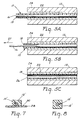
- the material of fiber 10 becomes oriented and elongated in a longitudinal direction, as shown in Figure 5B, and consequently the cross sectional area of the fiber will be reduced relative to the cross sectional area of the channel. Elongation of the entire fiber will enable fiber 10 to be removed from channel 26 with minimal resistance, as shown in Figure 5C. If desired, one or more of the fibers may be left in place in the body of the article.
- the fibers may be coated with a material that reduces the coefficient of friction between the fiber and the walls of the channel containing the fiber to reduce the force require to extract the fiber from the channel.
- Lubricants such as petroleum products or graphite powders may be used for this purpose.
- a fiber may be sheathed in an outer layer designed to separate from the fiber and remain in the channel after the remainder of the fiber is removed from the channel.
- the sheathed outer layer of a fiber may be constructed of materials, such as glass, that are resistant to corrosive fluids to be circulated through the opened channels. Fibers of this type would eliminate the need to form the body with different materials as in the Example discussed herein.
- Figure 6 illustrates an alternate technique for arranging the fibers.
- a support structure 28 is provided having a pressure sensitive adhesive surface 30.
- a fiber 10′ may be secured on the adhesive surface 30 in a desired pattern. As shown in Figure 7, a portion of body 12′ is formed about the fiber secured to adhesive surface 30.
- the process of forming the body about fiber 10′ is completed by removing the fiber and the body portion 12′ away from the adhesive surface 30 and the remainder of the body 12 formed about fiber 10′ so that the fiber is completely enveloped by the body.
- fibers may be provided that include ductile filaments such as a metallic wire sheathed by an outer layer of heat shrink tubing. Each fiber may be bent into a desired three dimensional pattern and will maintain the pattern until the body is formed about the fibers. The wires may be pulled from the channels. Heat is applied to the body to shrink the heat shrink tubing, enabling the tubing to be extracted from the body and open the channels.
- ductile filaments such as a metallic wire sheathed by an outer layer of heat shrink tubing.
- One of the primary applications for a sheet member produced according to the present invention is to circulate fluids through the channels in the sheet member. For instance, an object (not shown) placed in contact with a sheet member will transfer heat in either direction by conduction through the body between the object and a fluid circulated through the channels.
- Tables I and II below illustrate the results of a series of tests performed on a sheet member constructed according to the present invention and used for circulation of a fluid for heat transfer purposes.
- the sheet member used in the tests was 1 inch x 1 inch (2.54 cm x 2.54 cm) in length and width and 0.033 inches (1.5 cm) in thickness.
- the sheet member had 162 channels, each having a cross section of 0.00015 square inches (0.0010 cm2).
- a silicon wafer 0.4 inches (1.0 cm) x 0.6 inches (0.5 cm) thick was soldered to one side of the sheet member by an Indium solder layer 0.005 inches (0.012 cm) in thickness.
- the silicon wafer was centered along one transverse edge of the sheet member.
- a method is thus described for producing an article having one or more enclosed channels extending therethrough that is conveniently and inexpensively constructed.
- a sheet member may be produced that includes a plurality of elongate channels of small cross sectional area. The size and spacing of the channels is limited only by the size of the fiber that may be enveloped in the body and extracted from the channel.
- Sheet members may be produced that are thin enough and constructed of a ductile material so as to produce flexible sheet members, such as metallic foils.
- the fibers may be arranged in a three dimensional pattern, or with two or more fibers in contact with each other so that the channels formed in the body intersect where the fibers are in contact.
- the scope of the present invention should not be limited to the structures described in this application, but only by structures described by the language of the claims.
Landscapes
- Engineering & Computer Science (AREA)
- Mechanical Engineering (AREA)
- Physics & Mathematics (AREA)
- Thermal Sciences (AREA)
- General Engineering & Computer Science (AREA)
- Laminated Bodies (AREA)
- Nonwoven Fabrics (AREA)
- Absorbent Articles And Supports Therefor (AREA)
- Cooling Or The Like Of Electrical Apparatus (AREA)
- Cooling Or The Like Of Semiconductors Or Solid State Devices (AREA)
Claims (11)
- Procédé de fabrication d'un article unitaire ayant un corps (12) avec une pluralité de canaux de fluide incorporés (26) s'étendant à travers ledit corps, qui comprend les étapes de :(a) préparation d'une pluralité de fibres (10) ;(b) agencement desdites fibres (10) suivant une configuration prédéterminée ;(c) formation dudit corps (12) comme une structure unique englobant chacune de ladite pluralité de fibres (10), agencées suivant ladite configuration prédéterminée, par dépôt chimique d'une matière de formation de corps (12) autour de ladite pluralité de fibres de façon à envelopper ladite pluralité de fibres (10) et à engendrer ledit corps de structure unique dudit article unitaire, ladite pluralité de canaux étant formés à l'intérieur dudit corps autour desdites fibres ;(d) modification des sections transversales relatives d'au moins une des sections transversales des dites fibres (10) et desdits canaux, de sorte que les sections transversales desdits canaux deviennent plus grandes que les sections transversales desdites fibres ; et(e) extraction desdites fibres (10) de l'intérieur desdits canaux (26) de manière à laisser des canaux ouverts pour faciliter la circulation du fluide dans ces canaux.
- Procédé suivant la revendication 1, caractérisé en outre par l'étape de dépôt électrolytique de matière sur une surface extérieure conductrice (18) de chaque fibre (10) pour former le corps (12).
- Procédé suivant la revendication 1, caractérisé en outre en ce que les fibres (10) sont en une matière extensible, et en ce que l'étape (a) comprend l'étape d'allongement des fibres (10) dans une direction longitudinale (27) de manière à réduire la section transversale des fibres (10) par rapport à la section transversale du canal respectif (26), afin de faciliter l'extraction des fibres hors du canal respectif à l'étape (e) de la revendication 1.
- Procédé suivant la revendication 1, caractérisé en outre en ce que l'étape (a) comprend l'étape de modification de la température du corps (12) et des fibres (10) de manière à augmenter la section transversale relative du canal par rapport à la section transversale des fibres et à faciliter l'extraction des fibres hors du canal à l'étape (e) de la revendication 1.
- Procédé suivant la revendication 4, caractérisé en outre en ce que chaque fibre (10) est un tube en matière plastique qui se contracte radialement en réponse à l'augmentation de température de l'article, de manière à réduire la section transversale de la fibre par rapport à la section transversale du canal (26) et à faciliter l'extraction de la fibre hors du canal à l'étape (e) de la revendication 1.
- Procédé suivant la revendication 1, caractérisé en outre en ce que, avant l'étape de formation du corps de l'article, on exécute l'étape de revêtement des fibres (10) avec une matière qui réduit le coefficient de frottement entre les fibres et la surface des canaux (26) afin de faciliter l'extraction des fibres hors de chaque canal respectif de l'article, à l'étape (e) de la revendication 1.
- Procédé suivant la revendication 1, caractérisé en outre en ce que l'étape d'agencement des fibres suivant une configuration désirée comprend l'étape de collage des fibres (10) sur une surface adhésive (30), suivant la configuration désirée.
- Procédé suivant la revendication 7, caractérisé en outre en ce que l'étape d'agencement des fibres suivant une configuration désirée comprend l'étape supplémentaire d'enlèvement des fibres (10) de la surface adhésive (30) pour permettre à la matière d'envelopper les fibres.
- Procédé suivant la revendication 1, caractérisé en outre en ce que l'étape d'agencement des fibres suivant une configuration désirée comprend les étapes de préparation d'une première et d'une deuxième fibres (10) et de mise en place des fibres en contact mutuel avant l'étape de formation du corps (12) de l'article autour des fibres (10), pour produire deux canaux (26) qui se rencontrent à l'intérieur du corps.
- Procédé suivant la revendication 1, caractérisé en outre en ce qu'on applique à chaque fibre (10) une couche extérieure de gainage (18).
- Procédé suivant la revendication 10, caractérisé en outre en ce que l'étape (b) comprend l'étape d'extraction des fibres (10) hors du canal (26) tout en séparant la couche de gainage (18) du noyau (16) des fibres (10), de sorte que le gainage (18) reste dans le canal.
Applications Claiming Priority (2)
| Application Number | Priority Date | Filing Date | Title |
|---|---|---|---|
| US22433688A | 1988-07-25 | 1988-07-25 | |
| US224336 | 1988-07-25 |
Publications (3)
| Publication Number | Publication Date |
|---|---|
| EP0352943A2 EP0352943A2 (fr) | 1990-01-31 |
| EP0352943A3 EP0352943A3 (fr) | 1991-10-23 |
| EP0352943B1 true EP0352943B1 (fr) | 1995-06-28 |
Family
ID=22840220
Family Applications (1)
| Application Number | Title | Priority Date | Filing Date |
|---|---|---|---|
| EP89307149A Expired - Lifetime EP0352943B1 (fr) | 1988-07-25 | 1989-07-14 | Procédé de fabrication d'une plaque munie d'au moins un canal incorporé |
Country Status (8)
| Country | Link |
|---|---|
| EP (1) | EP0352943B1 (fr) |
| JP (1) | JPH0750834B2 (fr) |
| KR (1) | KR0154975B1 (fr) |
| CA (1) | CA1333214C (fr) |
| DE (1) | DE68923228T2 (fr) |
| HK (1) | HK6697A (fr) |
| IL (1) | IL91006A (fr) |
| MY (1) | MY105013A (fr) |
Families Citing this family (7)
| Publication number | Priority date | Publication date | Assignee | Title |
|---|---|---|---|---|
| FI87902C (fi) * | 1990-04-09 | 1993-03-10 | Muotekno Ab Oy | Foerfarande foer aostadkommande av en kabelkanal |
| KR100346270B1 (ko) * | 2000-03-08 | 2002-07-26 | 엘지전자주식회사 | 마그네트론의 노이즈 제거용 필터 |
| US7364684B2 (en) * | 2004-08-16 | 2008-04-29 | Delphi Technologies, Inc. | Method of making an encapsulated microelectronic package having fluid carrying encapsulant channels |
| DE102008045072A1 (de) * | 2008-08-29 | 2010-03-04 | Robert Bosch Gmbh | Verfahren zum Herstellen einer Kühlvorrichtung |
| JP6201458B2 (ja) * | 2013-06-28 | 2017-09-27 | 富士通株式会社 | 電子装置及び電子装置の製造方法 |
| EP3691421B1 (fr) | 2019-01-29 | 2025-06-04 | AT & S Austria Technologie & Systemtechnik Aktiengesellschaft | Procédé de fabrication d'un support de composant |
| CN114147996B (zh) * | 2021-11-24 | 2024-01-09 | 航天特种材料及工艺技术研究所 | 一种含大长细比内部通道复合材料结构及其制备方法 |
Family Cites Families (8)
| Publication number | Priority date | Publication date | Assignee | Title |
|---|---|---|---|---|
| FR1133360A (fr) * | 1955-03-11 | 1957-03-26 | France Etat | Perfectionnements apportés aux moyens pour l'établissement de pièces creuses, notamment de membrures pour bordés de bateaux |
| US3498371A (en) * | 1967-06-12 | 1970-03-03 | Alfred E Zygiel | Heat transfer device |
| US3795559A (en) * | 1971-10-01 | 1974-03-05 | Boeing Co | Aircraft fluted core radome and method for making the same |
| JPS54152766A (en) * | 1978-05-24 | 1979-12-01 | Yamatake Honeywell Co Ltd | Fluid circuit device |
| JPS56150841A (en) * | 1980-04-23 | 1981-11-21 | Hitachi Ltd | Cooling material for electric parts |
| US4428801A (en) * | 1982-09-30 | 1984-01-31 | General Dynamics, Pomona Division | Method and device for providing shaped electroformed parts using shrinkable tube members |
| DE3428282C1 (de) * | 1984-08-01 | 1986-01-16 | Deutsche Forschungs- und Versuchsanstalt für Luft- und Raumfahrt e.V., 5300 Bonn | Entfernbarer Kern zur Herstellung rohrfoermiger Strukturen aus Faserverbundwerkstoffen |
| DE3522958C1 (de) * | 1985-06-27 | 1986-07-03 | Messerschmitt-Bölkow-Blohm GmbH, 8012 Ottobrunn | Verfahren zur Herstellung von Bauteilen,wie Waermeaustauscher,Waermeabsorber,Raketenbrennkammern oder dgl. |
-
1989
- 1989-07-14 DE DE68923228T patent/DE68923228T2/de not_active Expired - Fee Related
- 1989-07-14 EP EP89307149A patent/EP0352943B1/fr not_active Expired - Lifetime
- 1989-07-17 IL IL91006A patent/IL91006A/xx not_active IP Right Cessation
- 1989-07-18 MY MYPI89000974A patent/MY105013A/en unknown
- 1989-07-24 CA CA000606455A patent/CA1333214C/fr not_active Expired - Fee Related
- 1989-07-24 KR KR1019890010531A patent/KR0154975B1/ko not_active Expired - Fee Related
- 1989-07-24 JP JP1191229A patent/JPH0750834B2/ja not_active Expired - Fee Related
-
1997
- 1997-01-16 HK HK6697A patent/HK6697A/en not_active IP Right Cessation
Also Published As
| Publication number | Publication date |
|---|---|
| JPH0750834B2 (ja) | 1995-05-31 |
| KR900001430A (ko) | 1990-02-27 |
| IL91006A0 (en) | 1990-02-09 |
| MY105013A (en) | 1994-07-30 |
| DE68923228T2 (de) | 1996-02-08 |
| IL91006A (en) | 1992-12-01 |
| JPH0298997A (ja) | 1990-04-11 |
| HK6697A (en) | 1997-01-24 |
| EP0352943A2 (fr) | 1990-01-31 |
| EP0352943A3 (fr) | 1991-10-23 |
| CA1333214C (fr) | 1994-11-29 |
| KR0154975B1 (ko) | 1998-12-01 |
| DE68923228D1 (de) | 1995-08-03 |
Similar Documents
| Publication | Publication Date | Title |
|---|---|---|
| US5070606A (en) | Method for producing a sheet member containing at least one enclosed channel | |
| KR960015547B1 (ko) | 다수의 전착된 세장형 통로를 가진 시이트 부재 및 그 제조 방법 | |
| EP0687137A2 (fr) | Moyen de soudure pour interconnexion de circuit | |
| DE69121843T2 (de) | Wärmesenke und ihr Herstellungsverfahren | |
| US5287248A (en) | Metal matrix composite heat transfer device and method | |
| WO1995014120A1 (fr) | Procede de fabrication d'echangeurs thermiques a micro-canaux utilisant des noyaux sacrificiels | |
| EP0352943A2 (fr) | Procédé de fabrication d'une plaque munie d'au moins un canal incorporé | |
| EP0605600B1 (fr) | Structure de cable plat | |
| DE69032767T2 (de) | Wärmesenkekörper für Halbleiterelement | |
| DE69905882T2 (de) | Mikrokanalwärmetauscher | |
| EP0537965B1 (fr) | Méthode de fabrication d'un matériau conducteur de chaleur | |
| DE3586605T2 (de) | Fiberoptisches bauteil. | |
| WO1995009936A1 (fr) | Plaque de projection de jet et procede de fabrication | |
| DE2655543C2 (fr) | ||
| EP0055804B1 (fr) | Supraconducteur stabilisé en forme de câble pour champs alternatifs | |
| DE60026878T2 (de) | Heizungsträgerstruktur und ofen zum bilden von glasscheiben | |
| US20110272283A1 (en) | Tube electroforming method, tube by electroforming, and thin wire material for production of tubes by electroforming | |
| US3506885A (en) | Electric device having passage structure electrode | |
| US3737367A (en) | Passage structure | |
| JP2004115838A (ja) | 電鋳管の製造方法及び電鋳管、電鋳管を製造するための細線材 | |
| CN222959407U (zh) | 网 | |
| JPH09505388A (ja) | 犠牲芯金を利用する微小流路の熱交換器の製造方法 | |
| US4428801A (en) | Method and device for providing shaped electroformed parts using shrinkable tube members | |
| US3122827A (en) | Polycrystalline article and method for making same | |
| CN221513198U (zh) | 一种输送管材连接件 |
Legal Events
| Date | Code | Title | Description |
|---|---|---|---|
| PUAI | Public reference made under article 153(3) epc to a published international application that has entered the european phase |
Free format text: ORIGINAL CODE: 0009012 |
|
| AK | Designated contracting states |
Kind code of ref document: A2 Designated state(s): DE FR GB NL |
|
| 17P | Request for examination filed |
Effective date: 19910102 |
|
| PUAL | Search report despatched |
Free format text: ORIGINAL CODE: 0009013 |
|
| AK | Designated contracting states |
Kind code of ref document: A3 Designated state(s): DE FR GB NL |
|
| 17Q | First examination report despatched |
Effective date: 19930319 |
|
| GRAA | (expected) grant |
Free format text: ORIGINAL CODE: 0009210 |
|
| AK | Designated contracting states |
Kind code of ref document: B1 Designated state(s): DE FR GB NL |
|
| REF | Corresponds to: |
Ref document number: 68923228 Country of ref document: DE Date of ref document: 19950803 |
|
| ET | Fr: translation filed | ||
| PLBE | No opposition filed within time limit |
Free format text: ORIGINAL CODE: 0009261 |
|
| STAA | Information on the status of an ep patent application or granted ep patent |
Free format text: STATUS: NO OPPOSITION FILED WITHIN TIME LIMIT |
|
| 26N | No opposition filed | ||
| REG | Reference to a national code |
Ref country code: GB Ref legal event code: IF02 |
|
| PGFP | Annual fee paid to national office [announced via postgrant information from national office to epo] |
Ref country code: DE Payment date: 20070831 Year of fee payment: 19 |
|
| PGFP | Annual fee paid to national office [announced via postgrant information from national office to epo] |
Ref country code: GB Payment date: 20070727 Year of fee payment: 19 |
|
| PGFP | Annual fee paid to national office [announced via postgrant information from national office to epo] |
Ref country code: NL Payment date: 20070724 Year of fee payment: 19 |
|
| PGFP | Annual fee paid to national office [announced via postgrant information from national office to epo] |
Ref country code: FR Payment date: 20070717 Year of fee payment: 19 |
|
| GBPC | Gb: european patent ceased through non-payment of renewal fee |
Effective date: 20080714 |
|
| NLV4 | Nl: lapsed or anulled due to non-payment of the annual fee |
Effective date: 20090201 |
|
| PG25 | Lapsed in a contracting state [announced via postgrant information from national office to epo] |
Ref country code: DE Free format text: LAPSE BECAUSE OF NON-PAYMENT OF DUE FEES Effective date: 20090203 |
|
| REG | Reference to a national code |
Ref country code: FR Ref legal event code: ST Effective date: 20090331 |
|
| PG25 | Lapsed in a contracting state [announced via postgrant information from national office to epo] |
Ref country code: NL Free format text: LAPSE BECAUSE OF NON-PAYMENT OF DUE FEES Effective date: 20090201 |
|
| PG25 | Lapsed in a contracting state [announced via postgrant information from national office to epo] |
Ref country code: GB Free format text: LAPSE BECAUSE OF NON-PAYMENT OF DUE FEES Effective date: 20080714 |
|
| PG25 | Lapsed in a contracting state [announced via postgrant information from national office to epo] |
Ref country code: FR Free format text: LAPSE BECAUSE OF NON-PAYMENT OF DUE FEES Effective date: 20080731 |