EP0352979A2 - Dispositif de forage à amplitude variable - Google Patents
Dispositif de forage à amplitude variableInfo
- Publication number
- EP0352979A2 EP0352979A2 EP89307415A EP89307415A EP0352979A2 EP 0352979 A2 EP0352979 A2 EP 0352979A2 EP 89307415 A EP89307415 A EP 89307415A EP 89307415 A EP89307415 A EP 89307415A EP 0352979 A2 EP0352979 A2 EP 0352979A2
- Authority
- EP
- European Patent Office
- Prior art keywords
- housing
- variable amplitude
- rotor
- drill
- drill string
- Prior art date
- Legal status (The legal status is an assumption and is not a legal conclusion. Google has not performed a legal analysis and makes no representation as to the accuracy of the status listed.)
- Withdrawn
Links
Images

Classifications
-
- E—FIXED CONSTRUCTIONS
- E21—EARTH OR ROCK DRILLING; MINING
- E21B—EARTH OR ROCK DRILLING; OBTAINING OIL, GAS, WATER, SOLUBLE OR MELTABLE MATERIALS OR A SLURRY OF MINERALS FROM WELLS
- E21B7/00—Special methods or apparatus for drilling
- E21B7/24—Drilling using vibrating or oscillating means, e.g. out-of-balance masses
-
- B—PERFORMING OPERATIONS; TRANSPORTING
- B06—GENERATING OR TRANSMITTING MECHANICAL VIBRATIONS IN GENERAL
- B06B—METHODS OR APPARATUS FOR GENERATING OR TRANSMITTING MECHANICAL VIBRATIONS OF INFRASONIC, SONIC, OR ULTRASONIC FREQUENCY, e.g. FOR PERFORMING MECHANICAL WORK IN GENERAL
- B06B1/00—Methods or apparatus for generating mechanical vibrations of infrasonic, sonic, or ultrasonic frequency
- B06B1/10—Methods or apparatus for generating mechanical vibrations of infrasonic, sonic, or ultrasonic frequency making use of mechanical energy
- B06B1/16—Methods or apparatus for generating mechanical vibrations of infrasonic, sonic, or ultrasonic frequency making use of mechanical energy operating with systems involving rotary unbalanced masses
- B06B1/161—Adjustable systems, i.e. where amplitude or direction of frequency of vibration can be varied
- B06B1/162—Making use of masses with adjustable amount of eccentricity
-
- E—FIXED CONSTRUCTIONS
- E21—EARTH OR ROCK DRILLING; MINING
- E21B—EARTH OR ROCK DRILLING; OBTAINING OIL, GAS, WATER, SOLUBLE OR MELTABLE MATERIALS OR A SLURRY OF MINERALS FROM WELLS
- E21B25/00—Apparatus for obtaining or removing undisturbed cores, e.g. core barrels or core extractors
Definitions
- This invention relates to a variable amplitude drill suitable for use in vibratory drilling equipment for unconsolidated formations, such as soil, sand and gravel or similar materials.
- Vibratory drilling is a known technique in which a formation is penetrated by vibrating a drill string without rotating it.
- the vibration is caused by the rotation of an eccentric or unbalanced rotor. This allows cores to be obtained with minimum disturbance from their in-situ condition.
- the drill string is fitted at its lower end with a bit, otherwise known as a shoe, to provide a cutting edge.
- the shoe is generally in the form of a hollow cone with a smoothly tapering exterior wall.
- the frequency of vibration is often in the sonic range, in which case the technique is known as sonic drilling.
- British Patent Specification 2152100B discloses a vibratory, core drill apparatus comprising: a housing; an eccentric member rotatably mounted in the housing for vibrating the apparatus when the eccentric member is rotated about an axis of rotation, the eccentric member being sealingly received within the hollow interior of the housing so the hollow interior can hold an oil bath for the eccentric member; means for connecting a rotating power source to the eccentric member to rotate the eccentric member; and means for connecting to the housing a core drill barrel with a longitudinal axis so that the longitudinal axis is perpendicular to the axis of rotation of the eccentric member.
- Reasons for refusal include: (1) congestion of the tube with core material which, due to friction on the inside of the tube, damps the vibrations, (2) friction between the outside of the tube and the formation which again attenuates the vibrations, and (3) inability of the shoe to break down the formation around its cutting edge so allowing it to be displaced from the contact zone and allowing the tube movement to progress.
- the drill string oscillates in a sinusoidal fashion with an amplitude which is determined by the eccentricity of the rotor. This oscillation is transferred to the shoe except in the unlikely event of the shoe finding itself at a node. The oscillation is damped to some extent by the formation through which the drill string and shoe are drilling, but still remains to a greater or lesser extent.
- a perceptible, but small, amplitude of oscillation is desirable to prevent the drill string from jamming in the hole.
- a large amplitude is undesirable because this effectively reduces the area of entry of the core sample to the shoe to that area which is common to the shoe in every position.
- the natural amplitude i.e. undamped
- the natural oscillation should be small since there is relatively little damping of the oscillation.
- the natural oscillation should be greater since the relatively greater damping effect of the formation reduces this to the desired smaller amplitude.
- a vibratory core drill comprising a housing adapted for connection to a drill string and a variable amplitude rotor mounted in the housing, the variable amplitude rotor comprising a central shaft, an inner shell adjacent to the shaft and an outer shell adjacent to the inner shell, the inner and outer shells being capable of rotation relative to one another and capable of being locked in any desired relationship and released.
- both inner and outer shells are in the form of semi-cylinders.
- the inner shell and the central shaft may be integral with one another.
- the housing may be mounted directly above the drill string so that the axis of rotation of the rotor is perpendicular to the axis of the drill string.
- the resulting configuration may be orthogonal in that the axis of the drill string is vertical and that of the variable amplitude rotor is horizontal. However, this is not essential and the axis of the variable amplitude rotor may be at an angle to the horizontal or even vertical.
- the rotor may be driven by a flexible cable attached to a prime mover, such as an internal combustion engine or it may be driven directly by a prime mover mounted on the housing.
- a prime mover such as an internal combustion engine
- both inner and outer shells are in the form of semi-cylinders.
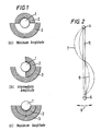
- the shells For minimum amplitude when both shells are in the form of semi-cylinders, the shells should be positioned in the least unbalanced position, i.e. with one facing the other. For maximum amplitude the shells should be positioned in the most unbalanced position, i.e. with the inner resting within the outer. For intermediate amplitudes the shells can be positioned between the extremes.
- the drill is suitable for use in drilling core samples for evaluating the mineral potential of deposits.
- variable amplitude rotor comprises a rotor shaft 1, a semi-cylindrical inner shell 2 and a semi-cylindrical outer shell 3.
- (a) shows the rotor arranged for minimum amplitude for oscillation, (b) for intermediate amplitude and (c) for maximum amplitude.
- the rotor assembly 4 is connected to a drill string 5 which in turn is connected to a core drilling shoe 6.
- the maximum out-of-balance oscillation is shown by line 7 and a reduced out-of-balance oscillation by line 8.
- the variable oscillation amplitude is shown by line 9.
- variable amplitude rotor 10 is contained within an oil filled housing 11 and mounted on a bearing pack 12.
- the rotor 10 is driven by a cable drive (not shown) through a connector 13 sealed from the housing by means of an oil seal 14.
- the housing 11 is clamped around a drill string 15 by means of a pivoted clamp 16.
Landscapes
- Engineering & Computer Science (AREA)
- Life Sciences & Earth Sciences (AREA)
- Geology (AREA)
- Mining & Mineral Resources (AREA)
- Physics & Mathematics (AREA)
- Environmental & Geological Engineering (AREA)
- Fluid Mechanics (AREA)
- General Life Sciences & Earth Sciences (AREA)
- Geochemistry & Mineralogy (AREA)
- Mechanical Engineering (AREA)
- Earth Drilling (AREA)
- Sampling And Sample Adjustment (AREA)
Applications Claiming Priority (2)
| Application Number | Priority Date | Filing Date | Title |
|---|---|---|---|
| GB8818024 | 1988-07-28 | ||
| GB888818024A GB8818024D0 (en) | 1988-07-28 | 1988-07-28 | Variable mass rotor |
Publications (2)
| Publication Number | Publication Date |
|---|---|
| EP0352979A2 true EP0352979A2 (fr) | 1990-01-31 |
| EP0352979A3 EP0352979A3 (fr) | 1992-02-05 |
Family
ID=10641276
Family Applications (1)
| Application Number | Title | Priority Date | Filing Date |
|---|---|---|---|
| EP19890307415 Withdrawn EP0352979A3 (fr) | 1988-07-28 | 1989-07-20 | Dispositif de forage à amplitude variable |
Country Status (4)
| Country | Link |
|---|---|
| EP (1) | EP0352979A3 (fr) |
| JP (1) | JPH0280785A (fr) |
| AU (1) | AU3884289A (fr) |
| GB (1) | GB8818024D0 (fr) |
Cited By (2)
| Publication number | Priority date | Publication date | Assignee | Title |
|---|---|---|---|---|
| EP0455994A3 (en) * | 1990-04-09 | 1992-01-02 | Bechem, Hannelore | Eccentric drive for radially oscillating rollers, rolling cutters and milling drilling tools |
| DE19732532A1 (de) * | 1997-07-29 | 1999-02-04 | Tracto Technik | Verfahren zum Richtungsbohren |
Family Cites Families (19)
| Publication number | Priority date | Publication date | Assignee | Title |
|---|---|---|---|---|
| DE932182C (de) * | 1953-07-16 | 1957-03-28 | Wolfgang Dr-Ing Herbold | Schwingendes Bohrverfahren |
| US3155163A (en) * | 1956-02-20 | 1964-11-03 | Jr Albert G Bodine | Method and apparatus for soinc jarring with reciprocating masss oscillator |
| US3217551A (en) * | 1962-03-21 | 1965-11-16 | Jr Albert G Bodine | Vibration generator for resonant loads and sonic systems embodying same |
| US3199614A (en) * | 1962-10-03 | 1965-08-10 | Jr Albert G Bodine | Sonic wave system for planting utility poles in the ground |
| US3289774A (en) * | 1965-07-14 | 1966-12-06 | Jr Albert G Bodine | Vibration isolator for sonic pole driving system |
| DE1634474A1 (de) * | 1966-02-24 | 1970-08-06 | Buckau Wolf Maschf R | Ruettelwalze |
| DE1558869A1 (de) * | 1967-05-19 | 1970-05-06 | Wissenschaftlich Tech Zentrum | Vibrationsgeraet zur Verdichtung von fein- und grobkoernigen Materialien |
| GB1183066A (en) * | 1967-06-02 | 1970-03-04 | Fyne Machinery & Eng | Improvements in and relating to the Driving of Piles, and more especially of Sheet Piling |
| US3734212A (en) * | 1971-08-20 | 1973-05-22 | Bucyrus Erie Co | Well drill and casing drive unit |
| US4073353A (en) * | 1976-03-22 | 1978-02-14 | Bodine Albert G | Sonic large bore earth auger |
| US4211121A (en) * | 1976-09-01 | 1980-07-08 | Fmc Corporation | Vibrator with eccentric weights |
| CS191531B1 (en) * | 1976-11-24 | 1979-07-31 | Stanislav Venc | Vibration compacting roller |
| US4176983A (en) * | 1978-07-17 | 1979-12-04 | Ingersoll-Rand Company | Variable eccentric device |
| BE894355A (nl) * | 1982-09-10 | 1983-01-03 | Callens Henri E | Triller met regelbare trilkracht |
| GB2152100B (en) * | 1983-12-20 | 1987-12-02 | Frederick William Wink | Vibratory drill apparatus |
| DE3515690C1 (de) * | 1985-05-02 | 1986-09-11 | Gebr. Lindenmeyer GmbH & Co Maschinenfabrik, 8906 Gersthofen | Vibrationsbaer mit Unwuchtverstellung |
| DE8530160U1 (de) * | 1985-09-05 | 1986-01-30 | Krings International GmbH & Co KG, 5138 Heinsberg | Vibrationsramme |
| GB8606711D0 (en) * | 1986-03-19 | 1986-04-23 | Andrews R D R | Vibratory machines |
| FR2639376A1 (fr) * | 1988-11-24 | 1990-05-25 | Albaret Travaux Publics Sa | Engin compacteur vibrant a amplitude modifiable |
-
1988
- 1988-07-28 GB GB888818024A patent/GB8818024D0/en active Pending
-
1989
- 1989-07-20 EP EP19890307415 patent/EP0352979A3/fr not_active Withdrawn
- 1989-07-21 AU AU38842/89A patent/AU3884289A/en not_active Abandoned
- 1989-07-27 JP JP19281589A patent/JPH0280785A/ja active Pending
Cited By (4)
| Publication number | Priority date | Publication date | Assignee | Title |
|---|---|---|---|---|
| EP0455994A3 (en) * | 1990-04-09 | 1992-01-02 | Bechem, Hannelore | Eccentric drive for radially oscillating rollers, rolling cutters and milling drilling tools |
| DE19732532A1 (de) * | 1997-07-29 | 1999-02-04 | Tracto Technik | Verfahren zum Richtungsbohren |
| DE19732532C2 (de) * | 1997-07-29 | 1999-10-28 | Tracto Technik | Verfahren und Vvorrichtung zum horizontalen Richtungsbohren |
| US6199643B1 (en) | 1997-07-29 | 2001-03-13 | Tracto-Technik Paul Schmidt Spezialmaschinen | Method and apparatus for directional boring |
Also Published As
| Publication number | Publication date |
|---|---|
| JPH0280785A (ja) | 1990-03-20 |
| GB8818024D0 (en) | 1988-09-01 |
| EP0352979A3 (fr) | 1992-02-05 |
| AU3884289A (en) | 1990-02-01 |
Similar Documents
| Publication | Publication Date | Title |
|---|---|---|
| US6129159A (en) | Vibratory drill head apparatus | |
| CN114555905B (zh) | 用于减少钻柱中的高频扭转振动的振动隔离联接器 | |
| US6851489B2 (en) | Method and apparatus for drilling wells | |
| CA1302117C (fr) | Systeme de mesure des charges exercees sur les trains de sonde et methode connexe | |
| US7730970B2 (en) | Drilling efficiency through beneficial management of rock stress levels via controlled oscillations of subterranean cutting levels | |
| US11519227B2 (en) | Vibration isolating coupler for reducing high frequency torsional vibrations in a drill string | |
| US4522271A (en) | Method and apparatus for damping vibrations in drill collar strings | |
| EP0352979A2 (fr) | Dispositif de forage à amplitude variable | |
| US12523141B2 (en) | Downhole tool with vibration dampening and/or shock absorption | |
| US6105712A (en) | Method for generating seismic shearing waves in a subterranean formation | |
| US4957175A (en) | Soil drilling equipment | |
| US5758539A (en) | Logging method and system for measuring mechanical parameters of the formations crossed through by a borehole | |
| GB2185508A (en) | Vibratory core drill apparatus | |
| US4715455A (en) | Drill shoe | |
| JPS6490391A (en) | All casing excavator and method of construction thereof | |
| RU2007543C1 (ru) | Способ шарошечного бурения скважин | |
| RU2059068C1 (ru) | Устройство для контроля угла наклона к плоскости горизонта турбобура при бурении горизонтальных скважин | |
| RU2206700C1 (ru) | Вибратор | |
| SU1763631A1 (ru) | Устройство дл бурени сопр женных скважин | |
| JP2531091Y2 (ja) | 海底コアサンプリング装置におけるコアバレル | |
| SU968225A1 (ru) | Устройство дл образовани скважин в грунте | |
| RU2135730C1 (ru) | Способ бурения скважины | |
| SU1609933A1 (ru) | Устройство дл бурени скважин | |
| SU1046461A1 (ru) | Буровой снар д | |
| CA2270128A1 (fr) | Systeme de forage sismique |
Legal Events
| Date | Code | Title | Description |
|---|---|---|---|
| PUAI | Public reference made under article 153(3) epc to a published international application that has entered the european phase |
Free format text: ORIGINAL CODE: 0009012 |
|
| AK | Designated contracting states |
Kind code of ref document: A2 Designated state(s): BE DE ES FR GB IT NL SE |
|
| PUAL | Search report despatched |
Free format text: ORIGINAL CODE: 0009013 |
|
| AK | Designated contracting states |
Kind code of ref document: A3 Designated state(s): BE DE ES FR GB IT NL SE |
|
| STAA | Information on the status of an ep patent application or granted ep patent |
Free format text: STATUS: THE APPLICATION IS DEEMED TO BE WITHDRAWN |
|
| 18D | Application deemed to be withdrawn |
Effective date: 19920806 |