EP0353066A1 - Stossbefestiger - Google Patents
Stossbefestiger Download PDFInfo
- Publication number
- EP0353066A1 EP0353066A1 EP89307650A EP89307650A EP0353066A1 EP 0353066 A1 EP0353066 A1 EP 0353066A1 EP 89307650 A EP89307650 A EP 89307650A EP 89307650 A EP89307650 A EP 89307650A EP 0353066 A1 EP0353066 A1 EP 0353066A1
- Authority
- EP
- European Patent Office
- Prior art keywords
- collar member
- collar
- fastener
- push
- side wall
- Prior art date
- Legal status (The legal status is an assumption and is not a legal conclusion. Google has not performed a legal analysis and makes no representation as to the accuracy of the status listed.)
- Granted
Links
- 230000013011 mating Effects 0.000 claims description 4
- 230000015572 biosynthetic process Effects 0.000 claims 1
- 239000002991 molded plastic Substances 0.000 abstract 1
- 238000009434 installation Methods 0.000 description 3
- 239000000463 material Substances 0.000 description 3
- 230000004075 alteration Effects 0.000 description 2
- 238000009413 insulation Methods 0.000 description 2
- 238000012986 modification Methods 0.000 description 2
- 230000004048 modification Effects 0.000 description 2
- 238000000465 moulding Methods 0.000 description 2
- 239000004033 plastic Substances 0.000 description 2
- 229920003023 plastic Polymers 0.000 description 2
- 239000004677 Nylon Substances 0.000 description 1
- 239000004698 Polyethylene Substances 0.000 description 1
- 229920001778 nylon Polymers 0.000 description 1
- -1 polyethylene Polymers 0.000 description 1
- 229920000573 polyethylene Polymers 0.000 description 1
Images

Classifications
-
- F—MECHANICAL ENGINEERING; LIGHTING; HEATING; WEAPONS; BLASTING
- F16—ENGINEERING ELEMENTS AND UNITS; GENERAL MEASURES FOR PRODUCING AND MAINTAINING EFFECTIVE FUNCTIONING OF MACHINES OR INSTALLATIONS; THERMAL INSULATION IN GENERAL
- F16B—DEVICES FOR FASTENING OR SECURING CONSTRUCTIONAL ELEMENTS OR MACHINE PARTS TOGETHER, e.g. NAILS, BOLTS, CIRCLIPS, CLAMPS, CLIPS OR WEDGES; JOINTS OR JOINTING
- F16B37/00—Nuts or like thread-engaging members
- F16B37/16—Wing-nuts
-
- F—MECHANICAL ENGINEERING; LIGHTING; HEATING; WEAPONS; BLASTING
- F16—ENGINEERING ELEMENTS AND UNITS; GENERAL MEASURES FOR PRODUCING AND MAINTAINING EFFECTIVE FUNCTIONING OF MACHINES OR INSTALLATIONS; THERMAL INSULATION IN GENERAL
- F16B—DEVICES FOR FASTENING OR SECURING CONSTRUCTIONAL ELEMENTS OR MACHINE PARTS TOGETHER, e.g. NAILS, BOLTS, CIRCLIPS, CLAMPS, CLIPS OR WEDGES; JOINTS OR JOINTING
- F16B37/00—Nuts or like thread-engaging members
- F16B37/08—Quickly-detachable or mountable nuts, e.g. consisting of two or more parts; Nuts movable along the bolt after tilting the nut
- F16B37/0807—Nuts engaged from the end of the bolt, e.g. axially slidable nuts
- F16B37/0842—Nuts engaged from the end of the bolt, e.g. axially slidable nuts fastened to the threaded bolt with snap-on-action, e.g. push-on nuts for stud bolts
-
- F—MECHANICAL ENGINEERING; LIGHTING; HEATING; WEAPONS; BLASTING
- F16—ENGINEERING ELEMENTS AND UNITS; GENERAL MEASURES FOR PRODUCING AND MAINTAINING EFFECTIVE FUNCTIONING OF MACHINES OR INSTALLATIONS; THERMAL INSULATION IN GENERAL
- F16B—DEVICES FOR FASTENING OR SECURING CONSTRUCTIONAL ELEMENTS OR MACHINE PARTS TOGETHER, e.g. NAILS, BOLTS, CIRCLIPS, CLAMPS, CLIPS OR WEDGES; JOINTS OR JOINTING
- F16B37/00—Nuts or like thread-engaging members
- F16B37/14—Cap nuts; Nut caps or bolt caps
Definitions
- the subject invention is directed toward the fastener art and, more particularly, to a push-on type fastener for use on threaded studs and the like.
- the invention is particularly suited for attaching decorative panels or insulation to a base frame having threaded studs welded thereon and will be described with particular reference to such use. As will become apparent, however, the invention is capable of broader application and could be used for attaching many different structures or components to bolts, studs and similar threaded elements.
- insulation and sound proofing materials must be installed on both horizontal and vertical panels.
- the installation is sometimes made by the use of nuts or similar fasteners received on threaded stud members welded to substructure or panels in the application area. It would be desirable in most instances if a push-on type fastener or nut could be used for such installation rather than a nut or fastener which must be rotatably threaded onto the threaded studs.
- the subject invention provides a push-on fastener which overcomes the noted problems and achieves an extremely high resistance to pull-ff.
- the fastener is, however, capable of being readily disconnected through a standard unthreading operation.
- the fastener of the invention can function well on standard 60° thread forms, but can also be readily adapted to a variety of other thread forms.
- the push-on fastener is arranged for connection to threaded studs or the like and comprises a first cylindrical collar member having first and second ends and a resilient side wall. Threads are formed on the interior of the resilient side wall in a form and size for positive engagement with the threads on the associated threaded stud.
- a second generally cylindrical collar member which has a relatively rigid side wall with first and second ends. The second collar member has an open interior diameter which is greater than the diameter of the first cylindrical collar member to permit the second collar member to be received over and surround the first collar member.
- Connecting means are provided for temporarily joining the second end of the first collar member to the second end of the second collar member with the collar members in axial alignment.
- Cooperating interengaging means are formed on the exterior of the resilient side wall of the first cylindrical collar member and the interior of the rigid side wall of the second collar member. These interengaging means act to prevent radial expansion of the first collar member while simultaneously preventing axial withdrawal of the second collar member in a direction off the second end of the first collar member after the second member has been moved from the temporarily connected position to a position received over and surrounding the first collar member.
- the resilient wall of the first collar member allows it to be readily pushed on over the end of the associated stud.
- the interengaging means interlock and act to prevent radial expansion or deflection of the first collar member thereby locking it firmly to the threaded stud. Because the thread form on the interior of the first collar member is arranged to correspond to the shape of the thread on the stud, a full positive engagement is achieved between the stud and the first collar member.
- the connecting means between the first and second collar members comprises a frangible web which maintains them in properly aligned position but which can break as the fastener is axially moved onto the associated threaded stud.
- the interengaging means between the exterior of the first collar member and the interior of the second collar member comprise cooperating thread forms with the threads on at least one of the two members being resilient and readily deflectable in a direction to allow the second collar member to be readily moved into position over the first collar member.
- the thread forms are preferably such that when the second collar member is in position, axial withdrawal is prevented and the two fastener collar components can be disconnected only by a standard unthreading operation.
- the first collar member can be removed from the associated stud either by an unthreading operation or a simple axial pull-off since it has an extremely resilient side wall and can readily deflect in radial directions except when the second collar member is in position.
- the second collar member preferably has a closed first end with a substantial radially extending head carried thereon.
- the enlarged head allows the second collar member to function in the nature of a nut or the like for retaining material in position on the threaded stud.
- a primary object of the subject invention is the provision of a push-on type of fastener which can function with a wide variety of threaded studs or the like and wherein the forces resisting pull-off of the fastener can be extremely high.
- Yet another object of the invention is the provision of a fastener of the type described which allows high resistance to pull-off to be achieved even when the threads on the associated threaded stud or the like have a shallow, widely spaced, and/or inconsistent thread form.
- Figures 1 through 4 illustrate the overall arrangement of a push-on type fastener 10 which is molded as an integral, one-piece structure from a suitable resinous plastic material such as nylon, polyethylene, or the like.
- the fastener 10 is designed to be received on the end of a threaded stud, rod, bolt or similar threaded or groove element with a simple axial push-on motion. That is, the fastener can be moved into its connected position merely by axially pushing the fastener onto the threaded element associated therewith.
- the fastener 10 comprises cooperating first and second generally cylindrical collar members 12 and 14, respectively.
- the collar member 12 includes a resilient, radially deflectable or expansible side wall 16 which extends from a first open end 18 to a second end 20.
- the radial flexibility and/or expansibility of the side wall 16 is enhanced by four vertically extending slots or openings 22.
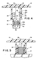
- the first collar member 12 is designed to be closely received over an associated threaded stud or the like 24 (see Figure 5). For this reason, the internal diameter of the central opening 26 of the collar member 12 is only slightly larger than the exterior diameter of the associated stud or bolt 24. Carried on the interior of the side wall 16 is a thread form 25 which is sized and shaped to closely mate with threads on the stud or bolt 24.
- the radial flexibility or expansibility of the first collar 12 allows it to be placed on the associated stud or bolt 24 by a simple axial pushing action.
- the same radial flexibility allows the first collar to be readily removed from the stud by a simple axial pull-off operation.
- the second collar member 14 is arranged to function in a manner to prevent radial expansion of the first collar member 12 after it has been installed in position on the associated threaded stud. Consequently, the second collar member 14 has a relatively rigid side wall 30 which is also of generally cylindrical configuration. Access openings 31 are formed through diagonally opposite sides of the wall 30. These openings result from the tooling used in molding the fastener and form no part of the invention.
- a central opening 32 extends axially of the collar 14 and the side wall 30.
- the opening 32 is sized to relatively closely receive collar 12.
- the first or upper end of the side wall 30 is generally closed by an enlarged radially extending head member 34.
- the head member 34 could have a variety of designs or configurations or comprise a separate element or assembly such as a pipe or wire holder depending upon the intended use for the fastener 10.
- the head 34 includes a transversely extending slot 36 adapted to receive a screw driver or the like.
- first and second collar members 12, 14, respectively are joined at their respective second ends in a manner to permit them to at least temporarily retain the aligned position illustrated in Figure 4.
- the connecting means comprise a thin radially extending web of plastic 40 which is molded in place simultaneously with the molding of the fastener 10.
- the web 40 is sized and arranged such that after tne first collar member 12 has been moved into position on the end of the threaded stud as shown in Figure 5,further axial force applied to the second collar member 14 causes the web to break and the member 14 to move into located position over the collar 12 as shown in Figure 5.
- the two collar members are provided with cooperating interengaging means.
- the interengaging means of the invention could have many designs but in the subject embodiment comprise cooperating thread forms which are generally of the type shown and described in the commonly assigned U. S. Patent 4,756,654 which is incorporated herein by reference.
- the exterior of the collar member 12 is provided with a first continuous spiral of threads 42 which preferably have somewhat of a buttress shape with a generally horizontal first wall 42a and an inclined mating wall 42b (See Figure 4).
- the interior of the collar member 14 is provided with a continuous cooperating thread form in the configuration best shown in Figures 1 and 4.
- the threads 46 formed on the interior of the side walls 30 are relatively resilient and are inclined in a direction away from the second or lower end of the opening 32.
- these resilient finger like threads is more fully described and shown in the aforementioned commonly assigned U. S. Patent.
- they include a first face 46a which is inclined somewhere in the range of approximately 30° relative to the axis of the fastener.
- a second wall 46b inclined at an angle in the range of approximately 45° joins wall 46a at the apex of the thread form. The arrangement allows the threads to readily flex in a direction away from the lower end of the fastener.
- the subject fastener has the ability to work on standard thread forms and produce a high resistance to pull-off.
- the fastener can be molded in one piece and after installation can be removed by a simple unthreading operation. Further, the individual components of the fastener can be separated to facilitate subsequent serviceability of the assembly.
Landscapes
- Engineering & Computer Science (AREA)
- General Engineering & Computer Science (AREA)
- Mechanical Engineering (AREA)
- Snaps, Bayonet Connections, Set Pins, And Snap Rings (AREA)
- Dowels (AREA)
- Connection Of Plates (AREA)
- Mutual Connection Of Rods And Tubes (AREA)
- Separation Using Semi-Permeable Membranes (AREA)
Applications Claiming Priority (2)
| Application Number | Priority Date | Filing Date | Title |
|---|---|---|---|
| US07/225,041 US4850778A (en) | 1988-07-27 | 1988-07-27 | Push-on fastener |
| US225041 | 1988-07-27 |
Publications (2)
| Publication Number | Publication Date |
|---|---|
| EP0353066A1 true EP0353066A1 (de) | 1990-01-31 |
| EP0353066B1 EP0353066B1 (de) | 1992-11-19 |
Family
ID=22843275
Family Applications (1)
| Application Number | Title | Priority Date | Filing Date |
|---|---|---|---|
| EP89307650A Expired - Lifetime EP0353066B1 (de) | 1988-07-27 | 1989-07-27 | Stossbefestiger |
Country Status (6)
| Country | Link |
|---|---|
| US (1) | US4850778A (de) |
| EP (1) | EP0353066B1 (de) |
| JP (1) | JP2842625B2 (de) |
| KR (1) | KR0141375B1 (de) |
| DE (1) | DE68903541T2 (de) |
| ES (1) | ES2036347T3 (de) |
Cited By (1)
| Publication number | Priority date | Publication date | Assignee | Title |
|---|---|---|---|---|
| DE4334926A1 (de) * | 1993-10-13 | 1995-04-20 | United Carr Gmbh Trw | Verbindungselement aus Kunststoff |
Families Citing this family (60)
| Publication number | Priority date | Publication date | Assignee | Title |
|---|---|---|---|---|
| JPH0743474Y2 (ja) * | 1990-05-09 | 1995-10-09 | ポップリベット・ファスナー株式会社 | 板状部材取付け用クリップ |
| JPH04114107U (ja) * | 1991-03-27 | 1992-10-07 | ポツプリベツト・フアスナー株式会社 | パネルクリツプ |
| US5197840A (en) * | 1991-04-03 | 1993-03-30 | Illinois Tool Works Inc. | Insulation retainer |
| AT402223B (de) * | 1994-11-24 | 1997-03-25 | Hkt Haider & Deravis Gmbh | Mutter für eine befestigungseinrichtung |
| US5542799A (en) * | 1994-12-02 | 1996-08-06 | Agora Enterprises, L.L.P. | Machine screw |
| US5642973A (en) * | 1995-12-26 | 1997-07-01 | Pretty; Daniel Glenn | Plumbing cleanout cover |
| WO1998048182A1 (de) | 1997-04-17 | 1998-10-29 | Emhart Inc. | Montagesystem mit befestigungsbolzen und verfahren zur ausbildung eines montagesystems |
| DE19812367A1 (de) * | 1997-04-17 | 1998-10-22 | Emhart Inc | Montagesystem mit Befestigungsbolzen und Verfahren zur Ausbildung eines Montagesystems |
| US5871320A (en) * | 1997-12-29 | 1999-02-16 | Emhart Inc. | Insulation retainer |
| US6179539B1 (en) * | 1999-09-09 | 2001-01-30 | Illinois Tool Works Inc. | Locking clip with moveable collet |
| US6235073B1 (en) * | 1999-11-10 | 2001-05-22 | Nelson Industries, Inc. | Fastener retention system |
| NL1014082C2 (nl) * | 2000-01-17 | 2001-07-18 | Franciscus Antonius Maria Van | Systeem voor het verbinden van elementen. |
| US6505386B1 (en) * | 2001-07-25 | 2003-01-14 | Daimlerchrysler Corporation | Grommet—wire harness retainer |
| US6764351B2 (en) * | 2001-08-27 | 2004-07-20 | Campagnie Deutsch GmbH | Electrical connector |
| US7222460B2 (en) * | 2002-07-17 | 2007-05-29 | Dayton Superior Corporation | Cover for a concrete construction |
| DE10357024A1 (de) * | 2003-12-03 | 2005-06-30 | Newfrey Llc, Newark | Befestigungselement zur Anbringung auf einem Gewindebolzen |
| US20050008456A1 (en) * | 2003-06-18 | 2005-01-13 | Ejot Gmbh & Co. Kg | Device for securing a structural element to a panel-like component |
| US7090454B2 (en) * | 2003-07-24 | 2006-08-15 | Floyd Bell, Inc. | Ratchet interlocking housing |
| US7455192B2 (en) | 2004-11-03 | 2008-11-25 | Illinois Tool Works Inc. | Overmolded adhesive hole plug |
| JP4850573B2 (ja) * | 2006-04-24 | 2012-01-11 | ポップリベット・ファスナー株式会社 | アンダーカバー等の固定具及び取付装置 |
| US8251626B1 (en) | 2007-02-21 | 2012-08-28 | Jose Gonzalez | Bolt and receiver for adaptively attaching to surfaces |
| JP2009030707A (ja) * | 2007-07-26 | 2009-02-12 | Nippon Pop Rivets & Fasteners Ltd | クリップ |
| US20090293389A1 (en) * | 2007-10-17 | 2009-12-03 | High Industries, Inc. | Cover for prestressed concrete member |
| US20090100768A1 (en) * | 2007-10-17 | 2009-04-23 | High Industries, Inc. | Cover for prestressed concrete member |
| GB0804196D0 (en) * | 2008-03-06 | 2008-04-16 | Newfrey Llc | Fastener for automotive components |
| DE102008036610A1 (de) * | 2008-08-06 | 2010-02-11 | Ejot Baubefestigungen Gmbh | Teleskophülse |
| US7985042B1 (en) | 2008-10-31 | 2011-07-26 | Fourslides Inc. | Thread cage retainer |
| EP2299011A1 (de) * | 2009-09-18 | 2011-03-23 | KERAMAG Keramische Werke Aktiengesellschaft | Befestigungsvorrichtung für einen Sanitärausstattungsgegenstand |
| US8959730B2 (en) * | 2009-09-24 | 2015-02-24 | A. Raymond Et Cie | Push-on clip fastener |
| JP5824031B2 (ja) * | 2010-04-02 | 2015-11-25 | イリノイ トゥール ワークス インコーポレイティド | 防振用の車両取り付けアセンブリ |
| DE102010024870A1 (de) * | 2010-06-22 | 2011-12-22 | Illinois Tool Works Inc. | Vorrichtung zum Befestigen eines Bauteils an einem Befestigungsbolzen |
| JP5558576B2 (ja) * | 2010-09-24 | 2014-07-23 | Ykk株式会社 | 固定具、ロックシステム及び固定対象物の固定方法 |
| ES2628121T3 (es) * | 2011-12-29 | 2017-08-01 | Itw Fastener Products Gmbh | Tuerca elástica |
| JP5978541B2 (ja) * | 2012-08-15 | 2016-08-24 | ポップリベット・ファスナー株式会社 | スタッド係止具 |
| DE102013005830A1 (de) * | 2013-04-04 | 2014-10-09 | Iwis Motorsysteme Gmbh & Co. Kg | Gleitschiene zum Spannen und Führen eines Endlostriebmittels und Verfahren zum Herstellen der Gleitschiene |
| US9618029B2 (en) | 2013-09-23 | 2017-04-11 | The Boeing Company | Systems and methods for use in covering a portion of a fastener protruding from a surface |
| US9541118B2 (en) * | 2013-09-23 | 2017-01-10 | The Boeing Company | Systems and methods for use in covering a portion of a fastener protruding from a surface |
| US9470257B2 (en) * | 2014-04-17 | 2016-10-18 | Nmc Group, Inc. | Fastener assembly for insulation blanket |
| DE102014009410B4 (de) * | 2014-06-25 | 2018-04-05 | Audi Ag | Verfahren zum Verbinden eines Einpressbolzens mit einem ein Vorloch aufweisenden Blechteil und Abdeckelement zur Durchführung des Verfahrens |
| JP6240060B2 (ja) * | 2014-12-18 | 2017-11-29 | トヨタ自動車株式会社 | 被保持部材の仮止め具および保持具 |
| FR3032223B1 (fr) * | 2015-02-03 | 2017-02-10 | Snecma | Bouchon anti-corrosion pour combler un orifice de fixation et systeme comprenant ledit bouchon |
| CN107795559B (zh) * | 2016-09-06 | 2021-03-09 | 福特环球技术公司 | 用于车辆地毯的固定件 |
| EP3392418B1 (de) * | 2017-04-19 | 2020-04-29 | Geberit International AG | Befestigungssystem |
| US10655667B2 (en) * | 2017-09-28 | 2020-05-19 | The Boeing Company | Rapid installation thermoplastic EME protection cap |
| DE102018104360A1 (de) * | 2018-02-27 | 2019-08-29 | Airbus Operations Gmbh | Befestigungssystem zum Sichern von Bauteilen |
| US10962043B2 (en) | 2018-04-24 | 2021-03-30 | The Boeing Company | Anchoring nut for an EME protection cap system |
| US10920818B2 (en) | 2018-04-27 | 2021-02-16 | The Boeing Company | Anchoring washer for an EME protection cap system |
| JP6869924B2 (ja) * | 2018-07-23 | 2021-05-12 | ポップリベット・ファスナー株式会社 | スタッド係止具 |
| US10948004B2 (en) | 2018-07-26 | 2021-03-16 | The Boeing Company | Anchoring bolt head for an EME protection cap system |
| USD871892S1 (en) * | 2018-09-27 | 2020-01-07 | B. Erickson Manufacturing Ltd. | Rotatable e-track |
| US11248647B2 (en) | 2018-11-09 | 2022-02-15 | The Boeing Company | EME cap for preventing uncured sealant squeeze out |
| US10989244B2 (en) | 2018-11-20 | 2021-04-27 | The Boeing Company | EME protection cap system with push sealant extrusion mechanism |
| CA3121969C (en) | 2018-12-03 | 2025-05-27 | Saint-Gobain Performance Plastics Pampus Gmbh | PRESSURE FASTENER, ASSEMBLY, AND ASSOCIATED MANUFACTURING AND USE METHOD |
| USD883071S1 (en) * | 2018-12-18 | 2020-05-05 | Railblaza Limited | Support for boating accessories |
| US10982704B2 (en) | 2019-01-03 | 2021-04-20 | The Boeing Company | EME protection cap system with screw sealant mechanism |
| US11236777B2 (en) | 2019-05-06 | 2022-02-01 | The Boeing Company | Friction fit electromagnetic effect protection cap system |
| US11788573B2 (en) | 2019-05-23 | 2023-10-17 | The Boeing Company | Multi-component melt electromagnetic effect protection cap system |
| US11754111B2 (en) | 2020-03-16 | 2023-09-12 | The Boeing Company | Compression fit EME protection seal cap |
| US12018711B1 (en) * | 2023-06-15 | 2024-06-25 | Edwin Ingalls | Two-piece fastener |
| US12104634B1 (en) | 2023-06-15 | 2024-10-01 | Edwin Ingalls | Two-piece fastener |
Citations (5)
| Publication number | Priority date | Publication date | Assignee | Title |
|---|---|---|---|---|
| DE1475035A1 (de) * | 1965-12-01 | 1969-04-24 | Hellermann Gmbh P | Befestigungselementpaar |
| GB1280834A (en) * | 1968-10-02 | 1972-07-05 | Ft Products Ltd | Stud and socket fastenings |
| DE2736012A1 (de) * | 1976-08-16 | 1978-02-23 | Nifco Inc | Befestiger zur befestigung eines teils an plattenmaterial |
| GB2077845A (en) * | 1980-06-16 | 1981-12-23 | Illinois Tool Works | Plastics Drive Fasteners |
| US4756654A (en) * | 1984-06-13 | 1988-07-12 | Trw Inc. | Fastening device |
Family Cites Families (13)
| Publication number | Priority date | Publication date | Assignee | Title |
|---|---|---|---|---|
| US3910156A (en) * | 1974-06-12 | 1975-10-07 | Illinois Tool Works | Screw anchor clip |
| JPS5610811A (en) * | 1979-07-06 | 1981-02-03 | Nifco Inc | Locking equipment |
| JPS602334Y2 (ja) * | 1980-07-15 | 1985-01-23 | 株式会社ニフコ | ナツト |
| US4460298A (en) * | 1981-06-03 | 1984-07-17 | Illinois Tool Works Inc. | Self retaining threaded screw grommet |
| DE3327751A1 (de) * | 1982-08-06 | 1984-02-09 | Avdel Ltd., Welwyn Garden City, Hertfordshire | Verankerungsmutter-befestigungsvorrichtung |
| US4579493A (en) * | 1982-08-27 | 1986-04-01 | Usm Corporation | Push button for Christmas tree stud |
| US4521148A (en) * | 1983-05-06 | 1985-06-04 | Nifco Inc. | Hinged mirror image plastic fastener for quick assembly to threaded male members |
| DE3325686A1 (de) * | 1983-07-15 | 1985-01-24 | Tucker Gmbh, 6300 Giessen | Halteklammer |
| US4600344A (en) * | 1983-12-05 | 1986-07-15 | Illinois Tool Works Inc. | Push-on plastic wing-nut fastener |
| US4571136A (en) * | 1984-02-10 | 1986-02-18 | Illinois Tool Works Inc. | Plastic push-on fastener |
| JPS6272910A (ja) * | 1985-09-27 | 1987-04-03 | 株式会社ニフコ | ネジ受け具 |
| JPS6293508A (ja) * | 1985-10-16 | 1987-04-30 | 株式会社 東郷製作所 | 留め具 |
| JPH0353046Y2 (de) * | 1987-01-23 | 1991-11-19 |
-
1988
- 1988-07-27 US US07/225,041 patent/US4850778A/en not_active Expired - Fee Related
-
1989
- 1989-07-27 JP JP1195393A patent/JP2842625B2/ja not_active Expired - Fee Related
- 1989-07-27 ES ES198989307650T patent/ES2036347T3/es not_active Expired - Lifetime
- 1989-07-27 EP EP89307650A patent/EP0353066B1/de not_active Expired - Lifetime
- 1989-07-27 KR KR1019890010606A patent/KR0141375B1/ko not_active Expired - Fee Related
- 1989-07-27 DE DE8989307650T patent/DE68903541T2/de not_active Expired - Fee Related
Patent Citations (5)
| Publication number | Priority date | Publication date | Assignee | Title |
|---|---|---|---|---|
| DE1475035A1 (de) * | 1965-12-01 | 1969-04-24 | Hellermann Gmbh P | Befestigungselementpaar |
| GB1280834A (en) * | 1968-10-02 | 1972-07-05 | Ft Products Ltd | Stud and socket fastenings |
| DE2736012A1 (de) * | 1976-08-16 | 1978-02-23 | Nifco Inc | Befestiger zur befestigung eines teils an plattenmaterial |
| GB2077845A (en) * | 1980-06-16 | 1981-12-23 | Illinois Tool Works | Plastics Drive Fasteners |
| US4756654A (en) * | 1984-06-13 | 1988-07-12 | Trw Inc. | Fastening device |
Cited By (1)
| Publication number | Priority date | Publication date | Assignee | Title |
|---|---|---|---|---|
| DE4334926A1 (de) * | 1993-10-13 | 1995-04-20 | United Carr Gmbh Trw | Verbindungselement aus Kunststoff |
Also Published As
| Publication number | Publication date |
|---|---|
| DE68903541D1 (de) | 1992-12-24 |
| KR0141375B1 (ko) | 1998-07-01 |
| US4850778A (en) | 1989-07-25 |
| KR900001464A (ko) | 1990-02-27 |
| EP0353066B1 (de) | 1992-11-19 |
| JPH02118213A (ja) | 1990-05-02 |
| DE68903541T2 (de) | 1993-05-19 |
| JP2842625B2 (ja) | 1999-01-06 |
| ES2036347T3 (es) | 1993-05-16 |
Similar Documents
| Publication | Publication Date | Title |
|---|---|---|
| US4850778A (en) | Push-on fastener | |
| EP1143157B1 (de) | Wasserdichte Halteöse | |
| AU638227B2 (en) | A plug | |
| US4756654A (en) | Fastening device | |
| US5820323A (en) | Weld-on fastener, welding equipment for the welding of the fastener, and arrangement for the fastening of an assembly part to the weldable fastener | |
| JP3652757B2 (ja) | フアスナ構体用ナット | |
| US3345899A (en) | Synthetic resin fasteners | |
| US4798507A (en) | Sheet metal U-nut | |
| US5302066A (en) | Locking fastener | |
| US5419650A (en) | Stabilized pipe fastener using an expandable sleeve | |
| AU581387B2 (en) | Fastening device | |
| US4420859A (en) | Two-part panel fastener | |
| JP2000266031A (ja) | ボルトとスリーブのアセンブリ | |
| CA1041886A (en) | Self-sealing, self-locking threaded fastener | |
| GB2167801A (en) | Wire gripper | |
| US5219255A (en) | Mechanically locked nut assembly | |
| EP0804688B1 (de) | Blindniet und blindnietverfahren | |
| JPH0733844B2 (ja) | 締め具構成要素 | |
| GB2136076A (en) | Fastener | |
| US7621707B2 (en) | Fastener | |
| EP0698742B1 (de) | Drehbarer Karabinerhaken | |
| EP1083341B1 (de) | Bewegbare Sicherungsmutter | |
| EP3325823A1 (de) | Befestigungsmittel und befestigungssystem für weiche materialien | |
| US4762450A (en) | Damage resistant plastic expansion nut and screw therefor | |
| US5078561A (en) | Plastic expansion nut |
Legal Events
| Date | Code | Title | Description |
|---|---|---|---|
| PUAI | Public reference made under article 153(3) epc to a published international application that has entered the european phase |
Free format text: ORIGINAL CODE: 0009012 |
|
| AK | Designated contracting states |
Kind code of ref document: A1 Designated state(s): DE ES FR GB IT SE |
|
| 17P | Request for examination filed |
Effective date: 19900730 |
|
| 17Q | First examination report despatched |
Effective date: 19910222 |
|
| GRAA | (expected) grant |
Free format text: ORIGINAL CODE: 0009210 |
|
| AK | Designated contracting states |
Kind code of ref document: B1 Designated state(s): DE ES FR GB IT SE |
|
| PG25 | Lapsed in a contracting state [announced via postgrant information from national office to epo] |
Ref country code: IT Free format text: LAPSE BECAUSE OF FAILURE TO SUBMIT A TRANSLATION OF THE DESCRIPTION OR TO PAY THE FEE WITHIN THE PRE;WARNING: LAPSES OF ITALIAN PATENTS WITH EFFECTIVE DATE BEFORE 2007 MAY HAVE OCCURRED AT ANY TIME BEFORE 2007. THE CORRECT EFFECTIVE DATE MAY BE DIFFERENT FROM THE ONE RECORDED.SCRIBED TIME-LIMIT Effective date: 19921119 |
|
| REF | Corresponds to: |
Ref document number: 68903541 Country of ref document: DE Date of ref document: 19921224 |
|
| ET | Fr: translation filed | ||
| REG | Reference to a national code |
Ref country code: ES Ref legal event code: FG2A Ref document number: 2036347 Country of ref document: ES Kind code of ref document: T3 |
|
| PLBE | No opposition filed within time limit |
Free format text: ORIGINAL CODE: 0009261 |
|
| STAA | Information on the status of an ep patent application or granted ep patent |
Free format text: STATUS: NO OPPOSITION FILED WITHIN TIME LIMIT |
|
| 26N | No opposition filed | ||
| EAL | Se: european patent in force in sweden |
Ref document number: 89307650.5 |
|
| PGFP | Annual fee paid to national office [announced via postgrant information from national office to epo] |
Ref country code: GB Payment date: 19960617 Year of fee payment: 8 |
|
| PGFP | Annual fee paid to national office [announced via postgrant information from national office to epo] |
Ref country code: SE Payment date: 19960624 Year of fee payment: 8 |
|
| PGFP | Annual fee paid to national office [announced via postgrant information from national office to epo] |
Ref country code: ES Payment date: 19960715 Year of fee payment: 8 Ref country code: FR Payment date: 19960715 Year of fee payment: 8 |
|
| PGFP | Annual fee paid to national office [announced via postgrant information from national office to epo] |
Ref country code: DE Payment date: 19960730 Year of fee payment: 8 |
|
| PG25 | Lapsed in a contracting state [announced via postgrant information from national office to epo] |
Ref country code: GB Free format text: LAPSE BECAUSE OF NON-PAYMENT OF DUE FEES Effective date: 19970727 |
|
| PG25 | Lapsed in a contracting state [announced via postgrant information from national office to epo] |
Ref country code: SE Effective date: 19970728 Ref country code: ES Free format text: LAPSE BECAUSE OF THE APPLICANT RENOUNCES Effective date: 19970728 |
|
| GBPC | Gb: european patent ceased through non-payment of renewal fee |
Effective date: 19970727 |
|
| PG25 | Lapsed in a contracting state [announced via postgrant information from national office to epo] |
Ref country code: FR Free format text: LAPSE BECAUSE OF NON-PAYMENT OF DUE FEES Effective date: 19980331 |
|
| PG25 | Lapsed in a contracting state [announced via postgrant information from national office to epo] |
Ref country code: DE Free format text: LAPSE BECAUSE OF NON-PAYMENT OF DUE FEES Effective date: 19980401 |
|
| EUG | Se: european patent has lapsed |
Ref document number: 89307650.5 |
|
| REG | Reference to a national code |
Ref country code: FR Ref legal event code: ST |
|
| REG | Reference to a national code |
Ref country code: ES Ref legal event code: FD2A Effective date: 20001009 |