EP0353074A2 - Linearantrieb - Google Patents
Linearantrieb Download PDFInfo
- Publication number
- EP0353074A2 EP0353074A2 EP89307662A EP89307662A EP0353074A2 EP 0353074 A2 EP0353074 A2 EP 0353074A2 EP 89307662 A EP89307662 A EP 89307662A EP 89307662 A EP89307662 A EP 89307662A EP 0353074 A2 EP0353074 A2 EP 0353074A2
- Authority
- EP
- European Patent Office
- Prior art keywords
- magnetic
- yoke
- moving units
- linear actuator
- moving
- Prior art date
- Legal status (The legal status is an assumption and is not a legal conclusion. Google has not performed a legal analysis and makes no representation as to the accuracy of the status listed.)
- Granted
Links
Images


Classifications
-
- H—ELECTRICITY
- H02—GENERATION; CONVERSION OR DISTRIBUTION OF ELECTRIC POWER
- H02P—CONTROL OR REGULATION OF ELECTRIC MOTORS, ELECTRIC GENERATORS OR DYNAMO-ELECTRIC CONVERTERS; CONTROLLING TRANSFORMERS, REACTORS OR CHOKE COILS
- H02P1/00—Arrangements for starting electric motors or dynamo-electric converters
-
- H—ELECTRICITY
- H01—ELECTRIC ELEMENTS
- H01F—MAGNETS; INDUCTANCES; TRANSFORMERS; SELECTION OF MATERIALS FOR THEIR MAGNETIC PROPERTIES
- H01F7/00—Magnets
- H01F7/06—Electromagnets; Actuators including electromagnets
- H01F7/08—Electromagnets; Actuators including electromagnets with armatures
- H01F7/14—Pivoting armatures
-
- H—ELECTRICITY
- H01—ELECTRIC ELEMENTS
- H01F—MAGNETS; INDUCTANCES; TRANSFORMERS; SELECTION OF MATERIALS FOR THEIR MAGNETIC PROPERTIES
- H01F7/00—Magnets
- H01F7/06—Electromagnets; Actuators including electromagnets
- H01F7/08—Electromagnets; Actuators including electromagnets with armatures
- H01F7/16—Rectilinearly-movable armatures
- H01F7/1638—Armatures not entering the winding
- H01F7/1646—Armatures or stationary parts of magnetic circuit having permanent magnet
-
- H—ELECTRICITY
- H02—GENERATION; CONVERSION OR DISTRIBUTION OF ELECTRIC POWER
- H02K—DYNAMO-ELECTRIC MACHINES
- H02K7/00—Arrangements for handling mechanical energy structurally associated with dynamo-electric machines, e.g. structural association with mechanical driving motors or auxiliary dynamo-electric machines
- H02K7/06—Means for converting reciprocating motion into rotary motion or vice versa
- H02K7/065—Electromechanical oscillators; Vibrating magnetic drives
-
- H—ELECTRICITY
- H01—ELECTRIC ELEMENTS
- H01F—MAGNETS; INDUCTANCES; TRANSFORMERS; SELECTION OF MATERIALS FOR THEIR MAGNETIC PROPERTIES
- H01F7/00—Magnets
- H01F7/06—Electromagnets; Actuators including electromagnets
- H01F7/08—Electromagnets; Actuators including electromagnets with armatures
- H01F7/121—Guiding or setting position of armatures, e.g. retaining armatures in their end position
- H01F7/122—Guiding or setting position of armatures, e.g. retaining armatures in their end position by permanent magnets
Definitions
- the present invention relates to a step linear actuator which makes linear motion using electromechanical conversion means.
- a linear motor or a linear pulse motor is known as a means of directly driving a driven member without using the above conversion mechanism.
- These driving apparatuses are composed of a stator comprising mainly magnetic materials and forming a traveling path and a mover disposed opposite to said stator in a slight gap.
- the above stator is composed of magnetic pole teeth of a certain pitch
- the mover is composed of a pair of yokes having different pitches from that of the magnetic pole teeth of the stator and holding a permanent magnet therebetween and a pair of the electromagnetic coils wound on the yokes.
- the mover is displaced stepwise to the stator by alternate excitation of the electromagnetic coils.
- the suspension of the mover makes it difficult to keep stability to the traveling path due to the vibration and impact exerted from the exterior of the apparatus and the positional condition.
- the armatures By alternately exciting a pair of electromagnetic coils contained in the stators, the armatures are attracted to the stator side against the pressing force of the spring means, and, in collaboration with said armatures, the latching means on the disk performs pivotal movement at the fulcrum of pivotal movement at its end, so that the shaft is gripped with said center opening, by which linear movement is performed.
- This construction necessitates a mechanical grip means besides the electromagnetically operating means, requiring a large number of component, with increase in size and cost, and further, due to mechanical grip of the shaft, wear occurs, thereby providing problems in reliability and precision of the apparatus.
- An object of the present invention is to provide a linear actuator which can be constructed easily in a small size at a reduced cost, and has high productivity.
- a linear actuator of the present invention comprises; a stationary member composed of a magnetic material and having a traveling path; first and second moving units which are supported in contact with said stationary member by respective magnetic coupling means and which face each other at respective opposing faces displaceably relative to each other in a prescribed stroke; and magnetic drive means which cooperates with said first and second moving units for generating an electromagnetic force at the opposing faces to move one of said first and second moving units.
- the first and second moving units are at all times magnetically coupled with the stationary member by magnetic fluxes formed by the magnetic coupling means while no electric current is let flow.
- a magnetic flux path is so constructed that, by letting an electric current flow through the magnetic drive means, an electromagnetic force is generated between the opposing faces to cause a relative displacement of the first and second moving units in the attracting direction at a prescribed stroke, and that the magnetic flux for generating the electromagnetic force is let flow between the respective moving units and the stationary member to overlap the magnetic flux of the magnetic coupling means at the contact part of each moving unit with the stationary member so that the magnetic coupling force with the stationary member either increases or decreases.
- each contact force of the first and second moving units with the stationary member is selectively controlled one in the more strengthening direction and the other in the more weakening direction so that one of the moving units is held stationary on the stationary member and the other makes a step movement by the electromagnetic force acting between the opposing faces of the moving units.
- the first moving unit has opposing faces at opposite sides in the moving direction of the moving units
- the second moving unit has opposing faces opposing the opposing faces of the first moving unit to form first and second gaps at opposite sides in the moving direction of the moving units.
- First and second electromagnetic means are provided for generating magnetic fluxes passing through the first and second gaps, respectively.
- each moving unit is at all times stably carried in contact with the stationary member by the magnetic coupling means of simple construction such as a permanent magnet, and moreover, all the drive members allowing to obtain relatively the prescribed stroke are housed in the first and second moving units, without necessitating any special rail such as projected magnetic pole teeth on the stationary member which forms a traveling path. Accordingly, a simple, compact drive apparatus having as a whole small number of parts can be realized.
- the cost of the whole apparatus can be low, so that the linear actuator has high productivity.
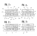
- Figs. 1, 2 and 3 show a step linear actuator according to a first embodiment of the present invention.
- the linear actuator comprises a stationary baseplate 10 and a pair of moving units 20, 40 which are in contact with said baseplate and are relatively freely displaceable at a prescribed stroke in the direction of advance to each other.
- the moving unit 20 has a one-side opened square shaped yoke 21 which is in contact with the stationary baseplate 10 in a positional relationship of crossing at right angles therewith at a pair of contact faces 21a, 21b, a yoke 24 which opposes at an end face 24a thereof to the stationary baseplate 10 via a certain gap therebetween at about the middle between said contact faces 21a, 21b, and a permanent magnet 25 which is clamped at two end faces thereof having different magnetic poles by said yokes 21 and 24 at about the central lower part of the yoke 21.
- the moving unit 24 has a one-side opened square shaped yoke 41 having contact faces 41a, 41b which are in contact with the stationary baseplate 10 in the direction of advance, a one-side opened square shaped yoke 43 having two end faces 43a, 43b which are disposed symmetrically and at right angles with the contact faces 41a, 41b and each of which opposes via a certain gap to the stationary baseplate 10, and a permanent magnet 42 which is clamped at two end faces thereof having different magnetic poles by said yokes 41 and 43 at around the central lower part of the yoke 43.
- the yokes and the stationary baseplate 10 which form the magnetic flux paths of the respective moving units 20, 40 are mainly composed of a magenetic material comprising a low-carbon steel, and the permanent magnets 25, 42 are magnetized so that the same magnetic poles are formed at the yoke end face 24a of the moving unit 20 and the yoke end faces 43a, 43b of the moving unit 40.
- the permanent magnets, the yokes and the stationary baseplate constitute magnetic coupling means.
- yokes 22 and 23 coupled with the yoke 21 each having a square section.
- the yokes 22 and 23 are projecting in parallel with the stationary baseplate 10 in bi-directions respectively along the direction of advance, centering on the contact faces 21a, 21b of the moving unit 20, and oppose through a slight gap to the inner face 41c of the yoke 41 which is vertically positioned to the stationary baseplate 10 at its one yoke end face 22a and to the inner face 41d at its another yoke end 23a, thereby constituting respective opposing faces of the moving units 20, 40.
- the projecting yokes 22, 23 of the moving unit 20 there are fitted a pair of electromagnetic coils 30, 32 wound on coil bobbins 31, 32 formed of resin molding having a square center opening.
- the electromagnetic coils 30, 32 utilized as sources of magnetomotive forces, for example, assuming the electro-magnetic coil 30 to be a source of a magnetomotive force, a magnetic flux path is formed such that a constant magnetic flux flows to the yoke 41, contact faces 41a, 41b, stationary baseplate 10, contact faces 21a, 21b and yoke 21 through a gap between the yoke end face 22a and the yoke 41c.
- each yoke forming the magnetic flux path and the electromagnetic coils 30, 32 constitute a magnetic drive means.
- the stationary baseplate 10 is fixed to an apparatus body which utilizes the linear actuator of the present embodiment as a drive device.
- the guide member 15 has a guide face 15a which is perpendicular to the surface of the stationary baseplate 10 and a control face 15b which is parallel therewith.
- the guide face 15a guides the lower side face 44a of the yoke 41 of the moving unit 40.
- the guide face 15b is disposed opposite to the upper face 44b of the lower part of the yoke 41. By this, control is made such that the moving unit 40 is not released from the stationary baseplate 10.
- the guide member 16 also guides the lower side face of the moving unit 40.
- a casing 18 formed of a non-magnetic member may be fixed to surround each of the moving units 20, 40, and a driven member (not shown) may be fixed to a part of the casing 18.
- a groove 105 is provided direct in the direction of advance to the stationary baseplate 110, and guide pins 106 for guiding are provided from the end faces 41a, 41b of the moving unit 40 so as to fit in the groove 105, so as to guide freely slidably along the groove 105.
- a stationary baseplate may be comprised by a resin molded plate having provided thereon plate-shaped magnetic materials each having a width corresponding to the width of each of the yoke contact faces 41a, 41b of the moving unit 40 to constitute a simple traveling path.
- the moving unit can be freely driven in an optional direction on the stationary baseplate 10.
- the magnetic flux 54 overlaps the magnetic fluxes 29, 49 produced by the permanent magnets 25, 42 at the contact faces 21a, 21b of the moving unit 20 and at the contact faces 41a, 41b of the moving unit 40.
- the magnetic fluxes increase at the contact faces 41a, 41b, so that the contact force of the moving unit 40 to the stationary baseplate 10 is more increased than in the case of non-flow of current.
- the magnetic fluxes at the contact faces 21a, 21b decrease, so that the contact force of the moving unit 20 to the stationary baseplate 10 decreases.
- an electromagnetic force is produced between the yoke end face 22a and the opposed yoke 41c.
- the moving unit 20 is displaced in the direction of reducing the gap between the inner face 41c of the yoke 41 and the end face 22a of the yoke 22 along the guide members 15, 16 under the condition of the yoke 41 being held by the stationary baseplate 10.
- the moving units 20, 40 become the self-held condition to the stationary baseplate 10 in the positional relation as shown in Fig. 2b and Fig. 3b.
- the moving unit 20 is held to the stationary baseplate 10 and the moving unit 40 comes to be in freely displaceable condition. Due to the electromagnetic force formed on the opposing faces 23a, 41d of the yokes 23, 41, the moving unit 40 is displaced in the direction of decreasing the gap between the opposing faces 23a, 41d thereof.
- the moving unit 40 By intercepting the current flowing through the electromagnetic coil 32, the moving unit 40 having been displaced in the direction of advance on the stationary baseplate 10 by the effective gaP between the opposing faces 23a, 41d is self-held in the initial relative relation as shown in Fi9. 2a and Fig. 3a.
- thin resin sheet spacers 13 which perform adjustments of the displacement amount, in which the moving units 20, 40 relatively displace in the gap of the opposing faces. Further, by providing a certain clearance in the condition of contact of the opposing faces, it alleviates the residual magnetism of the yoke formed by alternate current flowing through the electromagnetic coils and acts to mitigate the sound of collision at the opposing faces.
- the velocity load characteristic which is one of the measure of said performance, can be determined by the stepping amount in one cycle drive, and the number of input pulses per unit time which is set by the magnetic force proportional to the square of the magnetic flux between the opposing faces 22a and 41C and the opposing faces 23a and 41d and inverse proportional to the opposing face area, and the respective masses of the moving units 20 and 40.
- the magnetic flux at the opposing faces which is one of the parameters, is determined by the magnetomotive force of the electromagnetic coils 30, 32 and the magnetic reluctance of the gap in said magnetic flux path, mainly at the opposing faces. Further, in order to obtain more efficient driving, it is necessary to set the magnetic flux to nearly the same extent as that formed by the permanent magnets 25, 42 and not to cause magnetic saturation at the overlapping of the magnetic fluxes at the contact faces 41a, 41b and 21a, 21b in driving, and to make consideration so that, of the holding forces at the contact faces, the component in the direction of advance should necessarily be larger than the magnetic force at the opposing faces.
- the moving unit 40 is held stationary on the baseplate 10, and the moving unit 20 is displaced by the prescribed stroke in the opposite direction to complete the motion of one cycle. Similarly, by alternately letting the current flow through the electromagnetic coils 30, 32, the moving units 20, 40 are displaced in the opposite direction continuously.
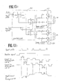
- Fig. 13a is a block diagram of a drive circuit for letting the current flow through the above electromagnetic coils 30, 32, and Fig. 13b shows the relation between the input pulse and the moving unit 40.
- a current pulse having a pulse width T is selectively outputted to the electromagnetic coils 30, 32 from drive circuits 152, 153 which have the function of letting the current flow through the electromagnetic coils 30, 32 in both directions accordingly.
- the moving units 20, 40 respectively perform step motions stepwise in proportion to the input pulse by the distance s while changing the holding position alternately accompanied with the delay time by inertia to the current pulse.
- the changeover of the direction signal they perform the step motion by the distance s in the opposite direction.
- a linear actuator in which, by alternately letting the current flow through a pair of electromagnetic coils which are the magnetic drive means and varying the direction and amount of current flowing, the holding force of each moving unit is selectively controlled to perform the step motions in bi-directions. Accordingly, as it has a construction to house all the drive systems necessary for the step motion in the actuator without necessitating a special rail for the traveling path, it is possible to realize a simple construction having as a whole small number of parts. Moreover, as no high precision is required for the whole traveling path and the suspension is simplified, it is rich in productivity.
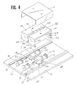
- Fig. 4 shows a second embodiment of the present invention.
- the step linear actuator of this embodiment similarly comprises a stationary baseplate 10 and a pair of moving units 20, 40 which are in contact with said baseplate and are relatively freely displaceable at a prescribed stroke in the direction of advance to each other.
- the moving unit 20 has yokes 21, 24 which are in contact with the stationary baseplate 10 in a positional relationship of crossing at right angles therewith and have contact faces 21a, 24a, and a permanent magnet 25 whose two end faces of different magnetic poles are clamped between the yokes 21, 24 in contact with the stationary baseplate 10 to constitute a magnetic coupling means.
- a magnetic flux path is formed between the stationary baseplate 10 and each of the yokes 21, 24, and the moving unit is magnetically coupled with the stationary baseplate 10.
- the moving unit 40 has one-side opened square shaped yokes 41, 43 having the contact faces 41a, 41b which are in contact with the stationary baseplate 10, and a permanent magnet 42 having the different magnetic poles between said yokes 41, 43 and the two end faces are clamped to constitute a magnetic coupling means.
- a magnetic flux path is formed between the stationary baseplate 10 and each of the yokes 41, 43 and are magnetically coupled with the baseplate 10.
- magnetization is made in the same direction so that the flow of the magnetic fluxes through the magnetic flux paths in the moving units 20, 40 is in the same direction.
- a pair of yokes 22, 23 each having a square section projecting in parallel with the stationary baseplate 10 in bi-directions respectively along the direction of advance and the other pair of yokes 26, 27.
- a pair of the inner faces 41c, 41d of the yoke 41 which are vertically positioned to the stationary baseplate 10 of the yoke 41 are opposed to the yoke end faces 22a, 23a of the moving unit 20 and the inner faces 43c, 43d of the yoke 43 to the yoke end faces 26a, 27a, through a slight gap, constituting the respective opposing faces.
- a pair of electromagnetic coils 30, 32 wound on the coil bobbins 31, 33 and 35, 37 and the other pair of electromagnetic coils 34, 36, respectively.
- the electromagnetic coils 30, 32 utilized respectively as sources of magnetomotive forces, for example, assuming the electro-magnetic coil 30 to be a source of a magnetomotive force, a magnetic flux Path is formed so as to let flow a constant magnetic flux to the yoke 41, contact faces 41a, 41b, stationary baseplate 10, contact face 21a, and yoke 21 through the yoke end face 22a.
- the guide member at the stationary baseplate 10 is the same as in the first embodiment.
- the motion of the step linear actuator constituted as above is basically the same as in the first embodiment. ln case of driving in the direction of advance, firstly in order to have the moving unit 40 held by the stationary baseplate 10 and the other moving unit 20 displaced by a prescribed stroke, current is let flow simultaneously in the respectively different directions through a pair of electromagnetic coils 30, 34 disposed in parallel so as to form N pole on the yoke end face 22a and S pole on the yoke end face 26a.
- this embodiment has a construction to make it easy to overlap the magnetic fluxes of the pair of electromagnetic coils 30, 34 and 32, 36 against the magnetic fluxes by the magnetic coupling means of the stationary baseplate 10 and the moving units 20, 40, it is possible to control selectively and certainly the contact forces of the moving units 20, 40 to the stationary baseplate 10.
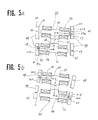
- a rotary motion centering on the permanent magnets 25, 42 as shown in Fig. 5a and Fig. 5b can be performed. As shown in Fig.
- the electromagnetic coils 30, 36 are symmetrically arranged so as to cross at the center of the permanent magnet 25 of the moving unit 20, through which current is let flow so that the magnetic fluxes 56, 57 are led in the direction of solid line in the drawing so that the contact force is decreased at the contact faces 21a, 24a and the contact force is increased at the contact faces 41a, 41b, by which the moving unit 40 is held stationary on the baseplate 10, and the moving unit 20 is rotationally displaced by the clockwise rotary moment by the electromagnetic force which acts between the opposing faces 41c, 22a and the opposing faces 43d, 27a to assume the positional relation of Fig. 5a.
- each of the moving units 20, 40 is displaced while being self-held in an optional direction on the stationary baseplate 10.
- FIG. 6 and Fig. 7 show a third embodiment.
- This embodiment also comprises a pair of moving units 20, 40 which are in contact with the stationary baseplate 10 and are freely relatively displaceable by a prescribed stroke in the direction of advance.
- the moving units 20, 40 are in contact with the stationary baseplate 10 at the contact faces 21a, 41a, and are accompanied with the yokes 21, 41 arranged in parallel with the direction of advance, and the yokes 24, 43 having a certain gap with the stationary baseplate 10 at the respective end faces nearly at the central parts of said yokes 21, 41, and permanent magnets 25, 42 which constitute the magnetic coupling members to form respectively magnetic coupling with the stationary baseplate 10.
- yokes 22, 23 and 46, 47 which respectively project in the direction crossing at right angles to the direction of advance and opposed to one another through a certain gap in both sides respectively to each of the contact faces 21a, 41a, coupled with the yokes 21, 41.
- a plurality of tooth-like magnetic pole teeth 28, 48 having a constant pitch are formed on the opposing faces 22a, 46a and 23a, 47a.
- Either one of the pair of opposing faces 22a, 46a and the other pair of opposing faces 23a, 47a is constituted with 1/4 pitch displacement of the pitch of the magnetic pole teeth 28, 48, and the other opposing faces are opposed at the same pitch.
- the electromagnetic coils 30, 32 which are respectively the magnetic drive means, wound on the coil bobbins 31, 32, are fitted. Magnetic flux paths are formed so that, with the electromagnetic coils 30, 32 as sources of the respective magnetomotive forces, a constant magnetic flux is let through the gap between the opposing faces 22a, 46a, each of the yokes 21, 41 and the stationary baseplate 10, or through the gap between the opposing faces 23a, 47a, each of the yokes 21, 41 and the stationary baseplate 10.
- the motion of the step linear actuator constructed as above is basically similar to that of the first embodiment. ln case of the non-flow of current, the actuator is self-held to the stationary baseplate 10 by means of the magnetic coupling member.
- the electromagnetic coil 30 By letting the current flow through the electromagnetic coil 30 so that the magnetic flux 50 flows in the direction of the solid line as shown in Fig. 7, the magnetic flux 50 is overlapped with the magnetic fluxes 29, 49 formed by the permanent magnets 25, 42 at the contact faces 21a, 41a, by which the moving unit 20 is more held to the stationary baseplate 10, while on the contrary the moving unit 40 becomes freely displaceable.
- the moving unit 40 is relatively displaced from the condition in which the pitches of the magnetic pole teeth are displaced by 1/4 pitch to the mutually opposing positions.
- continuous linear motion can be realized by a slight relative displacement between the magnetic pole teeth of each yoke while the opposing faces are holding a certain gap. Accordingly, there is not necessitated high precision members for the whole traveling path.
- the prescribed stroke can be obtained in high precision. Also, no sound of collision between the yokes occurs. High reliability is obtained in durable life.
- the gap holding member 19 is to keep a certain gap against the electromagnetic force formed between the yoke opposing faces 22a, 46a and between 23a, 47a.
- the guide members 15, 16 provided on the stationary baseplate 10 may be constituted as parts of said gap holding member 19 to provide the same functions as above.
- Fig. 8 shows a fourth embodiment.
- This embodiment similarly comprises a pair of moving units 20, 40 which are in contact with the stationary baseplate 10 and freely relatively displaceable in the direction of advance by a prerscribed stroke.
- the means of always returning the relative positions to the initial positional relation is performed by a spring member instead of the former use of an electromagnetic coil.
- the moving units 20 and 40 have the yokes 21 and 41 with arrangements of the permanent magnets 25, 42 on the sides and accompanied respectively with the contact faces 21a and 41a on the stationary baseplate 10, as described above. They are magnetically coupled on the stationary baseplate 10.
- a yoke 22 opposing to the inner face 41c of the yoke 41 and projecting so as to constitute mutually opposing faces 22a, 41c is coupled to the yoke 21.
- an electromagnetic coil 30 accompanied with a coil bobbin 31 is fitted to the said yoke 22.
- a magnetic flux path is formed so that a constant magnetic flux flows through the yoke 22, yoke 41, stationary baseplate 10 and yoke 21. By said magnetic flux the yokes are subjected to relative displacement.
- a compression coil spring 12 is provided with its force exerted in the direction to separate the opposing faces 22a, 41c from each other.
- a control member 14 which is resin molded in one-piece with the outer side of the yoke 21 and controls the widthwise direction of the yoke 41 along with the control of the displacement of the direction of advance of the moving unit 40, surrounds the yoke 41 and holds it in contact with it.
- the moving unit 40 by letting the current flow through the electromagnetic coil 30, the moving unit 40 is held by the stationary baseplate 10 and the moving unit 20 becomes freely relatively displaceable by a prescribed stroke.
- the moving unit 20 By the electromagnetic force produced between the opposing faces 22a, 41c, the moving unit 20 is displaced stepwise only by an effective gap amount against the compression coil spring 12.
- the moving units 20 and 40 are displaced in a mutually alienating direction to the position of the yoke 41 coming in contact with the control member 14.
- the moving units 20, 40 are relatively displaced while being returned by the coil spring 12 against the mutual displacement by the electromagnetic coil 30.
- the returned displacement amount varies depending on the trailing time of the electromagnetic coil 30, each mass of each moving unit, and the holding force at each of the contact faces 21a, 41a formed by the magnetic force.
- the present embodiment makes it possible to perform bidirectional linear motions by a very simple construction comprising, for example, an electromagnetic coil 30 and a spring member 12.
- Fig. 9 shows a fifth embodiment.
- the stationary member is constructed by an axial member 111 which has a central axis in the direction of advance and is made of a magnetic material, and comprises a pair of moving units 120, 140 which are in contact with said axial member 111 and are freely relatively displaceable by a prescribed stroke to each other in the direction of advance.
- the moving unit 120 has a disk yoke 121 which is coaxially disposed on the axial member 111 and carried in contact with the axial member 111 at the central opening and has a contact face 121a; a yoke 124 having a central opening end face 124a which is coaxially disposed via a certain gap on the axial member 111 similarly adjacent to said yoke 121; and a ring form permanent magnet 125 which is similarly coaxially disposed with the axial member 111 with its two end faces having different magnetic poles clamped by said yokes 121, 124.
- a magnetic flux path is formed so that, with said permanent magnet 125 utilized as a source of a magnetomotive force, a certain magnetic flux is let flow through the yoke 121, contact face 121a, axial member 111, gap between the axial member 111 and the yoke end face 124a, and yoke 124.
- the moving unit 140 has a yoke 141 which is disposed coaxially with the axial member 111 alienated from the yoke 121 and has the similar construction as the moving unit 120, a yoke contact face 141a, a yoke 143 and a permanent magnet 142.
- said permanent magnet 142 utilized as a source of a magnetomotive force, a magnetic flux path is formed between the axial member 111 and the moving unit 140.
- the permanent magnets 125, 142 are magnetized in the same direction so that the directions of magnetization of the magnetic fluxes become constant at the contact faces 121a, 141a.
- Each of the moving units 120, 140 is magnetically coupled to the axial member 111 by means of the magnetic coupling member.
- a cylindrical yoke 122 is disposed coaxially with the axial member 111, and its end face 122a is opposed to the inner side face 141b of the yoke 141 through a slight gap to constitute a pair of opposing faces to the moving units 120, 140.
- an electromagnetic coil 130 which has a central opening and is disposed with a slight gap with the axial member 111 and is accompanied with a coil bobbin 131.
- a magnetic flux path is formed between the yoke 141, axial member 111, contact face 121a and yoke 121 through the gap between the yoke 122a and the side face 141b.
- an electromagnetic force is generated between the opposing faces 122a and 141b to cause relative displacement of the moving units 120 and 140 in the mutually attracting direction on the axial member 111.
- a compression coil 112 is provided coaxially with the axial member 111 so as to exert force to the yokes 121 and 141 in the mutually alienating direction.
- a casing 113 on the cup for controlling the displacement of the moving unit 120 on the axial member 111 and a disk member 114 which is engaged with said casing 113 for controlling the displacement of the yoke 124 of the moving unit 120 in the axial direction are fitted.
- the contact faces 121a, 141a of the yokes 121, 141 are used also as the guide members.
- the moving unit 140 by letting the current flow through the electromagnetic coil 130, the moving unit 140 is held on the stationary baseplate 111 and the moving unit 120 comes to have a condition freely relatively displaceable by the specified stroke, and, by the electromagnetic force produced between the opposing faces 122a and 141b, the moving unit 120 is displaced stepwise only by an effective gap amount against the compression coil spring 112.
- the moving units 120 and 140 are displaced in the mutually alienating direction to the position in which the yoke 124 is in contact with the disk member 114, by which the moving units 120, 140 are mutually relatively displaced.
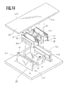
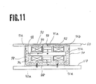
- Fig. 10 and Fig. 11 show a sixth embodiment, which has basically the same construction as the first embodiment.
- Either one of a pair of moving units 20, 40 which are freely slidably supported by the stationary baseplate in the first embodiment is fixed to the apparatus body to which a linear actuator is fitted, and the other moving unit and the above stationary baseplate 10 are made relatively displaceable in the prescribed stroke.
- a stationary member 70 which is similar in structure to the moving unit in Fig. 1 is fixed at the lower face of the central part of the yoke 71.
- the movable baseplate 60 comprising a magnetic material is freely relatively displaceably carried.
- a moving unit 90 which has the similar construction as that of the moving unit 20 of Fig. 1 and has a yoke 91 is disposed in contact with the movable plate 60 at its contact faces 91a, 91b.
- the permanent magnets 72, 95 which are the magnetic coupling members are magnetically coupled to the movable plate 60 at the contact faces 71a, 71b and at the contact faces 91a, 91b, and they are held under magnetization so that the flow of the magnetic fluxes at that time comes to be in the same direction.
- the yokes 92, 93 projecting in parallel to the baseplate 110 from the yoke 91 respectively in bi-directions so as to constitute the opposing faces.
- the electromagnetic coils 80, 82 wound on the coil bobbins 81, 83 are fitted.
- a magnetic flux path is formed so that a constant magnetic flux flows through the yoke 92, opposing face 92a and the inner face 71c of the yoke, contact faces 71a, 71b, movable plate 60, contact faces 91a, 91b and yoke 91 to constitute a magnetic drive means together with the electromagnetic coils 80, 82.
- the guide members 74, 75 are provided integrally therewith to guide the two sides 60a, 60b of the movable plate 60, by which the movable plate 60 is freely movably displaced by a prescribed stroke along the direction of advance.
- the basic motion is similar to that of the first embodiment.
- the movable plate 60 is self-held to the stationary member 70 by means of the magnetic coupling member, and the moving unit 90 is self-held to the said movable plate 60.
- the magnetic flux 88 overlaps the magnetic fluxes 78, 98 by the magnetic coupling member, by which the contact force decreases at the contact faces 71a, 71b of the stationary member 70 and the contact force increases at the contact face 91a of the moving unit 90.
- the movable plate 60 By the electromagnetic force produced between the opposing faces 71c and 91a, the movable plate 60, while being held by the moving unit 90, is displaced together with the movomg unit 90 in the direction of decreasing the gap between the opposing faces 71c and 92a of the stationary member 70.
- the contact force increases at the contact faces 71a, 71b of the stationary member 70 and the contact force decreases at the contact faces 91a, 91b, and, by the electromagnetic force produced between the opposing faces 71d and 93a, with the movable unit 60 being in the condition of being held by the stationary member 70, only the moving unit 90 returns to the initial relative positional relation as shown in Fig. 10 to complete the motions of one cycle.
- the movable plate 60 is allowed to perform step motion continuously. Further, by changing the direction of the current flow through the electromagnetic coils 80, 82, the movable plate 60 can be driven in the opposite direction.
- the above electromagnetic coils 80, 82 have the similar functions even when disposed on the stationary member 70 side.
- step motion can be performed if the movable plate 60 comprises a baseplate made of a magnetic material or made by integrally forming the magnetic material, so that it is possible to realize a linear actuator of a simple construction having the small number of parts. Moreover, it is easy to use the above movable plate also as the member of the apparatus body to which the linear actuator is fitted, so that the simplification as the whole apparatus can also be attained.
- the magnetic drive means is fixed to the side of the stationary member 70 or the moving unit 90, there is no shift accompanied with wiring, because of which it is possible to elevate the reliability of the apparatus, and, due to the small portions of which precision is required against the necessary stroke, the present embodiment has superiority in the property of assembling.
- any member comprising a magnetic material and having linearity for example, of axial shape having a center axis in the direction of advance, may perform the similar function.
- replacement of the permanent magnet of the magnetic coupling member by excitation by an electromagnetic coil may also be effective for performing the similar function.
- the shapes of the members shown in the present embodiments e.g., stationary member, moving units and guide members, are not to be limited.
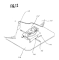
- Fig. 12 shows an example of application of the present invention which is used for an optical pickup traverse system of an optical disk drive for reading out and reproducing, with an optical pickup 102 using a semiconductor laser ray, recorded information from a disk recording medium 101 having an information track recorded spirally or concentrically, in which the step linear actuator 100 is carried in contact with the stationary baseplate 110 which is a base of the disk drive, and the optical pickup 102 is carried on the actuator 100.
- the recording medium 101 is driven in rotation by a spindle motor 103.
- a groove 105 is provided along the radial direction of the recording medium.
- a guide pin 106 for guiding, protruding from the lower part of the linear actuator 100, is disposed 1n freely fitting condition on said groove 105.
- the linear actuator 100 is driven, guided by the groove 105, while correcting the track error of the optical pickup 102 against the recording medium 101 in the radial direction of the recording medium 101.
Landscapes
- Physics & Mathematics (AREA)
- Electromagnetism (AREA)
- Engineering & Computer Science (AREA)
- Power Engineering (AREA)
- Reciprocating, Oscillating Or Vibrating Motors (AREA)
- Linear Motors (AREA)
Applications Claiming Priority (6)
| Application Number | Priority Date | Filing Date | Title |
|---|---|---|---|
| JP189011/88 | 1988-07-28 | ||
| JP18901188 | 1988-07-28 | ||
| JP69602/89 | 1989-03-22 | ||
| JP69601/89 | 1989-03-22 | ||
| JP6960289 | 1989-03-22 | ||
| JP6960189 | 1989-03-22 |
Publications (3)
| Publication Number | Publication Date |
|---|---|
| EP0353074A2 true EP0353074A2 (de) | 1990-01-31 |
| EP0353074A3 EP0353074A3 (de) | 1991-10-09 |
| EP0353074B1 EP0353074B1 (de) | 1995-09-13 |
Family
ID=27300089
Family Applications (1)
| Application Number | Title | Priority Date | Filing Date |
|---|---|---|---|
| EP89307662A Expired - Lifetime EP0353074B1 (de) | 1988-07-28 | 1989-07-28 | Linearantrieb |
Country Status (4)
| Country | Link |
|---|---|
| US (1) | US5091710A (de) |
| EP (1) | EP0353074B1 (de) |
| KR (1) | KR930007591B1 (de) |
| DE (1) | DE68924217T2 (de) |
Cited By (2)
| Publication number | Priority date | Publication date | Assignee | Title |
|---|---|---|---|---|
| GB2324910A (en) * | 1997-05-02 | 1998-11-04 | Robert Graham Harris | A linear actuator |
| WO2014108190A1 (de) * | 2013-01-10 | 2014-07-17 | Hochschule für Gestaltung Schwäbisch-Gmünd | Aktuator und verwendung eines aktuators |
Families Citing this family (5)
| Publication number | Priority date | Publication date | Assignee | Title |
|---|---|---|---|---|
| US6229675B1 (en) * | 1993-01-20 | 2001-05-08 | Nippon Petrochemicals Co., Ltd | Swing arm actuator for magnetic disk unit |
| US6140899A (en) * | 1997-10-10 | 2000-10-31 | Display Edge Technology Ltd. | Magnetic coupler and associated method for coupling conductors |
| US6005462A (en) * | 1998-02-24 | 1999-12-21 | Myers; John Leonard | Electromagnetic core-energy actuator |
| FR2781938B1 (fr) * | 1998-07-30 | 2003-09-19 | Hutchinson | Moteur electromagnetique et dispositif de controle actif des vibrations comportant au moins un tel moteur |
| AU2002315180A1 (en) * | 2001-06-12 | 2002-12-23 | Pelikan Technologies, Inc. | Electric lancet actuator |
Family Cites Families (8)
| Publication number | Priority date | Publication date | Assignee | Title |
|---|---|---|---|---|
| DE1265302B (de) * | 1963-03-02 | 1968-04-04 | Albert Stecker Dipl Ing | Elektromagnetischer Schrittantrieb fuer sehr kleine definierte Schrittbewegungen |
| NL7302941A (de) * | 1973-03-02 | 1974-09-04 | ||
| JPS5967881A (ja) * | 1982-10-06 | 1984-04-17 | Matsushita Electric Ind Co Ltd | 電磁機械変換装置 |
| US4797645A (en) * | 1984-03-05 | 1989-01-10 | Mitsubishi Mining & Cement Co., Ltd. | Electromagnetic actuator |
| US4717900A (en) * | 1984-03-30 | 1988-01-05 | Aisin Seiki Kabushiki Kaisha | Low profile electromagnetic linear motion device |
| FR2568056B1 (fr) * | 1984-07-20 | 1987-01-23 | Telemecanique Electrique | Electroaimant polarise a trois etats et circuit pour sa commande |
| JPS6379304A (ja) * | 1986-06-02 | 1988-04-09 | Fuji Electric Co Ltd | 有極電磁石装置 |
| US4697164A (en) * | 1986-08-18 | 1987-09-29 | Eilertsen John L | Incrementally indexing linear actuator |
-
1989
- 1989-07-25 US US07/384,764 patent/US5091710A/en not_active Expired - Fee Related
- 1989-07-28 KR KR1019890010718A patent/KR930007591B1/ko not_active Expired - Fee Related
- 1989-07-28 EP EP89307662A patent/EP0353074B1/de not_active Expired - Lifetime
- 1989-07-28 DE DE68924217T patent/DE68924217T2/de not_active Expired - Fee Related
Cited By (3)
| Publication number | Priority date | Publication date | Assignee | Title |
|---|---|---|---|---|
| GB2324910A (en) * | 1997-05-02 | 1998-11-04 | Robert Graham Harris | A linear actuator |
| GB2324910B (en) * | 1997-05-02 | 2001-01-03 | Robert Graham Harris | A linear actuator |
| WO2014108190A1 (de) * | 2013-01-10 | 2014-07-17 | Hochschule für Gestaltung Schwäbisch-Gmünd | Aktuator und verwendung eines aktuators |
Also Published As
| Publication number | Publication date |
|---|---|
| KR910003904A (ko) | 1991-02-28 |
| DE68924217D1 (de) | 1995-10-19 |
| US5091710A (en) | 1992-02-25 |
| EP0353074A3 (de) | 1991-10-09 |
| DE68924217T2 (de) | 1996-05-09 |
| EP0353074B1 (de) | 1995-09-13 |
| KR930007591B1 (ko) | 1993-08-13 |
Similar Documents
| Publication | Publication Date | Title |
|---|---|---|
| EP1158547B1 (de) | Elektromagnetischer Aktuator | |
| US5245232A (en) | Linear actuator | |
| US4905031A (en) | Axial magnetic actuator | |
| EP0353074B1 (de) | Linearantrieb | |
| US4578622A (en) | Linear pulse motor | |
| JPS6318431B2 (de) | ||
| JPS5849099B2 (ja) | 可動コイル型リニアモ−タ | |
| US4847726A (en) | Magnetic actuator | |
| JP2682156B2 (ja) | 歩進型リニアアクチュエータ | |
| JP4522674B2 (ja) | 小型スライド装置 | |
| JPS626863Y2 (de) | ||
| JPS59156149A (ja) | リニヤモ−タ | |
| JPS6347070B2 (de) | ||
| JPS6314584B2 (de) | ||
| JP2825323B2 (ja) | ボイスコイル型リニアモータ | |
| JPH0312058Y2 (de) | ||
| JPH09261942A (ja) | リニアパルスモータ | |
| JPS614455A (ja) | リニアモ−タ | |
| JPH0564413A (ja) | リニアアクチユエータ | |
| JPH0550225B2 (de) | ||
| JPS5989565A (ja) | リニアパルスモ−タ | |
| JPS62114464A (ja) | リニアパルスモ−タ | |
| JPS6316884B2 (de) | ||
| JPS59156150A (ja) | リニヤモ−タ | |
| JPS619159A (ja) | リニアモ−タ |
Legal Events
| Date | Code | Title | Description |
|---|---|---|---|
| PUAI | Public reference made under article 153(3) epc to a published international application that has entered the european phase |
Free format text: ORIGINAL CODE: 0009012 |
|
| AK | Designated contracting states |
Kind code of ref document: A2 Designated state(s): DE FR GB NL |
|
| PUAL | Search report despatched |
Free format text: ORIGINAL CODE: 0009013 |
|
| AK | Designated contracting states |
Kind code of ref document: A3 Designated state(s): DE FR GB NL |
|
| 17P | Request for examination filed |
Effective date: 19920331 |
|
| 17Q | First examination report despatched |
Effective date: 19930602 |
|
| GRAA | (expected) grant |
Free format text: ORIGINAL CODE: 0009210 |
|
| AK | Designated contracting states |
Kind code of ref document: B1 Designated state(s): DE FR GB NL |
|
| REF | Corresponds to: |
Ref document number: 68924217 Country of ref document: DE Date of ref document: 19951019 |
|
| ET | Fr: translation filed | ||
| PLBE | No opposition filed within time limit |
Free format text: ORIGINAL CODE: 0009261 |
|
| STAA | Information on the status of an ep patent application or granted ep patent |
Free format text: STATUS: NO OPPOSITION FILED WITHIN TIME LIMIT |
|
| 26N | No opposition filed | ||
| PGFP | Annual fee paid to national office [announced via postgrant information from national office to epo] |
Ref country code: FR Payment date: 19970709 Year of fee payment: 9 |
|
| PGFP | Annual fee paid to national office [announced via postgrant information from national office to epo] |
Ref country code: GB Payment date: 19970721 Year of fee payment: 9 |
|
| PGFP | Annual fee paid to national office [announced via postgrant information from national office to epo] |
Ref country code: NL Payment date: 19970731 Year of fee payment: 9 |
|
| PGFP | Annual fee paid to national office [announced via postgrant information from national office to epo] |
Ref country code: DE Payment date: 19970801 Year of fee payment: 9 |
|
| PG25 | Lapsed in a contracting state [announced via postgrant information from national office to epo] |
Ref country code: GB Free format text: LAPSE BECAUSE OF NON-PAYMENT OF DUE FEES Effective date: 19980728 |
|
| PG25 | Lapsed in a contracting state [announced via postgrant information from national office to epo] |
Ref country code: NL Free format text: LAPSE BECAUSE OF NON-PAYMENT OF DUE FEES Effective date: 19990201 |
|
| GBPC | Gb: european patent ceased through non-payment of renewal fee |
Effective date: 19980728 |
|
| PG25 | Lapsed in a contracting state [announced via postgrant information from national office to epo] |
Ref country code: FR Free format text: LAPSE BECAUSE OF NON-PAYMENT OF DUE FEES Effective date: 19990331 |
|
| NLV4 | Nl: lapsed or anulled due to non-payment of the annual fee |
Effective date: 19990201 |
|
| PG25 | Lapsed in a contracting state [announced via postgrant information from national office to epo] |
Ref country code: DE Free format text: LAPSE BECAUSE OF NON-PAYMENT OF DUE FEES Effective date: 19990501 |
|
| REG | Reference to a national code |
Ref country code: FR Ref legal event code: ST |