EP0353152A1 - Vorrichtung zum Abführen von Erdreich für die Herstellung von Tiefgräben - Google Patents
Vorrichtung zum Abführen von Erdreich für die Herstellung von Tiefgräben Download PDFInfo
- Publication number
- EP0353152A1 EP0353152A1 EP89402126A EP89402126A EP0353152A1 EP 0353152 A1 EP0353152 A1 EP 0353152A1 EP 89402126 A EP89402126 A EP 89402126A EP 89402126 A EP89402126 A EP 89402126A EP 0353152 A1 EP0353152 A1 EP 0353152A1
- Authority
- EP
- European Patent Office
- Prior art keywords
- section
- telescopic tube
- pulley
- tube
- cuttings
- Prior art date
- Legal status (The legal status is an assumption and is not a legal conclusion. Google has not performed a legal analysis and makes no representation as to the accuracy of the status listed.)
- Granted
Links
- 238000005520 cutting process Methods 0.000 claims abstract description 15
- 238000005553 drilling Methods 0.000 claims abstract description 11
- 238000009412 basement excavation Methods 0.000 claims abstract description 10
- 238000003801 milling Methods 0.000 claims description 11
- 239000011521 glass Substances 0.000 claims description 3
- 241000220223 Fragaria Species 0.000 description 3
- 235000021012 strawberries Nutrition 0.000 description 3
- 230000000903 blocking effect Effects 0.000 description 2
- 238000000926 separation method Methods 0.000 description 2
- 241001415961 Gaviidae Species 0.000 description 1
- 238000006073 displacement reaction Methods 0.000 description 1
- 239000000203 mixture Substances 0.000 description 1
- 230000004048 modification Effects 0.000 description 1
- 238000012986 modification Methods 0.000 description 1
- 238000005086 pumping Methods 0.000 description 1
- 238000011084 recovery Methods 0.000 description 1
Images



Classifications
-
- E—FIXED CONSTRUCTIONS
- E21—EARTH OR ROCK DRILLING; MINING
- E21B—EARTH OR ROCK DRILLING; OBTAINING OIL, GAS, WATER, SOLUBLE OR MELTABLE MATERIALS OR A SLURRY OF MINERALS FROM WELLS
- E21B17/00—Drilling rods or pipes; Flexible drill strings; Kellies; Drill collars; Sucker rods; Cables; Casings; Tubings
- E21B17/02—Couplings; joints
- E21B17/04—Couplings; joints between rod or the like and bit or between rod and rod or the like
- E21B17/07—Telescoping joints for varying drill string lengths; Shock absorbers
-
- E—FIXED CONSTRUCTIONS
- E21—EARTH OR ROCK DRILLING; MINING
- E21B—EARTH OR ROCK DRILLING; OBTAINING OIL, GAS, WATER, SOLUBLE OR MELTABLE MATERIALS OR A SLURRY OF MINERALS FROM WELLS
- E21B17/00—Drilling rods or pipes; Flexible drill strings; Kellies; Drill collars; Sucker rods; Cables; Casings; Tubings
- E21B17/20—Flexible or articulated drilling pipes, e.g. flexible or articulated rods, pipes or cables
-
- E—FIXED CONSTRUCTIONS
- E21—EARTH OR ROCK DRILLING; MINING
- E21B—EARTH OR ROCK DRILLING; OBTAINING OIL, GAS, WATER, SOLUBLE OR MELTABLE MATERIALS OR A SLURRY OF MINERALS FROM WELLS
- E21B19/00—Handling rods, casings, tubes or the like outside the borehole, e.g. in the derrick; Apparatus for feeding the rods or cables
- E21B19/22—Handling reeled pipe or rod units, e.g. flexible drilling pipes
-
- E—FIXED CONSTRUCTIONS
- E21—EARTH OR ROCK DRILLING; MINING
- E21B—EARTH OR ROCK DRILLING; OBTAINING OIL, GAS, WATER, SOLUBLE OR MELTABLE MATERIALS OR A SLURRY OF MINERALS FROM WELLS
- E21B21/00—Methods or apparatus for flushing boreholes, e.g. by use of exhaust air from motor
- E21B21/01—Arrangements for handling drilling fluids or cuttings outside the borehole, e.g. mud boxes
-
- E—FIXED CONSTRUCTIONS
- E21—EARTH OR ROCK DRILLING; MINING
- E21B—EARTH OR ROCK DRILLING; OBTAINING OIL, GAS, WATER, SOLUBLE OR MELTABLE MATERIALS OR A SLURRY OF MINERALS FROM WELLS
- E21B7/00—Special methods or apparatus for drilling
- E21B7/003—Drilling with mechanical conveying means
Definitions
- the present invention relates to a device for removing cuttings when making trenches or excavation of great depth.
- a solution consists in interrupting the drilling to lengthen by adding a new element the pipe which is used for the evacuation of the cuttings.
- This solution has the drawback of requiring work to be interrupted, which constitutes a significant loss of time and money, given the immobilization of very expensive equipment which is necessary for this type of work.
- the present invention relates to a device which makes it possible to dig trenches or excavations of great depth using a lifting device whose height is only a fraction of the depth of the trench and without it it is necessary to interrupt drilling to modify the structure of the device which allows the removal of cuttings.
- the subject of the present invention is a device for the evacuation of cuttings resulting from the drilling of a trench or an excavation under mud at a great depth, characterized by the fact that the cuttings evacuation pipe comprises a first lower section arranged in the vicinity of the drilling cutters, which is constituted by a telescopic tube and a second section constituted by a flexible tube connected to the first section by one of its ends and the other end of which terminates in the vicinity of the ground at the point of unloading the spoil , this second section being supported between its two ends by a pulley which is suspended from the upper part of the lifting machine, and the height of which can be modified during work.
- a blocking device which allows the two elements of the telescopic tube to be joined, in particular in the position where these two elements are inserted into one another.
- the second flexible section of pipe is supported by a pulley itself suspended from a cable descending from the top of the lifting device which is wound on a winch preferably exerting a constant force .
- the flexible section of the pipeline automatically adapts to the configuration of the device which varies with the descent of the cutters into the ground.
- the upper part of the female element of the telescopic tube as well as the upper part of the male element of this tube are held in vertical position by means of guide glasses of which they are integral and which are crossed by a cable which supports the milling machine during its work.
- the device according to the invention makes it possible for example, using a lifting device which has a total height of approximately 50 meters, to dig excavations the depth of which can reach approximately 140 meters without it being necessary to modify the structure of the device when lowering the cutter into the trench.
- the device according to the invention can be implemented in different ways.
- the two elements of the telescopic tube are tucked into each other and are locked on each other so that the telescopic tube does not stretch under the action of the discharge pressure of the cuttings, while the pulley supporting the flexible section is raised to the top of the lifting machine.
- the pulley is then gradually lowered as the drilling progresses so that the telescopic tube, the two elements of which are tucked into each other, sinks into the ground as the cutter descends and this until the top of the telescopic tube reaches ground level.
- the cutter can continue to descend, while the two telescopic tube elements gradually move away from each other until their maximum.
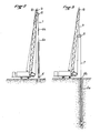
- milling machine 4 which is intended to dig in the ground the trench 5 while being suspended at the top of the crane by one or more cables not shown.
- the cutters are driven in rotation using electric or hydraulic motors which are supplied from the crane or from a power unit by pipes not shown.
- the evacuation of drill cuttings mixed with the mud of the trench is carried out according to the invention by a pipe which comprises a first telescopic section 6 constituted by a female element 6 a inside which can slide a male element 6 b which itself constitutes a tube allowing the circulation of cuttings and mud.
- a blocking device not shown makes it possible to immobilize the element 6b with respect to element 6 a , in particular in the position where these two elements are completely tucked into each other, as seen in FIG. 1.
- the flexible pipe section 7 is supported by a pulley 8 itself suspended from a cable 9 passing over a pulley 10 at the top of the mast 3 of the crane, so that from the ground, it is possible to move the pulley 8 as desired to raise or lower it relative to the top of the crane.
- the other end of the cable 9 is connected to a winch which exerts on it a constant force which thus makes it possible automatically to adapt the position of the pulley 8 to the descent of the cutter .
- the device according to the invention is shown in FIG. 1 in its highest position, the male element 6 b being retracted as far as possible in the female element 6 a of the telescopic section 6, and the pulley 8 being raised in its highest position in relation to the top of the crane.
- the strawberries are located slightly above the ground.
- the extent of the descent of the cutter 4 corresponds substantially to twice the height of the lifting machine plus the increase in length of the telescopic section 6 which corresponds to the maximum output of the element 6 b out of element 6 a .
- FIGS. 2 to 5 show the different phases of using the device according to the invention.
- FIG. 2 shows the device in its initial position for which the male element 6 b of the telescopic tube is completely retracted into the female element 6 a , the pulley 8 being brought back to the top of the lifting machine.
- the cutters are located substantially at ground level, and the elements 6 a and 6 b are secured to each other by any device placed at the top of the telescopic tube.
- the cable 9 which supports the pulley 8 is connected to a winch with constant torque so that the pulley 8 is subjected to a sufficient upward force to maintain the flexible section 7 of the pipeline while being able to follow the downward movement of strawberries which gradually sink into the ground by digging the trench.
- the male 6 b engages by first stationary element in the trench followed by the lower end of the flexible tube section 7.
- This device is useful first of all for guiding the male element 6 b when it is lifted from the female element 6 a and on the other hand also for holding the upper part of the female element 6 a in the event where the telescopic tube protrudes substantially above the chassis of the milling machine as is the case in the embodiment shown in Figure 1.
- FIG. 6 shows the female element 6 a of the female telescopic tube 6 a in which the male element 6 b slides.
- the upper part of the male element 6 b is connected to the end of the flexible pipe 7.
- the telescopic tube can rise over a height of several tens of meters above the frame of the milling machine.
- the flexible tube 7 is liable to be subjected to movements due to the pumping of the cuttings, it is understood that it is preferable to keep the upper part of the telescopic tube in alignment with its lower part.
- this type of device comprises milling machines of considerable weight and which it is necessary to support using one or more cables which terminate at the top of the lifting machine and which by the traction exerted on them makes it possible to determine the bearing force on the ground of the milling machine.
- this or these support cables are perfectly vertical and aligned with the milling machine.
- a second arm 16 is fixed with a screw socket 17 on the upper part of the male element 6 b and is provided with a bezel 18 at the inside of which the cable passes 12.
Landscapes
- Engineering & Computer Science (AREA)
- Life Sciences & Earth Sciences (AREA)
- Geology (AREA)
- Mining & Mineral Resources (AREA)
- Mechanical Engineering (AREA)
- Physics & Mathematics (AREA)
- Environmental & Geological Engineering (AREA)
- Fluid Mechanics (AREA)
- General Life Sciences & Earth Sciences (AREA)
- Geochemistry & Mineralogy (AREA)
- Earth Drilling (AREA)
Priority Applications (1)
| Application Number | Priority Date | Filing Date | Title |
|---|---|---|---|
| AT89402126T ATE77428T1 (de) | 1988-07-26 | 1989-07-26 | Vorrichtung zum abfuehren von erdreich fuer die herstellung von tiefgraeben. |
Applications Claiming Priority (2)
| Application Number | Priority Date | Filing Date | Title |
|---|---|---|---|
| FR8810067A FR2634805B1 (fr) | 1988-07-26 | 1988-07-26 | Dispositif d'evacuation des deblais pour la realisation de tranchees de grande profondeur |
| FR8810067 | 1988-07-26 |
Publications (2)
| Publication Number | Publication Date |
|---|---|
| EP0353152A1 true EP0353152A1 (de) | 1990-01-31 |
| EP0353152B1 EP0353152B1 (de) | 1992-06-17 |
Family
ID=9368784
Family Applications (1)
| Application Number | Title | Priority Date | Filing Date |
|---|---|---|---|
| EP89402126A Expired - Lifetime EP0353152B1 (de) | 1988-07-26 | 1989-07-26 | Vorrichtung zum Abführen von Erdreich für die Herstellung von Tiefgräben |
Country Status (13)
| Country | Link |
|---|---|
| US (1) | US4971157A (de) |
| EP (1) | EP0353152B1 (de) |
| JP (1) | JPH0739672B2 (de) |
| AR (1) | AR240708A1 (de) |
| AT (1) | ATE77428T1 (de) |
| CA (1) | CA1317604C (de) |
| CY (1) | CY1717A (de) |
| DE (2) | DE68901826T2 (de) |
| ES (1) | ES2014203T3 (de) |
| FR (1) | FR2634805B1 (de) |
| HK (1) | HK88693A (de) |
| RU (1) | RU1838519C (de) |
| SG (1) | SG46493G (de) |
Cited By (1)
| Publication number | Priority date | Publication date | Assignee | Title |
|---|---|---|---|---|
| US10995563B2 (en) | 2017-01-18 | 2021-05-04 | Minex Crc Ltd | Rotary drill head for coiled tubing drilling apparatus |
Families Citing this family (6)
| Publication number | Priority date | Publication date | Assignee | Title |
|---|---|---|---|---|
| US5249379A (en) * | 1992-09-15 | 1993-10-05 | Eagle-Picher Industries, Inc. | Mounting structure for the linear actuators of a trenching apparatus |
| FR2856088B1 (fr) * | 2003-06-11 | 2005-09-09 | Cie Du Sol | Outil de fraisage pour la realisation de tranchees, permettant un changement rapide de la tete de coupe |
| WO2009026449A1 (en) * | 2007-08-21 | 2009-02-26 | Bay Shore Systems Inc. | Excavation apparatuses and methods |
| US20110061313A1 (en) * | 2009-09-16 | 2011-03-17 | Vos Donald | Adapters for the boom arm of an aerial work platform |
| BR112016000967A2 (pt) | 2013-07-17 | 2017-08-29 | Bp Exploration Operating Co Ltd | Método de recuperação de óleo |
| CN110952926B (zh) * | 2020-01-17 | 2020-10-09 | 东阳市菊苏科技有限公司 | 一种家用钻进装置 |
Citations (5)
| Publication number | Priority date | Publication date | Assignee | Title |
|---|---|---|---|---|
| US2548616A (en) * | 1948-02-02 | 1951-04-10 | Priestman George Dawson | Well drilling |
| US3285629A (en) * | 1963-12-11 | 1966-11-15 | Roy H Cullen | Methods and apparatus for mounting electrical cable in flexible drilling hose |
| US3313346A (en) * | 1964-12-24 | 1967-04-11 | Chevron Res | Continuous tubing well working system |
| US3599735A (en) * | 1970-01-22 | 1971-08-17 | Bowen Tools Inc | Bumper sub and closed fluid circulation assembly |
| US4196781A (en) * | 1978-08-09 | 1980-04-08 | Cheek Alton E | Telescoping joint |
Family Cites Families (7)
| Publication number | Priority date | Publication date | Assignee | Title |
|---|---|---|---|---|
| US2007666A (en) * | 1933-10-14 | 1935-07-09 | Caisson Contracting Company | Water-tight telescopic kelly |
| US2800301A (en) * | 1954-03-18 | 1957-07-23 | Borg Warner | Earth boring apparatus |
| US3255612A (en) * | 1964-02-13 | 1966-06-14 | Gardner Denver Co | Telescoping drilling device |
| CH545891A (de) * | 1971-03-18 | 1974-02-15 | ||
| DE2256054C2 (de) * | 1971-12-31 | 1984-08-16 | Takenaka Komuten Co. Ltd., Osaka | Abraum-Saugbaggereinrichtung mit wenigstens einem Saugschlauch zum Abführen des Abraumschlammes |
| JPS6011952B2 (ja) * | 1977-08-11 | 1985-03-29 | 石川島播磨重工業株式会社 | コ−クス及び他の原料の乾式冷却設備 |
| JPS607095A (ja) * | 1983-06-23 | 1985-01-14 | 松下電器産業株式会社 | 遠赤外線ヒ−タ |
-
1988
- 1988-07-26 FR FR8810067A patent/FR2634805B1/fr not_active Expired - Lifetime
- 1988-10-06 JP JP63252859A patent/JPH0739672B2/ja not_active Expired - Fee Related
-
1989
- 1989-07-25 CA CA000606573A patent/CA1317604C/fr not_active Expired - Fee Related
- 1989-07-25 AR AR31449289A patent/AR240708A1/es active
- 1989-07-25 US US07/384,976 patent/US4971157A/en not_active Expired - Lifetime
- 1989-07-25 RU SU894614692A patent/RU1838519C/ru active
- 1989-07-26 DE DE8989402126T patent/DE68901826T2/de not_active Expired - Fee Related
- 1989-07-26 EP EP89402126A patent/EP0353152B1/de not_active Expired - Lifetime
- 1989-07-26 ES ES198989402126T patent/ES2014203T3/es not_active Expired - Lifetime
- 1989-07-26 AT AT89402126T patent/ATE77428T1/de not_active IP Right Cessation
- 1989-07-26 DE DE198989402126T patent/DE353152T1/de active Pending
-
1993
- 1993-04-15 SG SG46493A patent/SG46493G/en unknown
- 1993-08-26 HK HK886/93A patent/HK88693A/xx unknown
-
1994
- 1994-05-06 CY CY171794A patent/CY1717A/xx unknown
Patent Citations (5)
| Publication number | Priority date | Publication date | Assignee | Title |
|---|---|---|---|---|
| US2548616A (en) * | 1948-02-02 | 1951-04-10 | Priestman George Dawson | Well drilling |
| US3285629A (en) * | 1963-12-11 | 1966-11-15 | Roy H Cullen | Methods and apparatus for mounting electrical cable in flexible drilling hose |
| US3313346A (en) * | 1964-12-24 | 1967-04-11 | Chevron Res | Continuous tubing well working system |
| US3599735A (en) * | 1970-01-22 | 1971-08-17 | Bowen Tools Inc | Bumper sub and closed fluid circulation assembly |
| US4196781A (en) * | 1978-08-09 | 1980-04-08 | Cheek Alton E | Telescoping joint |
Non-Patent Citations (1)
| Title |
|---|
| WORLD OIL, vol. 173, no. 6, novembre 1971, pages 75-77, Houston, US; J.R. THIERY et al.: "Depth record set by rig using flexible drillstem" * |
Cited By (2)
| Publication number | Priority date | Publication date | Assignee | Title |
|---|---|---|---|---|
| US10995563B2 (en) | 2017-01-18 | 2021-05-04 | Minex Crc Ltd | Rotary drill head for coiled tubing drilling apparatus |
| US11136837B2 (en) | 2017-01-18 | 2021-10-05 | Minex Crc Ltd | Mobile coiled tubing drilling apparatus |
Also Published As
| Publication number | Publication date |
|---|---|
| JPH0739672B2 (ja) | 1995-05-01 |
| DE353152T1 (de) | 1990-08-16 |
| US4971157A (en) | 1990-11-20 |
| CY1717A (en) | 1994-05-06 |
| ES2014203T3 (es) | 1993-03-16 |
| HK88693A (en) | 1993-09-03 |
| ATE77428T1 (de) | 1992-07-15 |
| RU1838519C (ru) | 1993-08-30 |
| ES2014203A4 (es) | 1990-07-01 |
| FR2634805B1 (fr) | 1992-04-10 |
| FR2634805A1 (fr) | 1990-02-02 |
| DE68901826D1 (de) | 1992-07-23 |
| JPH0243420A (ja) | 1990-02-14 |
| SG46493G (en) | 1993-07-09 |
| CA1317604C (fr) | 1993-05-11 |
| EP0353152B1 (de) | 1992-06-17 |
| DE68901826T2 (de) | 1993-02-04 |
| AR240708A1 (es) | 1990-09-28 |
Similar Documents
| Publication | Publication Date | Title |
|---|---|---|
| EP0265344B1 (de) | Verfahren zum Herstellen eines Pfahls im Boden, sowie Bohrmaschine und Vorrichtung zur Ausführung dieses Verfahrens | |
| CA1238849A (fr) | Methode et dispositif permettant d'effectuer des mesures et/ou interventions dans un puits | |
| EP0811724B1 (de) | Vorrichtung mit teleskopischem Rahmen zum Graben von Tiefgräben im Boden | |
| FR2841293A1 (fr) | Conduite de guidage telescopique de forage en mer | |
| EP0353152B1 (de) | Vorrichtung zum Abführen von Erdreich für die Herstellung von Tiefgräben | |
| KR20140029276A (ko) | 절단 장치 가이드용 가이드 프레임 | |
| FR2899608A1 (fr) | Outillage de forage | |
| WO2013057442A1 (fr) | Dispositif de forage de grand diametre | |
| FR2584435A1 (fr) | Engin de terrassement destine notamment aux fouilles d'intervention de petites dimensions. | |
| FR2752857A1 (fr) | Appareil pour creuser dans le sol des tranchees de grande profondeur | |
| FR2873155A1 (fr) | Foreuse hydraulique pour travaux en espace reduit | |
| EP0592326B1 (de) | Baggergerät zum Graben von Tiefgräben mit Frästrommeln | |
| EP0114146B1 (de) | Universalbohrgerät versehen mit Mitteln zum schnellen Ziehen des Bohrstranges | |
| EP0253726A1 (de) | Vorrichtung zum Ausheben von Gräben mit Fräsern | |
| FR2565290A1 (fr) | Procede et dispositif de creusement de puits | |
| WO2003040515A1 (fr) | Dispositif de guidage dans une installation de forage en mer et procede de realisation | |
| CA1273965A (fr) | Procede et dispositif de creusement de puits | |
| FR2633602A1 (fr) | Dispositif a grue telescopique, notamment pour le levage et la mise en place de poteaux telegraphiques ou analogues | |
| FR2564894A2 (fr) | Methode et dispositif permettant d'effectuer des mesures et/ou interventions dans un puits. | |
| EP2077355B1 (de) | Digging machine capable of being transported in containers | |
| FR2513693A1 (fr) | Machine de forage polyvalente dotee de moyens de remontee rapide du train de tiges | |
| EP1929094A1 (de) | Maschine zur herstellung einer durchgehenden wand im boden | |
| FR2888259A1 (fr) | Installation et procede de decoupage de structures sous-marines enfoncees dans le fond de la mer | |
| FR2573472A2 (fr) | Methode et dispositif permettant d'effectuer des mesures et/ou interventions dans un puits | |
| EP0592329A1 (de) | Teleskopische Führungvorrichtung für ein Baggergerät zum Graben von Tiefgräben mit Frästrommeln |
Legal Events
| Date | Code | Title | Description |
|---|---|---|---|
| PUAI | Public reference made under article 153(3) epc to a published international application that has entered the european phase |
Free format text: ORIGINAL CODE: 0009012 |
|
| AK | Designated contracting states |
Kind code of ref document: A1 Designated state(s): AT BE CH DE ES FR GB IT LI |
|
| ITCL | It: translation for ep claims filed |
Representative=s name: MODIANO & ASSOCIATI S.R.L. |
|
| 17P | Request for examination filed |
Effective date: 19900403 |
|
| GBC | Gb: translation of claims filed (gb section 78(7)/1977) | ||
| TCAT | At: translation of patent claims filed | ||
| DET | De: translation of patent claims | ||
| 17Q | First examination report despatched |
Effective date: 19910315 |
|
| GRAA | (expected) grant |
Free format text: ORIGINAL CODE: 0009210 |
|
| AK | Designated contracting states |
Kind code of ref document: B1 Designated state(s): AT BE CH DE ES FR GB IT LI |
|
| REF | Corresponds to: |
Ref document number: 77428 Country of ref document: AT Date of ref document: 19920715 Kind code of ref document: T |
|
| REF | Corresponds to: |
Ref document number: 68901826 Country of ref document: DE Date of ref document: 19920723 |
|
| ITF | It: translation for a ep patent filed | ||
| GBT | Gb: translation of ep patent filed (gb section 77(6)(a)/1977) | ||
| REG | Reference to a national code |
Ref country code: ES Ref legal event code: FG2A Ref document number: 2014203 Country of ref document: ES Kind code of ref document: T3 |
|
| PLBE | No opposition filed within time limit |
Free format text: ORIGINAL CODE: 0009261 |
|
| STAA | Information on the status of an ep patent application or granted ep patent |
Free format text: STATUS: NO OPPOSITION FILED WITHIN TIME LIMIT |
|
| 26N | No opposition filed | ||
| PGFP | Annual fee paid to national office [announced via postgrant information from national office to epo] |
Ref country code: ES Payment date: 19930622 Year of fee payment: 5 |
|
| PGFP | Annual fee paid to national office [announced via postgrant information from national office to epo] |
Ref country code: BE Payment date: 19930709 Year of fee payment: 5 |
|
| PGFP | Annual fee paid to national office [announced via postgrant information from national office to epo] |
Ref country code: GB Payment date: 19930716 Year of fee payment: 5 |
|
| PGFP | Annual fee paid to national office [announced via postgrant information from national office to epo] |
Ref country code: AT Payment date: 19930720 Year of fee payment: 5 |
|
| PGFP | Annual fee paid to national office [announced via postgrant information from national office to epo] |
Ref country code: CH Payment date: 19930728 Year of fee payment: 5 |
|
| PG25 | Lapsed in a contracting state [announced via postgrant information from national office to epo] |
Ref country code: GB Effective date: 19940726 Ref country code: AT Effective date: 19940726 |
|
| PG25 | Lapsed in a contracting state [announced via postgrant information from national office to epo] |
Ref country code: ES Free format text: LAPSE BECAUSE OF EXPIRATION OF PROTECTION Effective date: 19940727 |
|
| PG25 | Lapsed in a contracting state [announced via postgrant information from national office to epo] |
Ref country code: LI Effective date: 19940731 Ref country code: CH Effective date: 19940731 Ref country code: BE Effective date: 19940731 |
|
| BERE | Be: lapsed |
Owner name: SOLETANCHE Effective date: 19940731 |
|
| GBPC | Gb: european patent ceased through non-payment of renewal fee |
Effective date: 19940726 |
|
| REG | Reference to a national code |
Ref country code: CH Ref legal event code: PL |
|
| REG | Reference to a national code |
Ref country code: ES Ref legal event code: FD2A Effective date: 19990601 |
|
| PGFP | Annual fee paid to national office [announced via postgrant information from national office to epo] |
Ref country code: FR Payment date: 19990730 Year of fee payment: 11 |
|
| PG25 | Lapsed in a contracting state [announced via postgrant information from national office to epo] |
Ref country code: FR Free format text: LAPSE BECAUSE OF NON-PAYMENT OF DUE FEES Effective date: 20010330 |
|
| REG | Reference to a national code |
Ref country code: FR Ref legal event code: ST |
|
| PGFP | Annual fee paid to national office [announced via postgrant information from national office to epo] |
Ref country code: DE Payment date: 20010717 Year of fee payment: 13 |
|
| PG25 | Lapsed in a contracting state [announced via postgrant information from national office to epo] |
Ref country code: DE Free format text: LAPSE BECAUSE OF NON-PAYMENT OF DUE FEES Effective date: 20030201 |
|
| PG25 | Lapsed in a contracting state [announced via postgrant information from national office to epo] |
Ref country code: IT Free format text: LAPSE BECAUSE OF NON-PAYMENT OF DUE FEES;WARNING: LAPSES OF ITALIAN PATENTS WITH EFFECTIVE DATE BEFORE 2007 MAY HAVE OCCURRED AT ANY TIME BEFORE 2007. THE CORRECT EFFECTIVE DATE MAY BE DIFFERENT FROM THE ONE RECORDED. Effective date: 20050726 |