EP0353217B1 - Appareil de commande et régulation du moteur à combustion d'un véhicule - Google Patents
Appareil de commande et régulation du moteur à combustion d'un véhicule Download PDFInfo
- Publication number
- EP0353217B1 EP0353217B1 EP89890172A EP89890172A EP0353217B1 EP 0353217 B1 EP0353217 B1 EP 0353217B1 EP 89890172 A EP89890172 A EP 89890172A EP 89890172 A EP89890172 A EP 89890172A EP 0353217 B1 EP0353217 B1 EP 0353217B1
- Authority
- EP
- European Patent Office
- Prior art keywords
- cylinder
- store
- speed
- supplied
- unit
- Prior art date
- Legal status (The legal status is an assumption and is not a legal conclusion. Google has not performed a legal analysis and makes no representation as to the accuracy of the status listed.)
- Expired - Lifetime
Links
- 238000002485 combustion reaction Methods 0.000 title claims description 7
- 230000001276 controlling effect Effects 0.000 title abstract description 5
- 230000001105 regulatory effect Effects 0.000 title abstract description 3
- 239000000446 fuel Substances 0.000 claims abstract description 11
- 230000001419 dependent effect Effects 0.000 claims abstract description 10
- 230000008859 change Effects 0.000 claims description 14
- 230000004048 modification Effects 0.000 claims description 3
- 238000012986 modification Methods 0.000 claims description 3
- 230000001360 synchronised effect Effects 0.000 claims description 3
- 238000011144 upstream manufacturing Methods 0.000 claims description 3
- 230000003213 activating effect Effects 0.000 claims 1
- 230000015572 biosynthetic process Effects 0.000 claims 1
- 230000015654 memory Effects 0.000 abstract description 54
- 230000006870 function Effects 0.000 abstract description 8
- 230000004075 alteration Effects 0.000 abstract 2
- 238000002347 injection Methods 0.000 description 6
- 239000007924 injection Substances 0.000 description 6
- 238000010586 diagram Methods 0.000 description 5
- 230000033228 biological regulation Effects 0.000 description 3
- 230000004913 activation Effects 0.000 description 2
- 230000001133 acceleration Effects 0.000 description 1
- 230000006399 behavior Effects 0.000 description 1
- 230000007423 decrease Effects 0.000 description 1
- 230000003247 decreasing effect Effects 0.000 description 1
- 238000004519 manufacturing process Methods 0.000 description 1
- 230000000737 periodic effect Effects 0.000 description 1
Images


Classifications
-
- F—MECHANICAL ENGINEERING; LIGHTING; HEATING; WEAPONS; BLASTING
- F02—COMBUSTION ENGINES; HOT-GAS OR COMBUSTION-PRODUCT ENGINE PLANTS
- F02D—CONTROLLING COMBUSTION ENGINES
- F02D41/00—Electrical control of supply of combustible mixture or its constituents
- F02D41/02—Circuit arrangements for generating control signals
- F02D41/14—Introducing closed-loop corrections
- F02D41/1497—With detection of the mechanical response of the engine
- F02D41/1498—With detection of the mechanical response of the engine measuring engine roughness
-
- F—MECHANICAL ENGINEERING; LIGHTING; HEATING; WEAPONS; BLASTING
- F02—COMBUSTION ENGINES; HOT-GAS OR COMBUSTION-PRODUCT ENGINE PLANTS
- F02D—CONTROLLING COMBUSTION ENGINES
- F02D41/00—Electrical control of supply of combustible mixture or its constituents
- F02D41/24—Electrical control of supply of combustible mixture or its constituents characterised by the use of digital means
- F02D41/2406—Electrical control of supply of combustible mixture or its constituents characterised by the use of digital means using essentially read only memories
- F02D41/2425—Particular ways of programming the data
- F02D41/2429—Methods of calibrating or learning
- F02D41/2451—Methods of calibrating or learning characterised by what is learned or calibrated
-
- F—MECHANICAL ENGINEERING; LIGHTING; HEATING; WEAPONS; BLASTING
- F02—COMBUSTION ENGINES; HOT-GAS OR COMBUSTION-PRODUCT ENGINE PLANTS
- F02B—INTERNAL-COMBUSTION PISTON ENGINES; COMBUSTION ENGINES IN GENERAL
- F02B3/00—Engines characterised by air compression and subsequent fuel addition
- F02B3/06—Engines characterised by air compression and subsequent fuel addition with compression ignition
-
- F—MECHANICAL ENGINEERING; LIGHTING; HEATING; WEAPONS; BLASTING
- F02—COMBUSTION ENGINES; HOT-GAS OR COMBUSTION-PRODUCT ENGINE PLANTS
- F02D—CONTROLLING COMBUSTION ENGINES
- F02D2200/00—Input parameters for engine control
- F02D2200/02—Input parameters for engine control the parameters being related to the engine
- F02D2200/10—Parameters related to the engine output, e.g. engine torque or engine speed
- F02D2200/1015—Engines misfires
Definitions
- the invention relates to a device for controlling and regulating the internal combustion engine of a vehicle, in particular a diesel engine, with a basic controller, the signals from sensors and sensors for detecting operating variables of the engine or vehicle, such as, for example, the speed, the accelerator pedal position and the engine temperature etc.
- an output signal of the basic controller is used to adjust the amount of fuel and / or air supplied to the engine, with a speed computer to which signals from a speed sensor are supplied and which is set up to calculate a cylinder-specific speed n i of each cylinder, and with an average value calculator for determining an average speed signal n , with a comparator unit for the output of positive or negative change values for each cylinder, if the cylinder-specific speeds n i below or above the average speed n lie, with a correction value memory with z> 1 cylinder memories for the cylinder-specific correction values, the cylinder memories, synchronized by a synchronization unit, the change values can be supplied, and with a summing device, which can be supplied with the output signal of the basic controller and the correction values of the correction value memory.
- a device of the type mentioned at the outset is from the publication "The Nippondenso Electronic Control System for the Diesel Engine", F. Murayama and Y. Tanaka, in SAE paper 880489 on the International Congress and Exposition, Detroit, Michigan, Feb. 29 - March 4, 1988.
- the deviation between the maximum and minimum speed is determined for each cylinder and the arithmetic mean of these deviations is calculated. The deviations are then compared to this mean. If the cylinder-specific deviation is smaller than the mean value, a cylinder-specific correction value is increased, if the deviation is larger than the mean value, this correction value is decreased and if the deviation corresponds to the mean value, the correction value remains unchanged.
- These correction values determined in idle mode are added during operation to the value determined by the basic controller for the adjustment of the injection quantity actuator in order to compensate for cylinder-specific deviations in the combustion, but obviously the primary aim is quiet idling of the engine.
- a single cylinder control is also known from EP-A-140 065, the main aim of which is to avoid low-frequency vibrations of the "vehicle / engine" system is.
- the output of the mean value generator is fed to the controllers as a reference signal.
- the object of the invention is to enable effective and stable single-cylinder control not only in idle mode but as far as possible over the entire speed range of the engine.
- each cylinder is assigned its own actuator for the fuel quantity, the output signal of each cylinder memory together with the output signal of the basic controller being fed to a control unit for the associated actuator, each cylinder memory k > 1 has memory areas dependent on the operating point, a memory area selection unit is provided which contains the average speed signal n , and / or other operating variables, such as average actuator travel, engine temperature etc., are supplied as selection criteria and the storage area selection unit as a function of these selection criteria according to a predetermined selection characteristic via an assignment unit controlled by the input and output of each cylinder memory to a selected storage area or selected storage areas assigns.
- the division according to the invention into memory areas dependent on the operating point takes into account the speed-dependent behavior of the engine or the individual cylinders and the corresponding individual cylinder correction that is required as a function of speed.
- FIG. 1 shows, based on a possible block diagram, the device according to the invention, applied to a 6-cylinder diesel engine
- FIG. 2 shows a similar block diagram, but goes into more detail
- FIG. 2a shows the block diagram of a modified cylinder memory
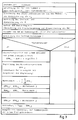
- FIG. 3 shows a possible one Structogram for single cylinder control in a device according to the invention.
- a 6-cylinder diesel engine 1 is shown schematically with six pump nozzles 2-i, the flow control elements are adjustable electromechanically by means of associated servo drives 3-i.
- Such pump nozzles and the drives of their volume control elements are, for example, the subject of DE application 38 11 844 of the applicant, in which reference is also made to DE-A-2845 139 and AT-PS 372 502 in relation to the prior art.
- the invention relates not only to those injection elements in which, for example, a control rod is adjusted, i.e. is shifted or a quantity actuator is rotated, but in general on each controlled injection unit, e.g. also on solenoid valves.
- a speed sensor 5 which scans pins, not shown here, inserted on the flywheel 4 and accordingly delivers pulses during engine rotation which correspond to specific angular positions of the flywheel 4.
- speed sensors are also known and are disclosed, for example, in DE-A-31 22 533 (FIG. 3 and associated description).
- two speed sensors can also be used, wherein the alternator of the vehicle can be used as a speed sensor, as described in DE-A-35 01 435 by the applicant.
- Further sensors 6 are also provided, which provide signals with information about various operating states of the engine 1 or of the vehicle, e.g. Temperature and pressure sensors.
- a needle stroke sensor 7-i is generally provided in each pump nozzle 2-i, which provides information about the position of the valve needle of an injection valve, e.g. in DE-A-37 26 712 of the applicant.
- an electronic controller for the regulation or control of the motor 1, an electronic controller, here called basic controller 8, is known, used.
- a controller contains computing units which calculate an output signal RW from supplied operating variable signals, which, via the servo drives 3-i, determines the current position of the quantity control element of each pump nozzle 2-i and thus the amount of fuel to be injected.
- the operating variable signals of the sensors 6 and 7-i are thus fed to the basic controller 8 and at least one output signal of a speed computer 9, which is an average speed or a corresponding signal n determined.
- the calculation of speed signals or average speeds is also known, reference being made to the applicant's DE application 38 08 819 and the literature cited therein.
- the speed calculator 9 is shown in the general part of the basic controller 8 and only here, for the sake of clarity, separately from it.
- the output signal of an accelerator pedal position sensor 10 is fed to the basic controller.
- a basic controller 8 as used here, generally has a PID control characteristic, as can be seen, for example, from DE-A-27 35 596. It forms, in principle, via which the servo drives 3-i, the motor 1 and the speed sensor 5 form a closed control loop, the actual variable being the average speed n and the target variable in the basic controller 8 is calculated as a function of the supplied operating variable signals, of which of course the signal indicating the accelerator pedal position is an essential signal.
- the middle speed signal becomes a comparator unit 11 n and also a cylinder-specific speed signal n i determined in the speed computer 9.
- This signal n i is determined by measuring the time period T i via the combustion strokes of the individual cylinders, specifically by counting the time in a time counter 12 and generating reciprocal values in a reciprocal value generator 13.
- the time counter 12, the reciprocal value generator 13 and an average value generator 14 are here shown as blocks of the speed calculator 9 (Fig. 2).
- the time is counted between pulses from the speed sensor 5, which correspond to pins on the flywheel 4 and successive top dead centers of the cylinders (in the chronological order of ignition).
- the pulses do not have to correspond exactly to the top dead center, they can each be generated a small angle of rotation before or after the top dead center, but should occur essentially in the vicinity of the top dead center, since in this case the most reliable information about the speed fluctuations is obtained.
- the comparator unit 11 in this exemplary embodiment contains a subtractor 15 to which the middle or cylinder-specific speed signal n or n i are fed, and a signal generator 16 connected downstream of the subtractor, which outputs a change value +1 if n i ⁇ n , and a change value -1 if n i > n . If the cylinder-specific speed n i does not differ from the mean speed, or not significantly n deviates, no change value is output. However, the comparator unit 11 can generally output a change value ⁇ Q i , the size of which also depends on the measure of the deviation between n i and n can depend, as indicated in Fig. 1 at the output of the comparator unit 11 with ⁇ Q i .
- the change values ⁇ Q i form the starting point for the single-cylinder control, because according to these change values the respective cylinders should receive more or less fuel so that uneven running is compensated for.
- a synchronization unit 20 is provided for the necessary synchronization, to which the signal from the speed sensor 5 on the one hand and the signal from at least one of the needle stroke sensors 7-i are supplied on the one hand, so that an absolute, i.e. cylinder-related synchronization is possible.
- an absolute i.e. cylinder-related synchronization is possible.
- another signal can also be used, e.g. is derived from moving engine parts and enables absolute synchronization. If the invention is applied to a gasoline engine, it could e.g. are signals derived from the electrical ignition.
- the synchronizing unit 20 controls the memory control unit 17 by means of a synchronizing signal s in such a way that the change values ⁇ Q i always reach the assigned cylinder memory 19-i.
- a controlled switch 21 This is illustrated in FIG. 2 by a controlled switch 21. 2 also shows a controlled switch 22 which is located between the comparator unit 11 and the memory control unit 17 and is shown here as a multiplier.
- the switch 22 is controlled by a status signal st of the synchronization unit 20. This status signal has the value "0" as long as no synchronization has taken place, which is possible, for example, when starting the engine, and the value "1" if synchronization is present.
- the change values .DELTA.Q i are thus only passed on with existing synchronization.
- the memory area selection unit 18, for example, as shown in FIG. 2, consists of z-controlled switches 23-i, 24-i at the input and at the output of each cylinder memory 19-i, each switch having a k position.
- all z switches 23-i, 24-i are controlled by a speed range discriminator 25, which is the mean speed signal n is fed and connects via the switches 23-i, 24-i to the speed range corresponding to this speed range memory area 19-ij with the input and output of each cylinder memory 19-i.
- the range is thus selected exclusively according to the selection criterion "average engine speed", but other operating variable signals can also be supplied to the function of the memory area selection unit 18, such as a signal r according to FIG.
- Each cylinder memory 19-i thus represents a three-dimensional correction field for each cylinder.
- the cylinder memories 19-i and their memory areas 19-ij are each designed as summing or integrating memories, so that the stored correction value ⁇ RW ij increases or decreases depending on the sign (and size) of the corresponding supplied change value ⁇ Q i .
- the correction values ⁇ RW i may be multiplied in a respective multiplier 27-i with a dynamic adjustment factor K EZR before their supply to a respective summer 26-i, in which they are added to the respective output signal RW of the base regulator 8. This may be advisable due to the digital development of the correction values for numerical reasons.
- the summers 26-i are drawn with an additional subtracting input, to each of which a feedback signal m from an actuator feedback 28-i is supplied.
- the servo drives 3-i namely have an analog servo controller 29-i which acts on the actuator 30-i mechanically connected to the feedback 28. This provides a closed servo circuit for the actuator of each pump nozzle 2-i. With regard to further details of such servo circuits, reference can be made to the applicant's DE-A-37 40 443.
- FIG. 2a A modification of the cylinder memories 19-i is shown in FIG. 2a, in which an interpolation and arithmetic unit 31 is assigned to each memory area 19-ij.
- This unit takes on the one hand the function of the switches 23-i, 24-i of FIG. 2 and on the other hand enables an interpolation between speed bases n j .
- the drift compensator 32 has k summers 33-j (FIG. 2), each summator being supplied with the z correction values of the memory areas 19-ij with the same index j.
- the arithmetic mean value ⁇ RW ij / z is formed in each divider 34-j.
- a subtractor 35-ij 35-ij is connected upstream of each input of each memory area 19-ij, on the one hand the change value ⁇ Q ij determined by the comparator unit 11 and assigned by the selection unit 18 and on the other hand the mean value of the correction values coming from the corresponding divider 34-j is fed.
- the drift compensator 32 is also supplied with an activation signal as (FIG. 1) of the synchronizing unit 20, which occurs in rotation-synchronous fashion, for example every 10 or 20 revolutions, and the actual calculation or output of the arithmetic mean value to the subtracting elements 35-ij causes controlled switches (Not shown) or the like. can be provided.
- the activation signal as can also occur at fixed time intervals, for example every second, in which case it is generated in a clock. It is in no way necessary to carry out the drift compensation with every combustion stroke, so that computing time can be saved for other calculations if the drift compensation is only carried out at intervals at which it is likely to be required.
- FIG. 2 A possible embodiment of the memory areas 19-ij is shown in FIG. 2 for the first cylinder memory 19-1.
- Each memory area 19-1k acts as a digital integrator or totalizer with limitation.
- a limiting unit 36-1j At the input of a limiting unit 36-1j is a summing element 37-1j, on the one hand the output signal of the corresponding subtracting element 35-1j of the drift compensator 32 and on the other hand the output signal of a reset element 38-1j located in the feedback branch of the integrator 19-1j (symbol z ⁇ 1: see Isermann, "Digital Control Systems", Springerverlag, Berlin / Heidelberg 1977). Such memories belong to the prior art.
- Each memory area with limiter unit 36-1j can be set up to emit an indicator signal which occurs if the stored correction value ⁇ RW-ij reaches an upper or lower limit. This is indicated in Fig. 2 for the first cylinder memory 19-1 for a memory area 19-1j with the signal d-1j. All indicator signals d-ij can be supplied with an OR operation and used to trigger an error display or an alarm signal.
- the drawing shows block diagrams with individual function blocks, but in practice, all or most of the function blocks are implemented in software in a microcomputer or a microcomputer system.
- a possible program sequence for this purpose is illustrated in the structure diagram according to FIG. 3, which does not require any further explanation in view of the above explanations.
Landscapes
- Engineering & Computer Science (AREA)
- Chemical & Material Sciences (AREA)
- Combustion & Propulsion (AREA)
- Mechanical Engineering (AREA)
- General Engineering & Computer Science (AREA)
- Electrical Control Of Air Or Fuel Supplied To Internal-Combustion Engine (AREA)
- Output Control And Ontrol Of Special Type Engine (AREA)
Claims (15)
Priority Applications (1)
| Application Number | Priority Date | Filing Date | Title |
|---|---|---|---|
| AT89890172T ATE78898T1 (de) | 1988-07-04 | 1989-06-20 | Einrichtung zum steuern und regeln der brennkraftmaschine eines fahrzeuges. |
Applications Claiming Priority (2)
| Application Number | Priority Date | Filing Date | Title |
|---|---|---|---|
| DE3822582A DE3822582A1 (de) | 1988-07-04 | 1988-07-04 | Einrichtung zum steuern und regeln der brennkraftmaschine eines fahrzeuges |
| DE3822582 | 1988-07-04 |
Publications (2)
| Publication Number | Publication Date |
|---|---|
| EP0353217A1 EP0353217A1 (fr) | 1990-01-31 |
| EP0353217B1 true EP0353217B1 (fr) | 1992-07-29 |
Family
ID=6357912
Family Applications (1)
| Application Number | Title | Priority Date | Filing Date |
|---|---|---|---|
| EP89890172A Expired - Lifetime EP0353217B1 (fr) | 1988-07-04 | 1989-06-20 | Appareil de commande et régulation du moteur à combustion d'un véhicule |
Country Status (4)
| Country | Link |
|---|---|
| EP (1) | EP0353217B1 (fr) |
| AT (1) | ATE78898T1 (fr) |
| DE (2) | DE3822582A1 (fr) |
| ES (1) | ES2034768T3 (fr) |
Families Citing this family (2)
| Publication number | Priority date | Publication date | Assignee | Title |
|---|---|---|---|---|
| DE3906083A1 (de) * | 1989-02-27 | 1990-08-30 | Voest Alpine Automotive | Einrichtung zum steuern und regeln einer dieselbrennkraftmaschine |
| DE10047003A1 (de) * | 2000-09-22 | 2002-04-25 | Bosch Gmbh Robert | Verfahren zum Betreiben einer Brennkraftmaschine |
Family Cites Families (5)
| Publication number | Priority date | Publication date | Assignee | Title |
|---|---|---|---|---|
| US4495920A (en) * | 1982-04-09 | 1985-01-29 | Nippondenso Co., Ltd. | Engine control system and method for minimizing cylinder-to-cylinder speed variations |
| JPS5925055A (ja) * | 1982-08-03 | 1984-02-08 | Nippon Denso Co Ltd | 空燃比制御装置 |
| DE3336028C3 (de) * | 1983-10-04 | 1997-04-03 | Bosch Gmbh Robert | Einrichtung zur Beeinflussung von Steuergrößen einer Brennkraftmaschine |
| JPS6131645A (ja) * | 1984-07-20 | 1986-02-14 | Fuji Heavy Ind Ltd | 自動車用エンジンの電子制御方式 |
| JPS61118535A (ja) * | 1984-11-14 | 1986-06-05 | Nippon Soken Inc | 内燃機関の空燃比制御装置 |
-
1988
- 1988-07-04 DE DE3822582A patent/DE3822582A1/de active Granted
-
1989
- 1989-06-20 DE DE8989890172T patent/DE58901936D1/de not_active Expired - Fee Related
- 1989-06-20 EP EP89890172A patent/EP0353217B1/fr not_active Expired - Lifetime
- 1989-06-20 AT AT89890172T patent/ATE78898T1/de not_active IP Right Cessation
- 1989-06-20 ES ES198989890172T patent/ES2034768T3/es not_active Expired - Lifetime
Also Published As
| Publication number | Publication date |
|---|---|
| ATE78898T1 (de) | 1992-08-15 |
| DE3822582C2 (fr) | 1990-07-19 |
| DE3822582A1 (de) | 1990-02-08 |
| EP0353217A1 (fr) | 1990-01-31 |
| ES2034768T3 (es) | 1993-04-01 |
| DE58901936D1 (de) | 1992-09-03 |
Similar Documents
| Publication | Publication Date | Title |
|---|---|---|
| EP0416270B1 (fr) | Procédé et dispositif pour commander et régler un moteur à auto-allumage | |
| DE102008043165B4 (de) | Verfahren und Vorrichtung zur Kalibrierung der Voreinspritzmenge einer Brennkraftmaschine, insbesondere eines Kraftfahrzeugs | |
| DE69410043T2 (de) | Luft-Kraftstoff-Verhältnis-Regeleinrichtung für eine Brennkraftmaschine | |
| DE2829958C2 (fr) | ||
| DE2458859C2 (fr) | ||
| DE2633617C2 (de) | Verfahren und Vorrichtung zur Bestimmung von Einstellgrößen bei einer Brennkraftmaschine, insbesondere der Dauer von Kraftstoffeinspritzimpulsen, des Zündwinkels, der Abgasrückführrate | |
| DE3336028A1 (de) | Einrichtung zur beeinflussung von steuergroessen einer brennkraftmaschine | |
| DE102008054690A1 (de) | Verfahren und Vorrichtung zur Kalibrierung von Teileinspritzungen in einer Brennkraftmaschine, insbesondere eines Kraftfahrzeugs | |
| DE69524775T2 (de) | Elektronische einrichtung zur erfassung der belastung und drehzahl einer brennkraftmaschine | |
| DE3644639C2 (fr) | ||
| DE3120667A1 (de) | Steuersystem fuer eine fremdgezuendete brennkraftmaschine | |
| DE3725521C2 (fr) | ||
| EP0443147B1 (fr) | Procédé et dispositif pour réguler/commander la stabilité de marche d'un moteur à combustion interne | |
| DE3422384C2 (fr) | ||
| EP0385969B1 (fr) | Dispositif de commande et de régulation d'un moteur diesel | |
| DE3416370C2 (fr) | ||
| EP1015749B1 (fr) | Procede de fonctionnement d'un moteur a combustion interne | |
| DE4319677A1 (de) | Verfahren und Vorrichtung zur Regelung der Laufruhe einer Brennkraftmaschine | |
| DE19612453A1 (de) | Verfahren zum Bestimmen der in das Saugrohr oder in den Zylinder einer Brennkraftmaschine einzubringenden Kraftstoffmasse | |
| EP0353216B1 (fr) | Appareil de commande et régulation du moteur à combustion d'un véhicule | |
| DE3700942C1 (de) | Verfahren zur Regelung der Gemischzusammensetzung bei einer gemischverdichtenden Brennkraftmaschine | |
| EP0353217B1 (fr) | Appareil de commande et régulation du moteur à combustion d'un véhicule | |
| EP0995026B1 (fr) | Procede de fonctionnement d'un moteur a combustion interne | |
| DE69623200T2 (de) | Luft-/Ktaftstoffverhältnis-Steuereinrichtung für Brennkraftmaschine | |
| DE3034069A1 (de) | Regel- und steuereinrichtung fuer die triebstoffzufuhr zu einem brennkraftmotor |
Legal Events
| Date | Code | Title | Description |
|---|---|---|---|
| PUAI | Public reference made under article 153(3) epc to a published international application that has entered the european phase |
Free format text: ORIGINAL CODE: 0009012 |
|
| AK | Designated contracting states |
Kind code of ref document: A1 Designated state(s): AT BE CH DE ES FR GB IT LI NL SE |
|
| 17P | Request for examination filed |
Effective date: 19900306 |
|
| 17Q | First examination report despatched |
Effective date: 19910219 |
|
| RAP1 | Party data changed (applicant data changed or rights of an application transferred) |
Owner name: AUTOMOTIVE DIESEL GESELLSCHAFT M.B.H. |
|
| GRAA | (expected) grant |
Free format text: ORIGINAL CODE: 0009210 |
|
| AK | Designated contracting states |
Kind code of ref document: B1 Designated state(s): AT BE CH DE ES FR GB IT LI NL SE |
|
| REF | Corresponds to: |
Ref document number: 78898 Country of ref document: AT Date of ref document: 19920815 Kind code of ref document: T |
|
| REF | Corresponds to: |
Ref document number: 58901936 Country of ref document: DE Date of ref document: 19920903 |
|
| ET | Fr: translation filed | ||
| ITF | It: translation for a ep patent filed | ||
| GBT | Gb: translation of ep patent filed (gb section 77(6)(a)/1977) | ||
| REG | Reference to a national code |
Ref country code: ES Ref legal event code: FG2A Ref document number: 2034768 Country of ref document: ES Kind code of ref document: T3 |
|
| PLBE | No opposition filed within time limit |
Free format text: ORIGINAL CODE: 0009261 |
|
| STAA | Information on the status of an ep patent application or granted ep patent |
Free format text: STATUS: NO OPPOSITION FILED WITHIN TIME LIMIT |
|
| 26N | No opposition filed | ||
| EAL | Se: european patent in force in sweden |
Ref document number: 89890172.3 |
|
| PGFP | Annual fee paid to national office [announced via postgrant information from national office to epo] |
Ref country code: GB Payment date: 19960516 Year of fee payment: 8 |
|
| PGFP | Annual fee paid to national office [announced via postgrant information from national office to epo] |
Ref country code: DE Payment date: 19960517 Year of fee payment: 8 |
|
| PGFP | Annual fee paid to national office [announced via postgrant information from national office to epo] |
Ref country code: FR Payment date: 19960521 Year of fee payment: 8 |
|
| PGFP | Annual fee paid to national office [announced via postgrant information from national office to epo] |
Ref country code: SE Payment date: 19960523 Year of fee payment: 8 Ref country code: AT Payment date: 19960523 Year of fee payment: 8 |
|
| PGFP | Annual fee paid to national office [announced via postgrant information from national office to epo] |
Ref country code: CH Payment date: 19960524 Year of fee payment: 8 Ref country code: BE Payment date: 19960524 Year of fee payment: 8 |
|
| PGFP | Annual fee paid to national office [announced via postgrant information from national office to epo] |
Ref country code: NL Payment date: 19960529 Year of fee payment: 8 |
|
| PGFP | Annual fee paid to national office [announced via postgrant information from national office to epo] |
Ref country code: ES Payment date: 19960618 Year of fee payment: 8 |
|
| PG25 | Lapsed in a contracting state [announced via postgrant information from national office to epo] |
Ref country code: GB Free format text: LAPSE BECAUSE OF NON-PAYMENT OF DUE FEES Effective date: 19970620 Ref country code: AT Effective date: 19970620 |
|
| PG25 | Lapsed in a contracting state [announced via postgrant information from national office to epo] |
Ref country code: SE Effective date: 19970621 Ref country code: ES Free format text: LAPSE BECAUSE OF NON-PAYMENT OF DUE FEES Effective date: 19970621 |
|
| PG25 | Lapsed in a contracting state [announced via postgrant information from national office to epo] |
Ref country code: LI Free format text: LAPSE BECAUSE OF NON-PAYMENT OF DUE FEES Effective date: 19970630 Ref country code: CH Free format text: LAPSE BECAUSE OF NON-PAYMENT OF DUE FEES Effective date: 19970630 Ref country code: BE Effective date: 19970630 |
|
| BERE | Be: lapsed |
Owner name: AUTOMOTIVE DIESEL G.M.B.H. Effective date: 19970630 |
|
| PG25 | Lapsed in a contracting state [announced via postgrant information from national office to epo] |
Ref country code: NL Effective date: 19980101 |
|
| GBPC | Gb: european patent ceased through non-payment of renewal fee |
Effective date: 19970620 |
|
| REG | Reference to a national code |
Ref country code: CH Ref legal event code: PL |
|
| PG25 | Lapsed in a contracting state [announced via postgrant information from national office to epo] |
Ref country code: FR Free format text: LAPSE BECAUSE OF NON-PAYMENT OF DUE FEES Effective date: 19980227 |
|
| EUG | Se: european patent has lapsed |
Ref document number: 89890172.3 |
|
| NLV4 | Nl: lapsed or anulled due to non-payment of the annual fee |
Effective date: 19980101 |
|
| PG25 | Lapsed in a contracting state [announced via postgrant information from national office to epo] |
Ref country code: DE Free format text: LAPSE BECAUSE OF NON-PAYMENT OF DUE FEES Effective date: 19980303 |
|
| REG | Reference to a national code |
Ref country code: FR Ref legal event code: ST |
|
| REG | Reference to a national code |
Ref country code: FR Ref legal event code: ST |
|
| REG | Reference to a national code |
Ref country code: ES Ref legal event code: FD2A Effective date: 20000403 |
|
| PG25 | Lapsed in a contracting state [announced via postgrant information from national office to epo] |
Ref country code: IT Free format text: LAPSE BECAUSE OF NON-PAYMENT OF DUE FEES;WARNING: LAPSES OF ITALIAN PATENTS WITH EFFECTIVE DATE BEFORE 2007 MAY HAVE OCCURRED AT ANY TIME BEFORE 2007. THE CORRECT EFFECTIVE DATE MAY BE DIFFERENT FROM THE ONE RECORDED. Effective date: 20050620 |