EP0353365B1 - Ultraschall-Zellzerstörer - Google Patents
Ultraschall-Zellzerstörer Download PDFInfo
- Publication number
- EP0353365B1 EP0353365B1 EP88308544A EP88308544A EP0353365B1 EP 0353365 B1 EP0353365 B1 EP 0353365B1 EP 88308544 A EP88308544 A EP 88308544A EP 88308544 A EP88308544 A EP 88308544A EP 0353365 B1 EP0353365 B1 EP 0353365B1
- Authority
- EP
- European Patent Office
- Prior art keywords
- container
- ultrasonic
- cells
- containers
- destroyer
- Prior art date
- Legal status (The legal status is an assumption and is not a legal conclusion. Google has not performed a legal analysis and makes no representation as to the accuracy of the status listed.)
- Expired - Lifetime
Links
Images


Classifications
-
- C—CHEMISTRY; METALLURGY
- C12—BIOCHEMISTRY; BEER; SPIRITS; WINE; VINEGAR; MICROBIOLOGY; ENZYMOLOGY; MUTATION OR GENETIC ENGINEERING
- C12N—MICROORGANISMS OR ENZYMES; COMPOSITIONS THEREOF; PROPAGATING, PRESERVING, OR MAINTAINING MICROORGANISMS; MUTATION OR GENETIC ENGINEERING; CULTURE MEDIA
- C12N1/00—Microorganisms; Compositions thereof; Processes of propagating, maintaining or preserving microorganisms or compositions thereof; Processes of preparing or isolating a composition containing a microorganism; Culture media therefor
- C12N1/06—Lysis of microorganisms
- C12N1/066—Lysis of microorganisms by physical processes
-
- C—CHEMISTRY; METALLURGY
- C12—BIOCHEMISTRY; BEER; SPIRITS; WINE; VINEGAR; MICROBIOLOGY; ENZYMOLOGY; MUTATION OR GENETIC ENGINEERING
- C12M—APPARATUS FOR ENZYMOLOGY OR MICROBIOLOGY; APPARATUS FOR CULTURING MICROORGANISMS FOR PRODUCING BIOMASS, FOR GROWING CELLS OR FOR OBTAINING FERMENTATION OR METABOLIC PRODUCTS, i.e. BIOREACTORS OR FERMENTERS
- C12M47/00—Means for after-treatment of the produced biomass or of the fermentation or metabolic products, e.g. storage of biomass
- C12M47/06—Hydrolysis; Cell lysis; Extraction of intracellular or cell wall material
Definitions
- the present invention relates to an ultrasonic cell-destroyer, and particularly to an apparatus for destroying cells floating in a solution in a closed container by radiating ultrasonic waves to the solution in the container, thereby subjecting the floating cells to impacts and/or cavitations caused by the radiation of ultrasonic waves and destroying them.
- destruction of cells means that the outer membrane of each cell is broken to remove its minute organs or organelles.
- an ultrasonic cell-destroyer has been used for this purpose.
- an ultrasonic generator horn or tip is soaked in the cell-suspended solution in an open container, such as a test glass or test cup. Then, the vibrator of the ultrasonic generator is vibrated by an associated high-frequency oscillator, thereby subjecting the cells to the radiation of the ultrasonic wave in the solution so that their membranes may be broken by force caused by cavitation.
- an ultrasonic cell-destroyer comprising at least one closed container comprising a container body and a closure for containing a given quantity of liquid in which cells to be destroyed are suspended, and a vessel equipped with ultrasonic wave generator means at its bottom so as to destroy cells in the container, which is partly soaked in the bath of the vessel, characterised in that the container body has an upward converging or concave groove on its bottom end.
- the container body may have a tapering shape converging towards its bottom end.
- the bottom end on which a groove is formed may have a semispherical shape.
- the apparatus may comprise a rotatable disk having the plurality of apertures in which the containers are to be fitted, the disk being laid above the surface of the bath in the vessel, and means for rotating the disk slowly, thereby permitting the containers to travel circular paths while being exposed to the radiation of ultrasonic wave in the bath.
- Said means for rotating the disk slowly may be an electric motor, otherwise, it may be a manually operated device.
- the disk may comprise circular floor and ceiling plates and a circumferential wall integrally connected to the floor plate.
- the floor plate has a plurality of apertures in which the containers are to be fitted, and the ceiling plate is used as a closure to define a closed space along with the floor plate and the circumferential wall. Then, the clearance between the ceiling and the top surface of the closure of the container provides a space which permits efficient generation of resonance from ultrasonic energy in the container, thereby making full use of the ultrasonic energy to destroy the cells in the container.
- Each container has an upward converging or concave groove at its bottom, and the ultrasonic energy is apt to converge to the reentrant portion of the bottom of the container.
- the solution in which cells to be destroyed are suspended is put in the bottom portion of the container, and therefore effective destruction can be performed.
- the rod-free container is useful in destroying a very small amount of cell in the solution, and it facilitates subsequent centrifugal separation. In case of fitting a plurality of containers in the apertures of a rotary disk, cells suspended in the solutions in these containers can be equally destroyed.
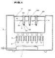
- FIG.s 1 to 4 there is shown an ultrasonic cell-destroyer according to a first embodiment of the present invention.
- the cell-destroyer comprises, in a casing 5, a high-frequency oscillator 1, vibrating elements 2 such as ferrite magnetostriction vibrating elements each equipped with a driving coil 3, which is energised by the high-frequency oscillator 1, and a vessel 4 filled with liquid W.
- vibrating elements 2 such as ferrite magnetostriction vibrating elements each equipped with a driving coil 3, which is energised by the high-frequency oscillator 1, and a vessel 4 filled with liquid W.
- a closure plate 21 has a plurality of apertures 22a, 22b, 23c,...therein, and a closed container 12 is fitted in each aperture.
- Each closed container comprises a closure cap 12a and a container body 12c with an upward converging groove 12e on its bottom 12d.
- One example of the container as shown in Figs. 2 and 3 has a container body 12c generally tapering to its bottom end 12d, and the bottom end has an upward concave groove 12e.
- Another example of the container as shown in Fig. 4 has a container body 12c rounded at its bottom end 12d, and likewise, the bottom end 12d has an upward concave groove 12e.
- the container body 12c may be preferably made of a very hard material, and it can be made of polymethylpentene resin, polypropylene, acrylics, high-density polyethylene or polystyrene.
- cells to be destroyed are put in a solution, and then the solution is put in a container body 12c.
- the solution is indicated at T.
- the container body 12c is closed with a closure cap 12a.
- a plurality of containers thus filled with solution are fitted in the apertures 22a, 22b, 22c... Then, these containers are partly soaked in the liquid bath W in the vessel 4 so that the level of the solution T in each container may be brought under the surface of the bath W.
- the ultrasonic oscillator is operated to radiate ultrasonic waves into the bath.
- each container is vibrated at its intrinsic or natural frequency, and that the resonance of the container body generates a secondary vibration in the solution T in the container body, thereby causing cavitation in the solution to destroy the cells. Otherwise, it is supposed that the resonance of the container body causes the solution T in the container to vigorously vibrate, thereby repeatedly throwing cells against the inner surface of the bottom 12d of the container body 12c until they are destroyed.
- the upward concave groove 12e formed at the center of the bottom 12d of the container 12 has the effect of directing the ultrasonic energy available to the center of the bottom 12d of the container 12. As a result the bottom 12d is supposed to be put in so vigorous vibration that the solution T is repeatedly thrown against the surrounding bottom wall of the container, thereby destroying cells, which are suspended in the solution.
- the container 12 uses no rod, and therefore its size can be reduced to be appropriate for containing and destroying a very small quantity of cells.
- the size of the rod-free container can be increased to meet destruction of a relatively large quantity of cells. Thanks to the absence of a rod in the container, it can be subjected to centrifugal separation subsequent to the ultrasonic destruction of cells, which is conducted around the upward convergent bottom of the container at an increased efficiency.
- Figs. 5 to 8 show an ultrasonic cell-destroyer according to a second embodiment of the present invention.
- the same parts of the ultrasonic cell-vibrator as appear in Figs.1 to 4 are indicated by the same reference numerals, and explanation of these parts used in common are omitted.
- the ultrasonic cell-vibrator according to the second embodiment has a ceiling plate 6 integrally connected to its vessel 4.
- the ceiling plate 6 has a center opening.
- An electric motor 13 is mounted to the ceiling plate 6.
- a gear wheel plate 7 is rotatably laid across the center opening of the ceiling plate 6, and it is connected to the shaft of the electric motor 13 via an intermediate gear wheel 14.
- the gear wheel plate 7 has a holder rod 8 fixed thereto with nuts 16.
- the holder rod 8 has threads at its upper and lower portions 8a and 8b. It is threadedly connected to the gear wheel plate 7 at its upper threads 8a to adjust the level at which a rotary container-holder 9 is held with respect to the surface level of the bath in the vessel, as later described in detail.
- the rotary container-holder 9 is circular in shape, and is smaller than the gear wheel plate 7 in diameter, and is threadedly engaged with the lower part of the holder rod 8. It comprises circular floor and ceiling plates 11a and 10 and a circumferential wall 11 integrally connected to the floor plate 11a.
- the floor plate 11a has a plurality of apertures 11b in which the containers 12 are to be fitted.
- the ceiling plate 10 has a center hole to allow the lower length of the holder rod 8 to pass therethrough, and the floor plate 11a has a center female-threaded hole to permit the lower male-threaded part 8b of the holder rod 8 to engage with the floor plate 11a as indicated at 15. As shown in Figs.
- the ceiling plate 10 is used as a closure to define a closed space along with the floor plate 11a and the circumferential wall 11, leaving the clearance S between the ceiling 10a and the top surface 12b of the container 12, thus providing a space which permits efficient generation of resonance from ultrasonic energy in the containers 12 to make full use of the ultrasonic energy to available to destroy cells in the containers 12.
- a solution in which cells to be destroyed are suspended is put in a plurality of containers 12, and then these containers 12 are closed with their cap closures 12a.
- the ceiling plate 10 is removed, and then the containers are fitted in the apertures 11b of the floor plate 11a.
- the ceiling plate 10 is put on the circumferential wall 11, and they are integrally connected by screwing the male-threaded lower part 8b of the holder rod 8 in the female-threaded hole 15 of the floor plate 11a.
- the clearance S is left between the ceiling 10a and the top surface 12b of the container 12 to provide a space which permits efficient generation of resonance from ultrasonic energy in the containers 12.
- the rotary container-holder disk having the containers 12 mounted therein is suspended from the gear wheel plate 7. Then, the containers are partly soaked in the bath W in the vessel 4 so that the level of the solution T in the containers 12 may be below the surface level of the bath W.
- the ultrasonic wave is transmitted in the bath W to reach the containers 12, causing these containers to vibrate at its resonant frequency to destroy cells in the containers 12 in the same way as in the ultrasonic cell-destroyer according to the first embodiment described above. It appears that thanks to the clearance S between the ceiling 10a and the top level of the closed containers 12 a strong resonance is caused in each closed container to produce cavitation in the solution and destroy cells therein.
- the rotary container-holder 9 is rotated at a given constant velocity by the electric motor 13, thereby equally exposing the closed containers 12 to ultrasonic radiation, thereby assuring that the cells in every container are evenly destroyed.
- a plurality of apertures 11b in which containers 12 are to be fitted are made in the floor plate 11a of the rotary container-holder 9.
- a plurality of apertures may be made in the gear wheel plate 7.
- an ultrasonic cell-destroyer uses no elongated rod to be put in a container in which cell-suspending solution is put, and therefore the container size can be reduced to be appropriate for the purpose of destroying a very small quantity of cell-suspending solution.
- the use of rod-free container facilitates subsequent treatment, such as centrifugal separation of destroyed cells.
- the groove of the container bottom permits convergence of ultrasonic energy to the center of the container bottom, thereby making full use of the ultrasonic energy available to destroy cells in the containers. Also, cells suspended in the solutions in a plurality of containers can be equally destroyed.
Landscapes
- Life Sciences & Earth Sciences (AREA)
- Engineering & Computer Science (AREA)
- Health & Medical Sciences (AREA)
- Chemical & Material Sciences (AREA)
- Bioinformatics & Cheminformatics (AREA)
- Wood Science & Technology (AREA)
- Organic Chemistry (AREA)
- Biotechnology (AREA)
- Zoology (AREA)
- Genetics & Genomics (AREA)
- General Health & Medical Sciences (AREA)
- Microbiology (AREA)
- Biomedical Technology (AREA)
- Biochemistry (AREA)
- General Engineering & Computer Science (AREA)
- Medicinal Chemistry (AREA)
- Cell Biology (AREA)
- Molecular Biology (AREA)
- Mycology (AREA)
- Sustainable Development (AREA)
- Tropical Medicine & Parasitology (AREA)
- Virology (AREA)
- Apparatus Associated With Microorganisms And Enzymes (AREA)
- Micro-Organisms Or Cultivation Processes Thereof (AREA)
- Disintegrating Or Milling (AREA)
- Distillation Of Fermentation Liquor, Processing Of Alcohols, Vinegar And Beer (AREA)
- Water Treatment By Sorption (AREA)
Claims (7)
- Ultraschallzellzerstörer, umfassend:
wenigstens einen geschlossenen Behälter (12) mit einem Behälterkörper (12c) und einem Deckel (12a) zur Aufnahme einer gegebenen Menge Flüssigkeit (T), in der zu zerstörende Zellen suspendiert sind, und ein Gefäß (4), das an seinem Boden mit einem Erzeugermittel für Ultraschallwellen versehen ist, um Zellen in dem Behälter (12) zu zerstören, der in das Bad (W) des Gefäßes (4) teilweise eingetaucht ist, dadurch gekennzeichnet, daß der Behälterkörper (12c) an seinem Bodenende (12d) eine nach oben konvergierende oder konkave Aussparung (12e) aufweist. - Ultraschallzellzerstörer nach Anspruch 1, dadurch gekennzeichnet, daß der Behälterkörper (12c) eine zu seinem Bodenende (12d) konvergierende zugespitzte Form hat.
- Ultraschallzerstörer nach Anspruch 1, dadurch gekennzeichnet, daß das mit einer Aussparung versehene Bodenende (12d) eine halbkugelige Form hat.
- Ultraschallzerstörer nach Anspruch 1, 2 oder 3, dadurch gekennzeichnet, daß er weiter umfasst: eine drehbare Scheibe (11) mit mehreren Öffnungen (11b) zur eng passenden Aufnahme der Behälter, welche Scheibe an dem Gefäß drehbar angebracht ist und über der Oberfläche des Bads (W) in dem Gefäß (4) liegt, und ein Mittel zum langsamen Drehen der Scheibe (11), so daß die Behälter auf Kreisbahnen bewegt werden können, während sie der Ultraschallwellenstrahlung in dem Bad ausgesetzt sind.
- Ultraschallzerstörer nach Anspruch 4, in dem das Mittel zum langsamen Drehen der Scheibe (11) ein Elektromotor (13) ist.
- Ultraschallzerstörer nach Anspruch 4, dadurch gekennzeichnet, daß das Mittel zum langsamen Drehen der Scheibe (11) manuell betätigt ist.
- Ultraschallzerstörer nach einem der Ansprüche 4 bis 6, dadurch gekennzeichnet, daß die Scheibe (11) eine kreisförmige Bodenplatte (11a) und eine Deckplatte (10) und eine mit der Bodenplatte (11a) integral verbundene Umfangswand (11) aufweist, wobei die Bodenplatte (11a) mehrere Öffnungen (11b) aufweist, in die die Behälter (12) eingesetzt werden können, und wobei die Deckplatte (10) als Abdeckung verwendet wird, die zusammen mit der Bodenplatte (11a) und der Umfangswand (11) einen geschlossenem Raum bildet, wobei der Abstand (S) zwischen der Deckplatte (10a) und der oberen Fläche (12b) des Deckels (12a) des Behälters (12) zur Bildung eines Raums bestimmt ist, der eine wirksame Resonanzerzeugung von Ultraschallenergie in dem Behälter (12) erlaubt, um hierdurch die Ultraschallenergie zur Zerstörung der Zellen in dem Behälter (12) vollständig auszunutzen.
Priority Applications (1)
| Application Number | Priority Date | Filing Date | Title |
|---|---|---|---|
| AT88308544T ATE89859T1 (de) | 1988-08-01 | 1988-09-09 | Ultraschall-zellzerstoerer. |
Applications Claiming Priority (2)
| Application Number | Priority Date | Filing Date | Title |
|---|---|---|---|
| JP63192223A JP2671135B2 (ja) | 1988-08-01 | 1988-08-01 | 細胞の超音波破砕装置 |
| JP192223/88 | 1988-08-01 |
Publications (3)
| Publication Number | Publication Date |
|---|---|
| EP0353365A2 EP0353365A2 (de) | 1990-02-07 |
| EP0353365A3 EP0353365A3 (de) | 1991-01-16 |
| EP0353365B1 true EP0353365B1 (de) | 1993-05-26 |
Family
ID=16287711
Family Applications (1)
| Application Number | Title | Priority Date | Filing Date |
|---|---|---|---|
| EP88308544A Expired - Lifetime EP0353365B1 (de) | 1988-08-01 | 1988-09-15 | Ultraschall-Zellzerstörer |
Country Status (6)
| Country | Link |
|---|---|
| US (1) | US4874137A (de) |
| EP (1) | EP0353365B1 (de) |
| JP (1) | JP2671135B2 (de) |
| AT (1) | ATE89859T1 (de) |
| DE (2) | DE3881390T2 (de) |
| ES (1) | ES2014953A4 (de) |
Families Citing this family (44)
| Publication number | Priority date | Publication date | Assignee | Title |
|---|---|---|---|---|
| US5464773A (en) * | 1994-03-14 | 1995-11-07 | Amoco Corporation | Cell disrupting apparatus |
| US6071480A (en) * | 1994-12-22 | 2000-06-06 | Abbott Laboratories | Method for generating a standing sonic wave, methods of sonication with a standing sonic wave, and a standing sonic wave sonicator |
| US5942425A (en) * | 1996-03-12 | 1999-08-24 | Walters; Adriann H. | Method to access nucleic acids from cells |
| WO1998055605A1 (en) * | 1997-06-04 | 1998-12-10 | William Drewes | Method of destroying cells via resonant destruction of intracellular structures |
| US6168100B1 (en) | 1997-10-23 | 2001-01-02 | Toyota Jidosha Kabushiki Kaisha | Method for producing embossed metallic flakelets |
| DE19820466C2 (de) * | 1998-05-07 | 2002-06-13 | Fraunhofer Ges Forschung | Vorrichtung und Verfahren zur gezielten Beaufschlagung einer biologischen Probe mit Schallwellen |
| US6431476B1 (en) * | 1999-12-21 | 2002-08-13 | Cepheid | Apparatus and method for rapid ultrasonic disruption of cells or viruses |
| US7510625B2 (en) * | 1999-03-23 | 2009-03-31 | Dynawave Corporation | Device and method of using explosive forces in a contained environment |
| US6176970B1 (en) | 1999-03-23 | 2001-01-23 | Dynawave Corporation | Device and method of using explosive forces in a contained liquid environment |
| US20040200909A1 (en) * | 1999-05-28 | 2004-10-14 | Cepheid | Apparatus and method for cell disruption |
| US8815521B2 (en) | 2000-05-30 | 2014-08-26 | Cepheid | Apparatus and method for cell disruption |
| JP4078073B2 (ja) | 1999-05-28 | 2008-04-23 | シーフィード | 流体試料分析装置および方法 |
| US9073053B2 (en) | 1999-05-28 | 2015-07-07 | Cepheid | Apparatus and method for cell disruption |
| US6578659B2 (en) * | 2000-12-01 | 2003-06-17 | Misonix Incorporated | Ultrasonic horn assembly |
| JP4594539B2 (ja) * | 2001-02-08 | 2010-12-08 | 日本曹達株式会社 | 攪拌方法 |
| KR100404606B1 (ko) * | 2001-08-06 | 2003-11-05 | 주식회사 토이랩 | 디엔에이 절단 장치 및 그 프로그래밍 방법 |
| US6880771B2 (en) * | 2002-02-01 | 2005-04-19 | Monsanto Technology Llc | Axially reciprocating tubular ball mill grinding device and method |
| US7004282B2 (en) * | 2002-10-28 | 2006-02-28 | Misonix, Incorporated | Ultrasonic horn |
| RU2234376C1 (ru) * | 2003-01-29 | 2004-08-20 | Институт горного дела Дальневосточного отделения РАН | Многоуровневая установка для дезинтеграции глинистого материала |
| GB2403729A (en) * | 2003-07-11 | 2005-01-12 | Qinetiq Ltd | Sonicator device and method |
| CA2548534C (en) | 2003-10-28 | 2014-01-07 | Allosource | Methods for determining microbial contamination of allograft products |
| US7931611B2 (en) * | 2005-03-23 | 2011-04-26 | Misonix, Incorporated | Ultrasonic wound debrider probe and method of use |
| DE102006032637A1 (de) * | 2006-07-13 | 2008-01-17 | Qiagen Gmbh | Vorrichtung zum Aufschluß einer biologischen Probe |
| US20080058775A1 (en) * | 2006-08-29 | 2008-03-06 | Darian Alexander L | Ultrasonic debrider probe and method of use |
| DE102008021000A1 (de) * | 2008-04-25 | 2009-10-29 | Qiagen Gmbh | Verfahren und Vorrichtung zum Aufschluss von biologischem Material |
| US7857243B2 (en) * | 2008-09-03 | 2010-12-28 | Exland Biotech Inc. | High frequency disintegrator |
| CA2752715C (en) * | 2009-04-14 | 2018-05-01 | Arie R. Van Doorn | Hifu induced cavitation with reduced power threshold |
| EP3357579A1 (de) | 2009-04-15 | 2018-08-08 | Biocartis NV | Kartusche zur optischen analyse durch eine bioanalytische reaktionsvorrichtung |
| KR20120012468A (ko) | 2009-04-15 | 2012-02-10 | 비오까르띠 에스아 | rtPCR 반응을 모니터링하기 위한 광학 검출 시스템 |
| EP2427270B1 (de) | 2009-05-06 | 2015-04-01 | Biocartis NV | Vorrichtung zum schneiden eines probenträgers |
| EP2511380B1 (de) | 2011-04-15 | 2013-12-25 | Diagenode S.A. | Verfahren und Vorrichtung zum Fragmentieren von DNA-Sequenzen |
| EP2532433A1 (de) * | 2011-06-06 | 2012-12-12 | Koninklijke Philips Electronics N.V. | Vorrichtung zum Fragmentieren von Molekülen einer Probe durch Ultraschall |
| AU2013204792B2 (en) * | 2012-10-08 | 2014-09-18 | Liquitab Systems Limited | Apparatus method and system for disintegration of a solid |
| CN103060930A (zh) * | 2012-12-24 | 2013-04-24 | 东北林业大学 | 连续化超声法制备天然纳米纤维的设备及方法 |
| US9587236B2 (en) | 2013-01-18 | 2017-03-07 | Folim G. Halaka | Continuous sonication for biotechnology applications and biofuel production |
| EP3169451B1 (de) | 2014-07-17 | 2020-04-01 | University of Washington | Ultraschallsystem zum scheren von zellmaterial |
| BE1024657B1 (fr) | 2016-10-18 | 2018-05-22 | Diagenode Sa | Support pour tubes d'échantillon pour la sonication d'un matériel biologique |
| US10913931B1 (en) * | 2017-01-31 | 2021-02-09 | Glenn Polansky | Apparatus and method for harvesting and preparing viable stem cells |
| JP2021003670A (ja) * | 2019-06-26 | 2021-01-14 | 次郎 三箇 | 超音波処理方法及び装置 |
| EP4037802B1 (de) * | 2019-10-02 | 2026-04-01 | Cellsonics Inc. | Kartusche zur verarbeitung von biologischen proben und methoden davon |
| AU2021252180B2 (en) * | 2020-04-06 | 2024-09-12 | Shaheen Innovations Holding Limited | Cell lysis systems and methods |
| GEP20247656B (en) * | 2020-04-06 | 2024-08-26 | Shaheen Innovations Holding Ltd | Cell lysis systems and methods |
| CA3180786A1 (en) | 2020-06-01 | 2021-05-28 | Imad Lahoud | An infectious disease screening system |
| KR20230034987A (ko) | 2020-06-01 | 2023-03-10 | 샤힌 이노베이션즈 홀딩 리미티드 | 감염증 스크리닝 장치 |
Family Cites Families (4)
| Publication number | Priority date | Publication date | Assignee | Title |
|---|---|---|---|---|
| US2738172A (en) * | 1952-11-28 | 1956-03-13 | Nat Dairy Res Lab Inc | Apparatus for treatment of products with ultrasonic energy |
| JPS55756A (en) * | 1979-01-24 | 1980-01-07 | Nippon Mining Co Ltd | Residual oil cracker |
| US4295613A (en) * | 1979-10-03 | 1981-10-20 | Vpi Educational Foundation | Apparatus for breaking bacterial cells |
| JPS5987669U (ja) * | 1982-12-06 | 1984-06-13 | 東湘電機株式会社 | 超音波細胞破砕装置における容器 |
-
1988
- 1988-08-01 JP JP63192223A patent/JP2671135B2/ja not_active Expired - Lifetime
- 1988-09-09 ES ES88308544T patent/ES2014953A4/es active Pending
- 1988-09-09 AT AT88308544T patent/ATE89859T1/de not_active IP Right Cessation
- 1988-09-09 DE DE8888308544T patent/DE3881390T2/de not_active Expired - Fee Related
- 1988-09-15 EP EP88308544A patent/EP0353365B1/de not_active Expired - Lifetime
- 1988-09-15 DE DE88308544T patent/DE353365T1/de active Pending
- 1988-11-14 US US07/270,217 patent/US4874137A/en not_active Expired - Lifetime
Also Published As
| Publication number | Publication date |
|---|---|
| ES2014953A4 (es) | 1990-08-01 |
| EP0353365A2 (de) | 1990-02-07 |
| DE3881390D1 (de) | 1993-07-01 |
| EP0353365A3 (de) | 1991-01-16 |
| US4874137A (en) | 1989-10-17 |
| ATE89859T1 (de) | 1993-06-15 |
| JPH0240244A (ja) | 1990-02-09 |
| JP2671135B2 (ja) | 1997-10-29 |
| DE353365T1 (de) | 1990-09-06 |
| DE3881390T2 (de) | 1993-09-09 |
Similar Documents
| Publication | Publication Date | Title |
|---|---|---|
| EP0353365B1 (de) | Ultraschall-Zellzerstörer | |
| US7329039B2 (en) | Systems and methods for determining a state of fluidization and/or a state of mixing | |
| US8263005B2 (en) | Methods and systems for modulating acoustic energy delivery | |
| US4901709A (en) | Shock wave source | |
| US3942531A (en) | Apparatus for breaking-up, without contact, concrements present in the body of a living being | |
| US4442852A (en) | Ultrasonic cleaner apparatus | |
| Bendicho et al. | Ultrasound extractions | |
| RU2007133546A (ru) | Устройство и способ ультразвуковой очистки и дезинфекции | |
| JP2006180756A (ja) | 超音波細胞破砕装置 | |
| KR20090094293A (ko) | 유체의 연속 흐름을 처리하기 위한 초음파 방법 및 장치 | |
| JP2009274055A (ja) | メタルフィルター及びそれを利用した携帯用水分供給器 | |
| JP3092396U (ja) | 交差超音波破砕器 | |
| JP2018038305A (ja) | 生物組織破砕容器 | |
| WO2010127434A1 (en) | Magnetic homogenizer apparatus | |
| JPWO2014038373A1 (ja) | 遠心機、及び材料処理方法 | |
| CN115956116A (zh) | 超声设备和使用方法 | |
| TW201912260A (zh) | 超音波產生器、洗淨裝置、萃取裝置 | |
| JPS627830B2 (de) | ||
| CN102016000B (zh) | 用于分解生物材料的方法和装置 | |
| JPH0248033Y2 (de) | ||
| JPS5855756A (ja) | 超音波による細胞の破砕装置 | |
| JP4373391B2 (ja) | 試料破砕用具 | |
| WO2001046714A1 (en) | Ultrasonic horn assembly | |
| KR102560975B1 (ko) | 초음파를 이용하여 화장품을 활성화시키는 코스메틱 부스터 용기 | |
| JPS6343650U (de) |
Legal Events
| Date | Code | Title | Description |
|---|---|---|---|
| PUAI | Public reference made under article 153(3) epc to a published international application that has entered the european phase |
Free format text: ORIGINAL CODE: 0009012 |
|
| AK | Designated contracting states |
Kind code of ref document: A2 Designated state(s): AT BE CH DE ES FR GB GR IT LI LU NL SE |
|
| TCNL | Nl: translation of patent claims filed | ||
| ITCL | It: translation for ep claims filed |
Representative=s name: SOCIETA' ITALIANA BREVETTI S.P.A. |
|
| EL | Fr: translation of claims filed | ||
| DET | De: translation of patent claims | ||
| PUAL | Search report despatched |
Free format text: ORIGINAL CODE: 0009013 |
|
| AK | Designated contracting states |
Kind code of ref document: A3 Designated state(s): AT BE CH DE ES FR GB GR IT LI LU NL SE |
|
| 17P | Request for examination filed |
Effective date: 19910703 |
|
| 17Q | First examination report despatched |
Effective date: 19921103 |
|
| GRAA | (expected) grant |
Free format text: ORIGINAL CODE: 0009210 |
|
| AK | Designated contracting states |
Kind code of ref document: B1 Designated state(s): AT BE CH DE ES FR GB GR IT LI LU NL SE |
|
| PG25 | Lapsed in a contracting state [announced via postgrant information from national office to epo] |
Ref country code: SE Effective date: 19930526 Ref country code: NL Effective date: 19930526 Ref country code: LI Effective date: 19930526 Ref country code: GR Free format text: LAPSE BECAUSE OF FAILURE TO SUBMIT A TRANSLATION OF THE DESCRIPTION OR TO PAY THE FEE WITHIN THE PRESCRIBED TIME-LIMIT Effective date: 19930526 Ref country code: CH Effective date: 19930526 Ref country code: AT Effective date: 19930526 |
|
| REF | Corresponds to: |
Ref document number: 89859 Country of ref document: AT Date of ref document: 19930615 Kind code of ref document: T |
|
| REF | Corresponds to: |
Ref document number: 3881390 Country of ref document: DE Date of ref document: 19930701 |
|
| ET | Fr: translation filed | ||
| ITF | It: translation for a ep patent filed | ||
| REG | Reference to a national code |
Ref country code: CH Ref legal event code: PL |
|
| PG25 | Lapsed in a contracting state [announced via postgrant information from national office to epo] |
Ref country code: ES Free format text: LAPSE BECAUSE OF FAILURE TO SUBMIT A TRANSLATION OF THE DESCRIPTION OR TO PAY THE FEE WITHIN THE PRESCRIBED TIME-LIMIT Effective date: 19930906 |
|
| PG25 | Lapsed in a contracting state [announced via postgrant information from national office to epo] |
Ref country code: LU Free format text: LAPSE BECAUSE OF NON-PAYMENT OF DUE FEES Effective date: 19930930 |
|
| NLV1 | Nl: lapsed or annulled due to failure to fulfill the requirements of art. 29p and 29m of the patents act | ||
| RIN2 | Information on inventor provided after grant (corrected) |
Free format text: CHIBA, SHIGERU |
|
| PLBE | No opposition filed within time limit |
Free format text: ORIGINAL CODE: 0009261 |
|
| STAA | Information on the status of an ep patent application or granted ep patent |
Free format text: STATUS: NO OPPOSITION FILED WITHIN TIME LIMIT |
|
| 26N | No opposition filed | ||
| PGFP | Annual fee paid to national office [announced via postgrant information from national office to epo] |
Ref country code: FR Payment date: 19980828 Year of fee payment: 11 |
|
| PGFP | Annual fee paid to national office [announced via postgrant information from national office to epo] |
Ref country code: DE Payment date: 19980915 Year of fee payment: 11 |
|
| PGFP | Annual fee paid to national office [announced via postgrant information from national office to epo] |
Ref country code: BE Payment date: 19980923 Year of fee payment: 11 |
|
| PGFP | Annual fee paid to national office [announced via postgrant information from national office to epo] |
Ref country code: GB Payment date: 19981002 Year of fee payment: 11 |
|
| PG25 | Lapsed in a contracting state [announced via postgrant information from national office to epo] |
Ref country code: GB Free format text: LAPSE BECAUSE OF NON-PAYMENT OF DUE FEES Effective date: 19990915 |
|
| PG25 | Lapsed in a contracting state [announced via postgrant information from national office to epo] |
Ref country code: BE Free format text: LAPSE BECAUSE OF NON-PAYMENT OF DUE FEES Effective date: 19990930 |
|
| BERE | Be: lapsed |
Owner name: CHIBA SHIGERU Effective date: 19990930 |
|
| GBPC | Gb: european patent ceased through non-payment of renewal fee |
Effective date: 19990915 |
|
| PG25 | Lapsed in a contracting state [announced via postgrant information from national office to epo] |
Ref country code: FR Free format text: LAPSE BECAUSE OF NON-PAYMENT OF DUE FEES Effective date: 20000531 |
|
| PG25 | Lapsed in a contracting state [announced via postgrant information from national office to epo] |
Ref country code: DE Free format text: LAPSE BECAUSE OF NON-PAYMENT OF DUE FEES Effective date: 20000701 |
|
| REG | Reference to a national code |
Ref country code: FR Ref legal event code: ST |
|
| PG25 | Lapsed in a contracting state [announced via postgrant information from national office to epo] |
Ref country code: IT Free format text: LAPSE BECAUSE OF NON-PAYMENT OF DUE FEES Effective date: 20050915 |