EP0353520A2 - Méthode et appareil pour détecter la position d'arbre d'un compresseur pour un appareil de conditionnement d'air et appareil de commande pour arrêter le compresseur par mise en service d'appareil de détection de la position d'arbre - Google Patents
Méthode et appareil pour détecter la position d'arbre d'un compresseur pour un appareil de conditionnement d'air et appareil de commande pour arrêter le compresseur par mise en service d'appareil de détection de la position d'arbre Download PDFInfo
- Publication number
- EP0353520A2 EP0353520A2 EP89112872A EP89112872A EP0353520A2 EP 0353520 A2 EP0353520 A2 EP 0353520A2 EP 89112872 A EP89112872 A EP 89112872A EP 89112872 A EP89112872 A EP 89112872A EP 0353520 A2 EP0353520 A2 EP 0353520A2
- Authority
- EP
- European Patent Office
- Prior art keywords
- signal
- compressor
- phase difference
- sample
- phase
- Prior art date
- Legal status (The legal status is an assumption and is not a legal conclusion. Google has not performed a legal analysis and makes no representation as to the accuracy of the status listed.)
- Granted
Links
Images


Classifications
-
- F—MECHANICAL ENGINEERING; LIGHTING; HEATING; WEAPONS; BLASTING
- F04—POSITIVE - DISPLACEMENT MACHINES FOR LIQUIDS; PUMPS FOR LIQUIDS OR ELASTIC FLUIDS
- F04B—POSITIVE-DISPLACEMENT MACHINES FOR LIQUIDS; PUMPS
- F04B51/00—Testing machines, pumps, or pumping installations
-
- F—MECHANICAL ENGINEERING; LIGHTING; HEATING; WEAPONS; BLASTING
- F04—POSITIVE - DISPLACEMENT MACHINES FOR LIQUIDS; PUMPS FOR LIQUIDS OR ELASTIC FLUIDS
- F04B—POSITIVE-DISPLACEMENT MACHINES FOR LIQUIDS; PUMPS
- F04B49/00—Control, e.g. of pump delivery, or pump pressure of, or safety measures for, machines, pumps, or pumping installations, not otherwise provided for, or of interest apart from, groups F04B1/00 - F04B47/00
- F04B49/06—Control using electricity
-
- F—MECHANICAL ENGINEERING; LIGHTING; HEATING; WEAPONS; BLASTING
- F04—POSITIVE - DISPLACEMENT MACHINES FOR LIQUIDS; PUMPS FOR LIQUIDS OR ELASTIC FLUIDS
- F04B—POSITIVE-DISPLACEMENT MACHINES FOR LIQUIDS; PUMPS
- F04B2201/00—Pump parameters
- F04B2201/12—Parameters of driving or driven means
- F04B2201/1208—Angular position of the shaft
-
- F—MECHANICAL ENGINEERING; LIGHTING; HEATING; WEAPONS; BLASTING
- F04—POSITIVE - DISPLACEMENT MACHINES FOR LIQUIDS; PUMPS FOR LIQUIDS OR ELASTIC FLUIDS
- F04B—POSITIVE-DISPLACEMENT MACHINES FOR LIQUIDS; PUMPS
- F04B2203/00—Motor parameters
- F04B2203/02—Motor parameters of rotating electric motors
- F04B2203/0201—Current
-
- F—MECHANICAL ENGINEERING; LIGHTING; HEATING; WEAPONS; BLASTING
- F04—POSITIVE - DISPLACEMENT MACHINES FOR LIQUIDS; PUMPS FOR LIQUIDS OR ELASTIC FLUIDS
- F04B—POSITIVE-DISPLACEMENT MACHINES FOR LIQUIDS; PUMPS
- F04B2203/00—Motor parameters
- F04B2203/02—Motor parameters of rotating electric motors
- F04B2203/0202—Voltage
-
- F—MECHANICAL ENGINEERING; LIGHTING; HEATING; WEAPONS; BLASTING
- F04—POSITIVE - DISPLACEMENT MACHINES FOR LIQUIDS; PUMPS FOR LIQUIDS OR ELASTIC FLUIDS
- F04B—POSITIVE-DISPLACEMENT MACHINES FOR LIQUIDS; PUMPS
- F04B2207/00—External parameters
- F04B2207/03—External temperature
Definitions
- the present invention relates to a method of and an apparatus for detecting the shaft position of a compressor used for an air conditioner and driven by an induction motor connected to a fixed frequency AC power source, and a control apparatus for stopping an air conditioner by using the shaft position detecting apparatus.
- the room temperature is controlled by turning on and off the compressor and hence the induction motor while comparing an actual room temperature with a setting temperature and making the difference therebetween zero.
- air conditioners known as inverter air conditioners the room temperature is controlled more properly by regulating the air conditioner capability through variable speed running of the compressor, the variable speed running being conducted with the inverter and AC motor.
- the motor is turned off in order to stop the compressor.
- motor for fixed frequency type air conditioners are stopped while the motor is rotating at a relatively high rotational speed corresponding to the fixed frequency, e.g., 50 Hz or 60 Hz
- the motor for inverter air conditioners are stopped while the motor is rotating at a relatively low rotational speed corresponding to a relatively low frequency.
- the load of an air conditioner compressor or driving motor therefor varies greatly during one rotation, between a maximum torque immediately before discharge of the compressor, and a minimum torque at the start of suction of the compressor.
- Considerable vibration may be generated therefore depending on a shaft position when the compressor is stopped. For instance, in the case of fixed frequency window type air conditioners, upon turning off the motor power, the motor is stopped rapidly from a relatively high rotational speed corresponding to the commercial power source frequency, resulting in large vibrations which are undesirable from the standpoint of maintenance and noise control.
- the present invention proposes a method of detecting the shaft position of a compressor for an air conditioner, characterized in that the shaft position of the compressor is detected on the basis of the phase difference between the current and voltage of an induction motor for driving the compressor connected to a fixed frequency AC power source, and which circulates refrigerant within a refrigerating cycle.
- the present invention further proposes an apparatus for detecting the shaft position of a compressor for an air conditioner characterized in comprising a sample/hold circuit for outputting a voltage signal having an amplitude corresponding to a phase difference between the current and voltage of an induction motor for driving the compressor connected to a fixed frequency AC power source, and which circulates refrigerant within a refrigerating cycle, and phase signal outputting means for outputting a phase signal when the voltage signal held by the sample/hold circuit takes a predetermined value.
- the present invention still further proposes a control apparatus for stopping an air conditioner characterized in comprising the shaft position detecting apparatus; off-signal outputting means for outputting an off-control signal when a phase difference between current and voltage of an induction motor detected with the shaft position detecting apparatus takes a predetermined value after a compressor-off command has been generated for stopping the compressor; and switching means for turning off an AC power source in response to the off-control signal from the off-signal output means.
- the load torque of an induction motor directly coupled to a compressor pulsates greatly during one rotation, between a maximum torque immediately before discharge of the compressor and a minimum torque at the start of suction of the compressor.
- the torque pulsation does not coincide with a sinusoidal change of the power source because an induction motor used as a driving motor has slip in operation.
- the phase of the torque pulsation becomes equal to that of the power source at a certain time, and thereafter the shift of the relative phase becomes large until it again becomes zero. Such change is periodically repeated. Assuming that a motor is running with a slip of 5 %, the relationship between the power source voltage change and the torque pulsation becomes the same once every 20 cycles of the power source.
- the phase difference of the primary current and voltage of an induction motor changes in accordance with the amount of instantaneous torque. Namely, the phase difference becomes small for large torque, and large for small torque.
- the instantaneous shaft position of a compressor can be known by detecting the phase difference between input current and voltage of an induction motor.
- the shaft position of a compressor is detected on the basis of the above principle.
- the shaft position can be easily detected on the basis of the current and voltage of a motor and without mounting a specific position detecting device within or near the compressor.
- the compressor can be stopped at a specific shaft position by turning off the motor power source at a specific phase difference in accordance with the above-described position detection principle, thus minimizing vibration when the compressor is stopped.
- Experiments for a window type air conditioner showed that vibration was minimum when the conditioner was stopped at the minimum phase difference.
- Fig. 1 shows an embodiment of the present invention.
- a compressor (CP) 2 which is driven by an induction motor (IM) 4 directly coupled thereto.
- the induction motor 4 is supplied with a driving power via a TRIAC 8 serving as switching means from a fixed frequency AC power source 6, such as a commercial power source of 50 Hz or an inverter which is operated at a continuously stabilized frequency for at least a certain period.
- a TRIAC 8 serving as switching means from a fixed frequency AC power source 6, such as a commercial power source of 50 Hz or an inverter which is operated at a continuously stabilized frequency for at least a certain period.
- the TRIAC 8 Upon reception of a trigger light from a light emitting diode 11 connected to an output terminal of a control apparatus, the TRIAC 8 is triggered with a bidirectional light receiving element 12.
- the light emitting and receiving elements 11 and 12 constitute a photocoupler 10.
- An AC power source 6 is connected via a resistor 13 to a light emitting diode 15 which is illuminated when a negative half cycle voltage of the AC power source 6 is applied.
- Light emitted from the light emitting diode 15 is received by a phototransistor 16 which is then turned on.
- the light emitting diode 15 and phototransistor 16 constitute a second photocoupler.
- the phototransistor 16 is connected in parallel with a capacitor 19 which is charged through a resistor 18.
- the resistor and capacitor 19 constitute a charge voltage forming circuit 17.
- the voltage charged in the capacitor 19 is input as a sample voltage to a sample/hold circuit 20.
- a current (primary current) of the induction motor 4 is detected with a current detector 21, and a corresponding voltage signal is input to the first input terminal of a comparator 22.
- the second input terminal thereof has a zero voltage signal input.
- the output of the comparator 22 is connected to a differential circuit 23 composed of a capacitor 24 and resistor 25.
- a pulse signal output from the differential circuit 23 is supplied as a sampling control signal to the sample/hold circuit 20.
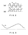
- a solid line represents a voltage V s of the AC power source 6, and a broken line represents a current I m of the induction motor 4.
- a current I m of the induction motor 4 As shown in Fig. 2(b), no current flows through the light emitting diode 15 during a positive half cycle of the voltage of the AC power source 6 so that the light emitting diode 15 does not illuminate. Therefore, the phototransistor 16 is maintained off, and the capacitor 19 is charged through the resistor 18 as indicated by a capacitor voltage V c . At the zero cross point at which a current transits from negative to positive, a pulse signal is output from the differential circuit 23.
- the pulse signal as a sampling control signal is supplied to the sample/hold circuit 20 which in turn samples the input capacitor voltage V c and holds it as a sample/hold voltage V h .
- the sample/hold voltage V h can be expressed in terms of a function of a phase difference between the voltage V c and current I m , and is used as a signal representative of the phase difference in this embodiment.
- As the voltage V s becomes negative current flows through the light emitting diode 15 and causes it to illuminate. Upon reception of this light, the phototransistor 16 is turned on to therefore discharge the capacitor 19 and make its charge voltage zero. The above operations are repeated for each cycle of the power source voltage V s .
- a sample/hold voltage V h as shown in Fig. 3 can be obtained, the sample/hold voltage V h having a cyclical period corresponding to 1/S of the frequency of the AC power source 6, where S represents a slip of the induction motor 4.
- S represents a slip of the induction motor 4.
- the sample/hold voltage V h has a period corresponding to 20 cycles of the AC power source 6 voltage.
- the value of the sample/hold voltage V h at a particular phase is used as a pointer for indicating the shaft position of the induction motor 2 and hence compressor 4.
- the sample/hold voltage V h obtained from the sample/hold circuit 20 is input to the first input terminal of a second comparator 26, the maximum value V x of the sample/hold voltage is held at a maximum value holding circuit 27, and the minimum value V n is held at a minimum value holding circuit 28.
- a comparator reference voltage V a of the comparator 26 which is applied to the second input terminal thereof is obtained by a divider composed of resistors 29 and 30, the comparator reference voltage being set at a middle value between the maximum value V h and minimum value V n and corresponding to the stop position of the compressor.
- the comparator 26 compares the sample/hold voltage V h input to the first input terminal with the comparator reference voltage V a and delivers an output signal S a as a phase signal.
- the output signal S a takes an "H (high level)" signal in the region of V H ⁇ V a and an "L (low level)" signal in the region of V h ⁇ V a .
- the output signal S a from the comparator 26 is input as a clock signl to the C input terminal of a D-type flip-flop (FF) 31, to the D input terminal of which a compressor on/off command S o is input.
- the delay time of the delay circuit 32 is set at a time T D longer than a half cycle and shorter than one cycle (of the power source voltage).
- a compressor-off control signal S c is output from the OR circuit 33 so that the TRIAC 8 is controlled via the photocoupler 10.
- the comparator 26 compares the sample/hold voltage V h from the sample/hold circuit 20 with the comparator reference voltage V a , and delivers an output signal S a which takes an "H” signal in the region of V h ⁇ V a and an "L” signal in the region of V h ⁇ V a .
- the output signal S a is input to the C input terminal of the D-type flip-flop 31. If the compressor on/off command S o input to the D input terminal is an "H" signal at the rising time when the output signal S a changes from "L” to "H” (refer to the points indicated by arrow), the induction motor 4 and hence compressor 2 continues to operate.
- the D-type flip-flop 31 does not change its output.
- the output of the D-type flip-flop 31 changed to "L” at the rising time when the output signal S a of the comparator 26 changes from “L” to "H” after the compressor on/off command S o became “L”.
- the compressor on/off control signal S c output from the OR gate 33 becomes "L”.
- the trigger signal to the TRIAC 8 is intercepted so that no current flows after the following current zero cross point. Namely, the current can be stopped at the current zero cross point.
- the current zero cross point corresponds to the rotary position of the motor 4 and shaft position of the compressor 2 at which vibrations become minimum, thus enabling the compressor 2 to stop with minimum vibration.
- the vibration acceleration became minimum at the minimum point of the phase difference.
- the minimum vibration acceleration was about half the maximum value. According to the present invention, the compressor can always be stopped at the minimum vibration point, thus realizing an air conditioner with substantially small vibration.
- a TRIAC has been used as a switching element for turning on and off the power source for the induction motor 4. Since the current presently passing through a TRIAC cannot be stopped at once at that time unless a forced quenching means is provided, the above embodiment TRIAC is caused to be turned off at the current zero cross point by providing a delay time equal to or shorter than one cycle. If an element whose turning-on/off can be controlled, is used instead of the TRIAC, the current can be stopped immediately at higher precision without providing the delay circuit 32 for waiting for a maximum of one cycle.
- a phase difference between a voltage zero cross point and a current zero cross point of the AC power source is detected to output a signal which turns off the switching means at the current zero cross point.
- turning off the switching means is delayed at a maximum of one cycle so that if the slip of the induction motor is not constant, there may be a displacement, although very small, of the shaft position when the compressor is stopped.
- a power source voltage V s is applied to a zero cross detecting circuit 41, and an output of a current detector 21 is applied to a signal converting circuit 42.
- the zero cross detecting circuit 41 detects a zero cross point of the power source voltage V s and outputs a corresponding zero cross signal V o .
- the signal converting circuit 42 converts a current I m into a corresponding voltage signal V i and outputs it.
- the voltage signal V i hand zero cross signal V o are supplied to a sample/hold circuit 43.
- the sample/hold circuit 43 samples the amplitude of the voltage signal V i (corresponding to the current value I m ) supplied from the signal converting circuit 42 when the AC power source voltage V s changes from negative to positive, in accordance with the zero cross signal V o , and holds it as a sample/hold signal V h (refer to Fig. 6).
- the sample/hold signal V h changes at each cycle of the power source voltage V s to thus have a waveform as shown in Fig. 7(a).
- Fig. 7(b) shows a phase difference between the voltage zero cross point at which the current value is sampled and the current zero cross point.
- a sample generator 40 is constituted by the zero cross detecting circuit 41, signal converting circuit 42 and sample/hold circuit 43.
- the sample/hold signal V h generated at the sample/hold circuit 43 is supplied to a maximum value holding circuit 45 and a minimum value holding circuit 46, and also supplied to the first input terminal of a comparator 48 to be described later.
- the maximum and minimum value holding circuits 45 and 46 hold the maximum value V x and minimum value V n of the input sample/hold signal V h , and output them to the corresponding input terminals of a voltage divider 47.
- the maximum value holding circuit 45 detects the maximum value corresponding to a maximum torque at the time of the voltage zero cross point, and the minimum value holding circuit 46 detects a minimum value corresponding to a minimum torque.
- the voltage divider 47 is constructed of resistors (refer to Fig.
- the comparator reference voltage V a is supplied to the second input terminal of the comparator 48 which compares the sample/hold signal V h with the comparator reference voltage signal V a and outputs a position indicating signal S a .
- the position indicating signal S a takes an "H” signal when the sample/hold signal V h is equal to or larger than the comparator reference voltage signal V a (V h ⁇ V a ) and an "L” signal when the former is smaller their the latter (V h ⁇ V a ).
- the position indicating signal S a is a signal corresponding to a current value detected at the voltage zero cross point.
- the time when the position indicating signal S a is obtained corresponds to the time at and from which the current value gradually increases. It can be judged that the load torque of the induction motor 4 is maximum at such a time, and that the shaft position of the compressor is at a maximum torque position immediately before discharge of the compressor.
- a signal generator 44 is constituted by the maximum value holding circuit 45, minimum value holding circuit 46, divider 47, and comparator 48.
- the position indicating signal S a is supplied to an edge detecting circuit 49 which detects the front or back edge of the rectangular position indicating signal S a upon reception of a compressor on/off command S o , and outputs at the timing of the front or back edge an off-control signal S c for turning off the induction motor 4.
- a compressor on/off command S o of "L" is a stop command signal for turning off the compressor and is output upon the actuation of a thermo-switch for detecting a room temperature or upon actuation of a manual switch.
- the off-control signal S c is applied to a TRIAC 8 serially connected to the induction motor 4.
- the TRIAC 8 and the edge detecting circuit 49 are coupled, for example, by a photocoupler (not shown).
- the off-control signal S c is output from the edge detecting circuit 49 and applied to the TRIAC 8, the TRIAC 8 is turned off so that the induction motor 4 and the compressor connected thereto are stopped.
- the power interception by the TRIAC 8 is carried out on the basis of the voltage zero cross point. Namely, the amplitude of the current I m at the voltage zero cross point of the voltage V s is detected, and the sample/hold circuit 43 outputs a sample/hold signal V h corresponding to the amplitude of the current I m . On the basis of sample/hold signal V h , the position indicating signal S s and off-control signal S c are generated. Thus, power to the induction motor 4 is intercepted at a certain time during from the voltage zero cross point time to the current phase delay time.
Landscapes
- Engineering & Computer Science (AREA)
- Mechanical Engineering (AREA)
- General Engineering & Computer Science (AREA)
- Control Of Ac Motors In General (AREA)
- Control Of Positive-Displacement Pumps (AREA)
Applications Claiming Priority (4)
| Application Number | Priority Date | Filing Date | Title |
|---|---|---|---|
| JP63186368A JPH0237190A (ja) | 1988-07-26 | 1988-07-26 | 空調機におけるコンプレッサのシャフト位置検出方法及び装置並びにそれを用いた空調機の停止制御装置 |
| JP186368/88 | 1988-07-26 | ||
| JP63268694A JPH02114875A (ja) | 1988-10-25 | 1988-10-25 | 空気調和機の制御装置 |
| JP268694/88 | 1988-10-25 |
Publications (3)
| Publication Number | Publication Date |
|---|---|
| EP0353520A2 true EP0353520A2 (fr) | 1990-02-07 |
| EP0353520A3 EP0353520A3 (fr) | 1991-10-23 |
| EP0353520B1 EP0353520B1 (fr) | 1994-09-14 |
Family
ID=26503719
Family Applications (1)
| Application Number | Title | Priority Date | Filing Date |
|---|---|---|---|
| EP89112872A Expired - Lifetime EP0353520B1 (fr) | 1988-07-26 | 1989-07-13 | Méthode et appareil pour détecter la position d'arbre d'un compresseur pour un appareil de conditionnement d'air et appareil de commande pour arrêter le compresseur par mise en service d'appareil de détection de la position d'arbre |
Country Status (3)
| Country | Link |
|---|---|
| US (1) | US5015153A (fr) |
| EP (1) | EP0353520B1 (fr) |
| DE (1) | DE68918198T2 (fr) |
Cited By (3)
| Publication number | Priority date | Publication date | Assignee | Title |
|---|---|---|---|---|
| WO2004104419A1 (fr) * | 2003-05-22 | 2004-12-02 | Empresa Brasileira De Compressores S.A. Embraco | Ensemble de capteur, pompe fluidique et refroidisseur |
| CN104806497A (zh) * | 2014-01-23 | 2015-07-29 | 珠海格力电器股份有限公司 | 压缩机的控制方法及控制装置 |
| CN105090001A (zh) * | 2015-07-20 | 2015-11-25 | 北京化工大学 | 一种基于相似性分析的往复压缩机信号整周期相位校准方法 |
Families Citing this family (11)
| Publication number | Priority date | Publication date | Assignee | Title |
|---|---|---|---|---|
| US5241251A (en) * | 1990-05-21 | 1993-08-31 | Asahi Kogaku Kogyo Kabushiki Kaisha | Drive signal generating device |
| JPH0433584A (ja) * | 1990-05-30 | 1992-02-04 | Toshiba Corp | すべり検出装置およびこれを用いた圧縮機の制御装置 |
| US6174136B1 (en) | 1998-10-13 | 2001-01-16 | Liquid Metronics Incorporated | Pump control and method of operating same |
| US6280147B1 (en) | 1998-10-13 | 2001-08-28 | Liquid Metronics Incorporated | Apparatus for adjusting the stroke length of a pump element |
| US6264432B1 (en) | 1999-09-01 | 2001-07-24 | Liquid Metronics Incorporated | Method and apparatus for controlling a pump |
| KR100378815B1 (ko) * | 2000-11-28 | 2003-04-07 | 엘지전자 주식회사 | 리니어 컴프레샤의 스트로크 떨림 검출장치 및 방법 |
| US20040184791A1 (en) * | 2003-03-21 | 2004-09-23 | Sunbeam Products, Inc. | Closed loop feedback method for electric motor |
| CN104061145A (zh) * | 2014-06-16 | 2014-09-24 | 邯郸美的制冷设备有限公司 | 变频压缩机的控制方法、装置及变频除湿机和变频窗机 |
| WO2016115324A1 (fr) * | 2015-01-15 | 2016-07-21 | Schlumberger Canada Limited | Systèmes et procédés pour le calcul de l'énergie électrique consommée par un moteur à induction |
| CN105715524A (zh) * | 2016-03-09 | 2016-06-29 | 广东美的制冷设备有限公司 | 空调器及其压缩机的停机控制方法和装置 |
| CN114739105B (zh) * | 2022-04-22 | 2024-02-06 | Tcl家用电器(合肥)有限公司 | 变频压缩机的停机控制方法、装置、存储介质及冰箱 |
Family Cites Families (4)
| Publication number | Priority date | Publication date | Assignee | Title |
|---|---|---|---|---|
| US3600657A (en) * | 1970-06-17 | 1971-08-17 | Jeanne Pfaff | Method and apparatus for electronic sensing of motor torque |
| DE3210082A1 (de) * | 1981-04-02 | 1982-10-21 | IWE Ingenieurgesellschaft für wirtschaftliche Energienutzung mbH, 6078 Neu-Isenburg | Verfahren und schaltungsanordnung zur regelung der drehzahl eines pumpenmotors |
| US4481786A (en) * | 1982-06-04 | 1984-11-13 | Whirlpool Corporation | Electronic control for a domestic appliance |
| US4726738A (en) * | 1985-01-16 | 1988-02-23 | Hitachi, Ltd. | Motor-driven compressor provided with torque control device |
-
1989
- 1989-07-13 EP EP89112872A patent/EP0353520B1/fr not_active Expired - Lifetime
- 1989-07-13 DE DE68918198T patent/DE68918198T2/de not_active Expired - Fee Related
- 1989-07-14 US US07/379,650 patent/US5015153A/en not_active Expired - Fee Related
Cited By (6)
| Publication number | Priority date | Publication date | Assignee | Title |
|---|---|---|---|---|
| WO2004104419A1 (fr) * | 2003-05-22 | 2004-12-02 | Empresa Brasileira De Compressores S.A. Embraco | Ensemble de capteur, pompe fluidique et refroidisseur |
| CN100480511C (zh) * | 2003-05-22 | 2009-04-22 | 巴西压缩机股份有限公司 | 传感器组件、流体泵及冷却器 |
| US8342811B2 (en) | 2003-05-22 | 2013-01-01 | Whirlpool S.A. | Sensor assembly, a fluid pump and a cooler |
| CN104806497A (zh) * | 2014-01-23 | 2015-07-29 | 珠海格力电器股份有限公司 | 压缩机的控制方法及控制装置 |
| CN105090001A (zh) * | 2015-07-20 | 2015-11-25 | 北京化工大学 | 一种基于相似性分析的往复压缩机信号整周期相位校准方法 |
| CN105090001B (zh) * | 2015-07-20 | 2017-05-03 | 北京化工大学 | 一种基于相似性分析的往复压缩机信号整周期相位校准方法 |
Also Published As
| Publication number | Publication date |
|---|---|
| DE68918198D1 (de) | 1994-10-20 |
| US5015153A (en) | 1991-05-14 |
| DE68918198T2 (de) | 1995-04-13 |
| EP0353520A3 (fr) | 1991-10-23 |
| EP0353520B1 (fr) | 1994-09-14 |
Similar Documents
| Publication | Publication Date | Title |
|---|---|---|
| US5015153A (en) | Compressor cutoff control responsive to shaft position | |
| US4604563A (en) | Electronic switch for starting AC motor | |
| US5041771A (en) | Motor starting circuit | |
| EP0455237B1 (fr) | Appareil de régulation d'un moteur électrique | |
| US4510429A (en) | Stepper motor damping circuit and a method therefor | |
| US4801858A (en) | Motor starting circuit | |
| US4381481A (en) | Control circuit for a stepping motor in battery-operated instruments | |
| KR950010382B1 (ko) | 전자렌지를 구비한 냉동 · 냉장고 제어회로 | |
| US5859513A (en) | Starting and synchronizing system for line-start permanent magnet motor | |
| US4672284A (en) | Permanent split-phase capacitor induction motor | |
| SK284657B6 (sk) | Spôsob prevádzky jednofázového synchrónneho motora a zariadenie na uskutočňovanie tohto spôsobu | |
| KR930005661B1 (ko) | 공조기의 콤프레서의 샤프트 위치 검출방법 | |
| US4489264A (en) | Power Control for AC motor | |
| US3518434A (en) | X-ray tube rotatable anode control circuit with means to sense and control anode motor current | |
| SU1624649A1 (ru) | Стабилизированный электропривод | |
| US4683413A (en) | Reducing power consumption and monitoring synchronous running of three-phase electric motors | |
| JPS6389084A (ja) | 瞬間的反転回路 | |
| US20090128082A1 (en) | Switching system for controlling the starting of an electrical motor | |
| KR930002896B1 (ko) | 공기조화기의 제어장치 | |
| US4967122A (en) | Digital synchronizing circuit for brushless DC motor | |
| KR20000006036A (ko) | 전기모터의전력공급용회로장치 | |
| US4952860A (en) | Motor control system | |
| US3484669A (en) | Synchronous motor excitation control system | |
| KR0113964Y1 (ko) | 직류모터를 이용한 냉장고용 온도 조절회로 | |
| GB2165408A (en) | A.C. motor control |
Legal Events
| Date | Code | Title | Description |
|---|---|---|---|
| PUAI | Public reference made under article 153(3) epc to a published international application that has entered the european phase |
Free format text: ORIGINAL CODE: 0009012 |
|
| 17P | Request for examination filed |
Effective date: 19890726 |
|
| AK | Designated contracting states |
Kind code of ref document: A2 Designated state(s): DE GB IT |
|
| PUAL | Search report despatched |
Free format text: ORIGINAL CODE: 0009013 |
|
| AK | Designated contracting states |
Kind code of ref document: A3 Designated state(s): DE GB IT |
|
| 17Q | First examination report despatched |
Effective date: 19930511 |
|
| GRAA | (expected) grant |
Free format text: ORIGINAL CODE: 0009210 |
|
| AK | Designated contracting states |
Kind code of ref document: B1 Designated state(s): DE GB IT |
|
| REF | Corresponds to: |
Ref document number: 68918198 Country of ref document: DE Date of ref document: 19941020 |
|
| ITF | It: translation for a ep patent filed | ||
| PLBE | No opposition filed within time limit |
Free format text: ORIGINAL CODE: 0009261 |
|
| STAA | Information on the status of an ep patent application or granted ep patent |
Free format text: STATUS: NO OPPOSITION FILED WITHIN TIME LIMIT |
|
| 26N | No opposition filed | ||
| PGFP | Annual fee paid to national office [announced via postgrant information from national office to epo] |
Ref country code: GB Payment date: 19970704 Year of fee payment: 9 |
|
| PGFP | Annual fee paid to national office [announced via postgrant information from national office to epo] |
Ref country code: DE Payment date: 19970718 Year of fee payment: 9 |
|
| PG25 | Lapsed in a contracting state [announced via postgrant information from national office to epo] |
Ref country code: GB Free format text: LAPSE BECAUSE OF NON-PAYMENT OF DUE FEES Effective date: 19980713 |
|
| GBPC | Gb: european patent ceased through non-payment of renewal fee |
Effective date: 19980713 |
|
| PG25 | Lapsed in a contracting state [announced via postgrant information from national office to epo] |
Ref country code: DE Free format text: LAPSE BECAUSE OF NON-PAYMENT OF DUE FEES Effective date: 19990501 |
|
| PG25 | Lapsed in a contracting state [announced via postgrant information from national office to epo] |
Ref country code: IT Free format text: LAPSE BECAUSE OF NON-PAYMENT OF DUE FEES;WARNING: LAPSES OF ITALIAN PATENTS WITH EFFECTIVE DATE BEFORE 2007 MAY HAVE OCCURRED AT ANY TIME BEFORE 2007. THE CORRECT EFFECTIVE DATE MAY BE DIFFERENT FROM THE ONE RECORDED. Effective date: 20050713 |