EP0353524A2 - Appareil pour éprouver l'étanchéité à l'eau d'objets de revêtement - Google Patents
Appareil pour éprouver l'étanchéité à l'eau d'objets de revêtement Download PDFInfo
- Publication number
- EP0353524A2 EP0353524A2 EP89112978A EP89112978A EP0353524A2 EP 0353524 A2 EP0353524 A2 EP 0353524A2 EP 89112978 A EP89112978 A EP 89112978A EP 89112978 A EP89112978 A EP 89112978A EP 0353524 A2 EP0353524 A2 EP 0353524A2
- Authority
- EP
- European Patent Office
- Prior art keywords
- moisture
- clothing
- shoe
- threshold
- water
- Prior art date
- Legal status (The legal status is an assumption and is not a legal conclusion. Google has not performed a legal analysis and makes no representation as to the accuracy of the status listed.)
- Withdrawn
Links
- 238000012360 testing method Methods 0.000 title claims abstract description 59
- XLYOFNOQVPJJNP-UHFFFAOYSA-N water Substances O XLYOFNOQVPJJNP-UHFFFAOYSA-N 0.000 title claims abstract description 54
- 238000011156 evaluation Methods 0.000 claims abstract description 20
- 230000007246 mechanism Effects 0.000 claims description 9
- 230000035515 penetration Effects 0.000 claims description 7
- 241001669679 Eleotris Species 0.000 claims description 4
- 238000000034 method Methods 0.000 claims description 3
- 230000003287 optical effect Effects 0.000 claims description 2
- 230000008569 process Effects 0.000 claims description 2
- 230000004913 activation Effects 0.000 claims 3
- 230000000284 resting effect Effects 0.000 claims 1
- 210000002683 foot Anatomy 0.000 description 15
- 229910000831 Steel Inorganic materials 0.000 description 11
- 239000010959 steel Substances 0.000 description 11
- 210000003371 toe Anatomy 0.000 description 7
- 239000002346 layers by function Substances 0.000 description 5
- 238000005096 rolling process Methods 0.000 description 5
- 239000004744 fabric Substances 0.000 description 4
- 238000004519 manufacturing process Methods 0.000 description 3
- 230000008859 change Effects 0.000 description 2
- 238000010586 diagram Methods 0.000 description 2
- 238000009826 distribution Methods 0.000 description 2
- 239000000463 material Substances 0.000 description 2
- 239000004753 textile Substances 0.000 description 2
- TUSDEZXZIZRFGC-UHFFFAOYSA-N 1-O-galloyl-3,6-(R)-HHDP-beta-D-glucose Natural products OC1C(O2)COC(=O)C3=CC(O)=C(O)C(O)=C3C3=C(O)C(O)=C(O)C=C3C(=O)OC1C(O)C2OC(=O)C1=CC(O)=C(O)C(O)=C1 TUSDEZXZIZRFGC-UHFFFAOYSA-N 0.000 description 1
- RYGMFSIKBFXOCR-UHFFFAOYSA-N Copper Chemical compound [Cu] RYGMFSIKBFXOCR-UHFFFAOYSA-N 0.000 description 1
- 239000001263 FEMA 3042 Substances 0.000 description 1
- LRBQNJMCXXYXIU-PPKXGCFTSA-N Penta-digallate-beta-D-glucose Natural products OC1=C(O)C(O)=CC(C(=O)OC=2C(=C(O)C=C(C=2)C(=O)OC[C@@H]2[C@H]([C@H](OC(=O)C=3C=C(OC(=O)C=4C=C(O)C(O)=C(O)C=4)C(O)=C(O)C=3)[C@@H](OC(=O)C=3C=C(OC(=O)C=4C=C(O)C(O)=C(O)C=4)C(O)=C(O)C=3)[C@H](OC(=O)C=3C=C(OC(=O)C=4C=C(O)C(O)=C(O)C=4)C(O)=C(O)C=3)O2)OC(=O)C=2C=C(OC(=O)C=3C=C(O)C(O)=C(O)C=3)C(O)=C(O)C=2)O)=C1 LRBQNJMCXXYXIU-PPKXGCFTSA-N 0.000 description 1
- 230000003187 abdominal effect Effects 0.000 description 1
- 230000003213 activating effect Effects 0.000 description 1
- 238000005452 bending Methods 0.000 description 1
- 229910052802 copper Inorganic materials 0.000 description 1
- 239000010949 copper Substances 0.000 description 1
- 238000005516 engineering process Methods 0.000 description 1
- 238000005530 etching Methods 0.000 description 1
- 210000001255 hallux Anatomy 0.000 description 1
- 210000003127 knee Anatomy 0.000 description 1
- 239000000203 mixture Substances 0.000 description 1
- 230000035699 permeability Effects 0.000 description 1
- 238000012545 processing Methods 0.000 description 1
- 238000003672 processing method Methods 0.000 description 1
- 238000011160 research Methods 0.000 description 1
- 230000004044 response Effects 0.000 description 1
- 238000004088 simulation Methods 0.000 description 1
- LRBQNJMCXXYXIU-NRMVVENXSA-N tannic acid Chemical compound OC1=C(O)C(O)=CC(C(=O)OC=2C(=C(O)C=C(C=2)C(=O)OC[C@@H]2[C@H]([C@H](OC(=O)C=3C=C(OC(=O)C=4C=C(O)C(O)=C(O)C=4)C(O)=C(O)C=3)[C@@H](OC(=O)C=3C=C(OC(=O)C=4C=C(O)C(O)=C(O)C=4)C(O)=C(O)C=3)[C@@H](OC(=O)C=3C=C(OC(=O)C=4C=C(O)C(O)=C(O)C=4)C(O)=C(O)C=3)O2)OC(=O)C=2C=C(OC(=O)C=3C=C(O)C(O)=C(O)C=3)C(O)=C(O)C=2)O)=C1 LRBQNJMCXXYXIU-NRMVVENXSA-N 0.000 description 1
- 229940033123 tannic acid Drugs 0.000 description 1
- 235000015523 tannic acid Nutrition 0.000 description 1
- 229920002258 tannic acid Polymers 0.000 description 1
- 210000000689 upper leg Anatomy 0.000 description 1
Images


Classifications
-
- G—PHYSICS
- G01—MEASURING; TESTING
- G01N—INVESTIGATING OR ANALYSING MATERIALS BY DETERMINING THEIR CHEMICAL OR PHYSICAL PROPERTIES
- G01N15/00—Investigating characteristics of particles; Investigating permeability, pore-volume or surface-area of porous materials
- G01N15/08—Investigating permeability, pore-volume, or surface area of porous materials
-
- G—PHYSICS
- G01—MEASURING; TESTING
- G01M—TESTING STATIC OR DYNAMIC BALANCE OF MACHINES OR STRUCTURES; TESTING OF STRUCTURES OR APPARATUS, NOT OTHERWISE PROVIDED FOR
- G01M3/00—Investigating fluid-tightness of structures
- G01M3/02—Investigating fluid-tightness of structures by using fluid or vacuum
- G01M3/04—Investigating fluid-tightness of structures by using fluid or vacuum by detecting the presence of fluid at the leakage point
- G01M3/16—Investigating fluid-tightness of structures by using fluid or vacuum by detecting the presence of fluid at the leakage point using electric detection means
-
- G—PHYSICS
- G01—MEASURING; TESTING
- G01N—INVESTIGATING OR ANALYSING MATERIALS BY DETERMINING THEIR CHEMICAL OR PHYSICAL PROPERTIES
- G01N33/00—Investigating or analysing materials by specific methods not covered by groups G01N1/00 - G01N31/00
- G01N33/36—Textiles
- G01N33/367—Fabric or woven textiles
-
- G—PHYSICS
- G01—MEASURING; TESTING
- G01N—INVESTIGATING OR ANALYSING MATERIALS BY DETERMINING THEIR CHEMICAL OR PHYSICAL PROPERTIES
- G01N15/00—Investigating characteristics of particles; Investigating permeability, pore-volume or surface-area of porous materials
- G01N15/08—Investigating permeability, pore-volume, or surface area of porous materials
- G01N2015/0853—Investigating permeability, pore-volume, or surface area of porous materials by electrical capacitance measurement
-
- G—PHYSICS
- G01—MEASURING; TESTING
- G01N—INVESTIGATING OR ANALYSING MATERIALS BY DETERMINING THEIR CHEMICAL OR PHYSICAL PROPERTIES
- G01N33/00—Investigating or analysing materials by specific methods not covered by groups G01N1/00 - G01N31/00
- G01N33/36—Textiles
-
- G—PHYSICS
- G01—MEASURING; TESTING
- G01N—INVESTIGATING OR ANALYSING MATERIALS BY DETERMINING THEIR CHEMICAL OR PHYSICAL PROPERTIES
- G01N33/00—Investigating or analysing materials by specific methods not covered by groups G01N1/00 - G01N31/00
- G01N33/44—Resins; Plastics; Rubber; Leather
Definitions
- the invention relates to a device for testing items of clothing for water resistance, with a carrier device, to which the item of clothing to be tested can be pulled over, the item of clothing being pulled over the carrier device in the dry state being acted upon with water and examined for moisture on the inside and the surface of the Carrier device is provided at least at points of the clothing article which are particularly critical for the penetration of water with moisture sensors which are connected to an evaluation device.
- the so-called PFI tester from the testing and research institute of the shoe industry has been used to test shoes for water resistance.
- This comprises a steel bar, which is formed like a bar only in the toe area, otherwise has the shape of a narrow bar.
- this steel last is designed with a spring-loaded joint. This allows the strip-like tip to be raised against the spring force and allowed to return to its rest position.
- the shoe to be tested which is pulled over the steel lasts, is placed with its heel on a fixed steel plate and with its toe area on a movable steel plate. This steel plate is brought into motion that has a horizontal component and a vertical component. This requires a complex mechanism which is immersed in the water bath, which is particularly aggressive because of the tannic acid leaking from the shoes to be tested and which attacks and permanently damages the mechanism.
- the known steel last which has the shape of a narrow steel ledge or steel rod except for the tip, has contact with the shoe to be tested only in two places of relatively small area. Due to the pressure from the base plate, this steel bar moves in the shoe. At the points of contact between the steel last and the shoe, the lining can be chafed or chafed and thus the waterproof functional layer. If moisture is then found in the shoe, it is often not possible to clearly distinguish whether it has penetrated due to a frayed functional layer or due to any system or production-related water bridges.
- the water leak test was carried out by inspecting and feeling the shoe removed from the last. Often, blotting paper or the like has been inserted into the removed shoe in order to be able to determine any moisture that has entered. On the one hand, this method is imprecise and, on the other hand, does not allow an exact statement as to how many movement cycles the moisture has occurred. Because it depends purely on coincidence after how many movement cycles the operator stops the shoe tester, takes the shoe out of the water and examines the inside of the shoe for moisture.
- the well-known shoe tester is only designed for testing a very specific shoe size. If a shorter last for a smaller shoe were to be attached to the holding device for the shoe last, the base plate which could be moved up and down would no longer be in the correct place under the toe region of the smaller shoe. Ent Conversely, the reverse applies to a larger shoe than that intended for the shoe tester.
- the invention has for its object to provide a device for testing items of clothing for water resistance, with which items of clothing can be tested with high accuracy, reliability and reliability in a situation that comes as close as possible to actual use.
- the solution of this invention consists in a device for testing items of clothing for water resistance, with a carrier device to which the item of clothing to be tested can be put on, the item of clothing being pulled over the carrier device in the dry state being exposed to water and examined for moisture on the inside and the surface of the carrier device is provided at least at points of the clothing item which are particularly critical for the penetration of water with moisture sensors which are connected to an evaluation device, characterized in that the carrier device in is essentially modeled on a human body or body part and that the evaluation device feeds a display device which indicates the contour of the body part to be dressed with the article of clothing and has optical display elements at the locations corresponding to the sensor positions, which are brought into a display state by the evaluation device when the Associated moisture sensor reports moisture.
- JP-A2 58-10651 it is known to measure the heat resistance of articles of clothing by covering them with a human doll provided with heat sensors and then directing heat sources onto the doll.
- the surface of the carrier device which can be, for example, a shoe last, a glove last or a body doll, is provided with moisture sensors at various points
- the water resistance test can be carried out without the article of clothing being removed again and again by the carrier device must be removed to check whether moisture has already penetrated to the inside. Because the evaluation is automatic expires while the article of clothing is pulled over the carrier device, the exact point in time at which moisture has penetrated into the interior can be determined and recorded. Since the criterion dry or moist is decided based on the output signals of the moisture sensors, the water resistance test can be stopped automatically as soon as a moisture sensor reports moisture without an operator being present.
- the test device can be left entirely to its own devices.
- a test device with a plurality of carrier devices is used in a preferred manner, for example a shoe tester with several foot simulations or prosthetic feet, which are each measured and evaluated separately from one another, the test device can be left to run for hours or even days and takes time after this time only read the test results for the individual items of clothing. If you consider that, for example, waterproof shoes in a shoe tester are subjected to a number of movement cycles which are in the range of a few hundred or even millions until the end of the test, one can imagine how great the labor saving is.
- test device In the case of items of clothing such as jackets, coats and trousers, it would of course be very complex to check all areas of the item of clothing which experience has shown to be particularly critical for the penetration of moisture using the known water column test. Locations that had previously been recognized as non-critical and that may only prove to be critical with a specific production method would remain unchecked in the known water column test. If, on the other hand, the test device according to the invention is used in the form of a human puppet provided with moisture sensors, any number of moisture sensors can be attached at any point on the doll, so that a jacket or coat can be applied to the penetration of any number of points in a single test process Have moisture examined.
- the doll or parts thereof can be made inflatable in order to ensure that the moisture sensors on the inside of the item of clothing to be tested are particularly well attached.
- the doll with the item of clothing to be tested is placed in a shower cubicle which has a large number of shower heads located at different positions, so that the item of clothing can be subjected to water from practically all sides at the same time.
- the test device is particularly clear and easy to use, since it is assigned a display device which indicates the shape of the item of clothing to be tested and preferably with lighting elements Light-emitting diodes are provided at locations that correspond to the positions of the individual moisture sensors on the carrier device. Then you can see at a glance where the item of clothing to be tested is leaking.
- an embodiment of a shoe tester is considered first.
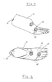
- a foot replica in the form of a prosthetic foot 11 is used, which consists of elastically flexible material at least in the front area. This makes it possible for the patient to be drawn on the prosthetic foot 11. Perform a rolling movement that can largely correspond to the rolling movement of a natural foot when walking.
- Moisture sensors 13 are arranged at various points on the surface of the prosthetic foot 11 and can be connected to an electrical evaluation device by means of electrical lines 15.
- the individual moisture sensors 13 are mainly arranged at those places where a shoe is normally exposed to particular pressure or bending stress, such as in the flex area above the toe attachments, in the heel area and at various places Make the sole of the foot.
- a moisture sensor is also attached under the free end of the big toe, since the corresponding area of the shoe is exposed to relatively heavy loads when walking.
- at least one moisture sensor 13 is located in the area of the shoe tongue in order to be able to determine whether this area, which is sensitive to water ingress, remains dry.
- the test device essentially consists of a holding device for the shoe to be tested, a drive unit for the walking movement, a water tub and an electronic control with display device.
- the mechanical part of the test device is now explained in more detail with reference to FIG. 3.
- a water pan 19 and a guide 21 which is adjustable in the vertical direction relative to the frame 17 are arranged on a frame 17.
- a screw lever 22 is loosened and screwed again after the new vertical position of the guide 21 has been set.
- a bracket 25 for a pneumatic cylinder 27 is attached to the guide 21.
- a holding rod 29 is movably arranged in the pneumatic cylinder 27, at the free end of which a holding device 31 is arranged, at the other end of which the prosthetic foot 11, which is not visible in FIG. 3, is attached.
- a shoe 33 which has a sole 35 and a shoulder 37, is pulled onto the prosthetic foot 11 to be checked for water resistance.
- the paragraph 37 is on a footprint 39 which is connected to the guide 21.
- the toe region of the sole 35 lies on a threshold 41, which can be moved up and down in an arcuate movement, in order for the front region of the shoe 33 Simulate rolling motion when walking naturally.
- the movement mechanism of the threshold 41 can be seen more clearly from FIG. 4.
- This movement mechanism comprises a lever 43 which is raised and lowered by an adjustable speed motor by means of a crank mechanism.
- the threshold 41 is rotatably attached to the lower end of the lever 43 by means of a horizontally extending rotary shaft 45.
- the gear 47 meshes with a gear segment 49 which is fastened to the bottom of the frame 17 by means of screws 51.
- the threshold 41 is rotated together with the gear 47 about the rotary shaft 45 simultaneously with the raising and lowering.
- the threshold therefore makes an arcuate up and down movement.
- the shoe 43 located on the threshold 41 performs a realistic rolling process as in natural running.
- a long sleeper 41 By arranging a crank mechanism, a lever 43, a gear 47 and a gear segment 49 at each of the two longitudinal ends of the sleeper 41, a long sleeper 41 can be realized, on which a large number of shoes can be placed side by side.
- the moisture sensors 13 of each foot prosthesis are detachably connected via an electrical plug connection and a flat cable to an evaluation device with one display unit each. Because the guides 21 are adjustable in height, each test unit can be adjusted according to the heel height of the shoe 33 or boot to be tested with this test unit such that the front region of the sole 35 always lies in a suitable manner on the threshold 41.
- each guide 21 (in a manner not shown) is adjustable in the longitudinal direction of the shoe. This makes it possible to adjust the test device to any shoe length in such a way that the part of the sole 35 located in the toe area always lies in a suitable manner on the threshold 41.
- each guide 21 is individually adjustable in height.
- each footprint 39 is individually adjustable in the longitudinal direction of the shoe.
- Each test unit assigned to a shoe 33 can be individually lowered and raised by means of its pneumatic unit 27, 29.
- Each test unit is assigned its own display device and its own movement cycle counter. As soon as a moisture sensor 13 reports moisture in a test unit, the shoe 33 concerned is lifted out of the water bath by lifting the associated support rod 29 by means of the pneumatic cylinder 27, it being possible to see from the display device which of the moisture sensors of this test unit reports moisture and at which count the Movement cycle counter the moisture message has occurred.
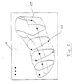
- each display device has a schematic representation 53 of a prosthetic foot, with light-emitting diodes 55 being arranged at the locations corresponding to the moisture sensors. As soon as a moisture sensor 13 reports moisture, the associated light-emitting diode 55 lights up. It can therefore be determined at a glance at which point the tested shoe 33 has let water through.
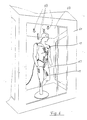
- FIGS. 6 to 9 A preferred embodiment of a test device for articles of clothing such as jackets, pants, coats or overalls is shown in FIGS. 6 to 9.
- a manikin 63 of human shape and size, on the surface of which a large number of moisture sensors 13 are arranged. These are mainly located at locations that are particularly critical for the ingress of water. These are the shoulder areas, the abdominal area, where there are often problematic zippers with regard to water resistance, the crotch area, the thigh and knee area and the shin area.
- On the ceiling 67 of the shower cubicle 61 there are a plurality of shower heads 69 which are located at different points with respect to the doll 63 and can have different water-jet directions.
- FIG. 7 shows a top view of the doll 63 from above.
- FIG. 8 shows a rear view of the doll 63 with those places where moisture sensors are preferably located 13 are located.
- 9 shows a side view of the doll with a preferred position for moisture sensors 13 mounted in the rear shoulder area.
- the doll is at least partially inflatable. It is thereby achieved that the moisture sensors 65 located in the inflatable area are certainly brought to bear against the inside of the item of clothing to be tested.
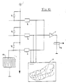
- FIG. 10 A simplified electrical block diagram for an evaluation circuit connected to a plurality of moisture sensors is shown in FIG. 10. This shows in a simplified manner only connections for three moisture sensors 13, although the carrier device of a test device according to the invention will usually have more sensors. Only the lower sensor 13 is shown, while the connecting lines are only shown in dashed lines for the two upper sensors.
- the moisture sensors 13 are connected on the one hand via an associated series resistor R to a common voltage source V and on the other hand each to a ground connection.
- the connection points between the individual series resistors and the associated moisture sensors are each connected to a threshold circuit S, the outputs of which are connected together to a relay driver T, the output of which controls a relay RE.
- the moisture sensor 13 has a multiplicity of interdigitated electrodes, adjacent electrodes being attached to different poles of the voltage supply source are closed. In the completely dry state, no current flows between the oppositely polarized electrodes. If moisture comes into contact with a moisture sensor 13 through the item of clothing to be tested, the electrical conductivity that water of normal composition leads to leads to electrical conduction between the opposing electrodes and thus to a current flow through the associated series resistor R. This in turn leads to a Change in the electrical potential at the input of the associated threshold circuit S. If the current flow through the moisture sensor 13 and thus the potential change at the input of the threshold circuit S exceeds a certain threshold, the output signal of the threshold switch S via the driver amplifier T causes the relay RE to respond.
- the moisture sensors 13 preferably consist of two parallel and self-branching copper electrodes, which are produced using etching technology. Such moisture sensors suffer when current flows through them when wet. Therefore, in a preferred embodiment, the current flow through the moisture sensors 13 is also interrupted by the response of the relay RE. So that it can also be subsequently determined on the display device A which of the moisture sensors 13 has addressed, the display pattern of the display device A is also held by the relay RA. This display and the count of the movement cycle counter can then be held and displayed for any length of time, for example until the start of a new test.
- the exit of shower water is preferably stopped by activating the relay RE.
- the display on the display device A and the test time determined by the test time measuring device are recorded and displayed until these displays are no longer desired, for example because a new test is started.
Landscapes
- Chemical & Material Sciences (AREA)
- General Physics & Mathematics (AREA)
- Engineering & Computer Science (AREA)
- Physics & Mathematics (AREA)
- Health & Medical Sciences (AREA)
- Life Sciences & Earth Sciences (AREA)
- Pathology (AREA)
- Textile Engineering (AREA)
- Biochemistry (AREA)
- Immunology (AREA)
- Analytical Chemistry (AREA)
- General Health & Medical Sciences (AREA)
- Food Science & Technology (AREA)
- Dispersion Chemistry (AREA)
- Medicinal Chemistry (AREA)
- Footwear And Its Accessory, Manufacturing Method And Apparatuses (AREA)
- Investigating Or Analyzing Materials By The Use Of Electric Means (AREA)
- Testing Or Calibration Of Command Recording Devices (AREA)
- Treatment Of Fiber Materials (AREA)
- Measurement Of The Respiration, Hearing Ability, Form, And Blood Characteristics Of Living Organisms (AREA)
Applications Claiming Priority (2)
| Application Number | Priority Date | Filing Date | Title |
|---|---|---|---|
| DE3826275 | 1988-06-13 | ||
| DE3826275A DE3826275A1 (de) | 1988-08-02 | 1988-08-02 | Vorrichtung zum testen von bekleidungsgegenstaenden auf wasserdichtigkeit |
Publications (2)
| Publication Number | Publication Date |
|---|---|
| EP0353524A2 true EP0353524A2 (fr) | 1990-02-07 |
| EP0353524A3 EP0353524A3 (fr) | 1990-05-16 |
Family
ID=6360109
Family Applications (1)
| Application Number | Title | Priority Date | Filing Date |
|---|---|---|---|
| EP89112978A Withdrawn EP0353524A3 (fr) | 1988-08-02 | 1989-07-14 | Appareil pour éprouver l'étanchéité à l'eau d'objets de revêtement |
Country Status (7)
| Country | Link |
|---|---|
| US (1) | US4961339A (fr) |
| EP (1) | EP0353524A3 (fr) |
| JP (1) | JPH0288943A (fr) |
| AU (1) | AU3586189A (fr) |
| CA (1) | CA1335629C (fr) |
| DE (1) | DE3826275A1 (fr) |
| PT (1) | PT91329A (fr) |
Cited By (4)
| Publication number | Priority date | Publication date | Assignee | Title |
|---|---|---|---|---|
| EP0837329A1 (fr) * | 1996-10-15 | 1998-04-22 | W.L. GORE & ASSOCIATES GmbH | Corps d'essai pour vêtements |
| EP2154505A2 (fr) | 2008-07-29 | 2010-02-17 | POLO EXPRESSVERSAND Gesellschaft für Motorradbekleidung und Sportswear mbH | Cabine de pluie |
| EP1744152B1 (fr) * | 2005-06-24 | 2014-04-23 | Electrolux Home Products Corporation N.V. | Méthode d'utilisation d'un séchoir avec un capteur d'humidité |
| CN120467994A (zh) * | 2025-05-30 | 2025-08-12 | 浙江成如旦涂层材料有限公司 | 一种环保水性涂层布制造用测试装置及测试方法 |
Families Citing this family (22)
| Publication number | Priority date | Publication date | Assignee | Title |
|---|---|---|---|---|
| US5114425A (en) * | 1990-05-25 | 1992-05-19 | Novatec Medical Products, Inc. | Method and apparatus for detecting actual or likely adulteration of critical use gloves |
| US5658277A (en) * | 1990-05-25 | 1997-08-19 | Novatec Medical Products, Inc. | Apparatus for electrical connection of glove monitor to patient |
| US5633453A (en) * | 1993-01-19 | 1997-05-27 | Mayo Foundation For Medical Education And Research | Universal penetration test apparatus and method |
| US5866801A (en) * | 1993-01-19 | 1999-02-02 | Regents Of The University Of California | Universal penetration test apparatus with fluid penetration sensor |
| US5467639A (en) * | 1993-01-19 | 1995-11-21 | Mayo Foundation For Medical Education And Research | Universal penetration test apparatus and method |
| US5329807A (en) * | 1993-06-18 | 1994-07-19 | W. L. Gore & Associates, Inc. | Centrifuge test apparatus for footwear and apparel |
| IT1307159B1 (it) * | 1999-01-14 | 2001-10-29 | Nottington Holding Bv | Apparecchiatura per la misurazione della capacita' di traspirazione diuna calzatura. |
| ITPD20020186A1 (it) * | 2002-07-09 | 2004-01-09 | Geox Spa | Apparecchiatura perfezionata per la misurazione della capacita' di traspirazione e del comfort di una calzatura |
| ITMI20032145A1 (it) * | 2003-11-07 | 2005-05-08 | Nextec Srl | Metodo ed apparecchio per prove di impermeabilizzazione |
| JP4932568B2 (ja) * | 2007-03-30 | 2012-05-16 | サンダイヤポリマー株式会社 | 水分測定装置 |
| CN102034335A (zh) * | 2009-09-24 | 2011-04-27 | 鸿富锦精密工业(深圳)有限公司 | 水域救生监控装置 |
| CN102034336A (zh) * | 2009-09-29 | 2011-04-27 | 鸿富锦精密工业(深圳)有限公司 | 水域救生监控装置及方法 |
| KR101185825B1 (ko) | 2011-06-17 | 2012-10-02 | 한국생산기술연구원 | 의류의 방수 성능 시험 장치 |
| DE102012006243B4 (de) * | 2012-03-28 | 2014-11-06 | Fraunhofer-Gesellschaft zur Förderung der angewandten Forschung e.V. | Versuchspuppe und Teststand zur Dekontaminationsuntersuchung |
| US9086351B1 (en) * | 2013-03-14 | 2015-07-21 | The United States Of America As Represented By The Secretary Of The Army | Fixture for system-level glove testing of contact permeation |
| CN107153080B (zh) * | 2017-07-03 | 2023-07-21 | 四川省皮革研究所 | 一种成鞋热阻、湿阻的测试装置以及测试方法 |
| CN108152173A (zh) * | 2017-12-21 | 2018-06-12 | 浙江华电器材检测研究所有限公司 | 一种安全帽吸湿导汗性能测试的装置 |
| CN110987648A (zh) * | 2019-12-10 | 2020-04-10 | 浙江今日蓝纤科技有限公司 | 一种衣帽生产用成品质量检测装置 |
| CN111122411A (zh) * | 2019-12-31 | 2020-05-08 | 江西服装学院 | 一种面料防水性检测装置 |
| CN114659719B (zh) * | 2022-03-17 | 2023-12-08 | 芜湖风雪橡胶有限公司 | 一种胶鞋制品漏水检测方法、系统 |
| DE102022001863B3 (de) | 2022-05-27 | 2023-04-27 | Bundesrepublik Deutschland (Bundesamt für Ausrüstung, Informationstechnik und Nutzung der Bundeswehr) | Partikelmessvorrichtung |
| CN116793590B (zh) * | 2023-08-21 | 2023-11-17 | 豫北凯斯特隆(新乡)汽车科技有限公司 | 一种泥水喷淋试验平台及其试验方法 |
Family Cites Families (14)
| Publication number | Priority date | Publication date | Assignee | Title |
|---|---|---|---|---|
| US2012762A (en) * | 1932-08-13 | 1935-08-27 | Firm Chem Fab R Baumheier Ag | Method of and system for testing the imperviousness to water of impregnated textiles |
| US2547367A (en) * | 1946-03-13 | 1951-04-03 | Henry Booth Methods Corp | Method and apparatus for testing fabrics |
| US2839644A (en) * | 1948-11-03 | 1958-06-17 | American Instr Company | Apparatus for determining humidity conditions in materials |
| DE1829835U (de) * | 1960-08-31 | 1961-04-20 | Friedrich Bundschuh | Pruef-, sortier- und rollmaschine. |
| FR1339712A (fr) * | 1961-09-28 | 1963-10-11 | Benckiser Gmbh Joh A | Procédé et dispositif de mesure de la capacité d'absorption et de la remouillabilité des matériaux textiles |
| JPS503138A (fr) * | 1973-05-12 | 1975-01-14 | ||
| US3886791A (en) * | 1973-07-23 | 1975-06-03 | Panel Company Q | Cyclic test apparatus |
| US4194041A (en) * | 1978-06-29 | 1980-03-18 | W. L. Gore & Associates, Inc. | Waterproof laminate |
| DD138825B1 (de) * | 1978-09-18 | 1982-11-24 | Hofmann Hans Peter | Simulator zur bestimmung des waermerueckhaltevermoegens von bekleidung |
| JPS5810651A (ja) * | 1981-07-13 | 1983-01-21 | Yoshikatsu Kawashima | 衣服の防熱性試験機 |
| US4432223A (en) * | 1982-08-06 | 1984-02-21 | The United States Of America As Represented By The Secretary Of The Army | Footwear testing apparatus and method |
| FR2534050A1 (fr) * | 1982-10-05 | 1984-04-06 | Meca Appliquees Lab | Elements de mannequin chauffant pour evaluation thermique, notamment pour etudier les proprietes thermiques d'un vetement et les consequences thermiques dues au port d'un systeme respiratoire |
| US4655235A (en) * | 1984-10-18 | 1987-04-07 | Scott Jr Ralph A | Chemical contamination monitor |
| JPS62277544A (ja) * | 1986-05-27 | 1987-12-02 | Asahi Chem Ind Co Ltd | 衣服の機能評価装置 |
-
1988
- 1988-08-02 DE DE3826275A patent/DE3826275A1/de active Granted
-
1989
- 1989-05-31 AU AU35861/89A patent/AU3586189A/en not_active Abandoned
- 1989-06-12 JP JP1146903A patent/JPH0288943A/ja active Pending
- 1989-06-12 US US07/365,150 patent/US4961339A/en not_active Expired - Fee Related
- 1989-06-12 CA CA000602455A patent/CA1335629C/fr not_active Expired - Lifetime
- 1989-07-14 EP EP89112978A patent/EP0353524A3/fr not_active Withdrawn
- 1989-07-31 PT PT91329A patent/PT91329A/pt not_active Application Discontinuation
Cited By (6)
| Publication number | Priority date | Publication date | Assignee | Title |
|---|---|---|---|---|
| EP0837329A1 (fr) * | 1996-10-15 | 1998-04-22 | W.L. GORE & ASSOCIATES GmbH | Corps d'essai pour vêtements |
| US5979235A (en) * | 1996-10-15 | 1999-11-09 | Kurz; Bernhard | Test body for testing items of clothing |
| EP1744152B1 (fr) * | 2005-06-24 | 2014-04-23 | Electrolux Home Products Corporation N.V. | Méthode d'utilisation d'un séchoir avec un capteur d'humidité |
| EP2154505A2 (fr) | 2008-07-29 | 2010-02-17 | POLO EXPRESSVERSAND Gesellschaft für Motorradbekleidung und Sportswear mbH | Cabine de pluie |
| EP2154505A3 (fr) * | 2008-07-29 | 2011-07-20 | POLO EXPRESSVERSAND Gesellschaft für Motorradbekleidung und Sportswear mbH | Cabine de pluie |
| CN120467994A (zh) * | 2025-05-30 | 2025-08-12 | 浙江成如旦涂层材料有限公司 | 一种环保水性涂层布制造用测试装置及测试方法 |
Also Published As
| Publication number | Publication date |
|---|---|
| US4961339A (en) | 1990-10-09 |
| EP0353524A3 (fr) | 1990-05-16 |
| PT91329A (pt) | 1990-03-08 |
| JPH0288943A (ja) | 1990-03-29 |
| CA1335629C (fr) | 1995-05-23 |
| DE3826275A1 (de) | 1990-02-08 |
| DE3826275C2 (fr) | 1990-10-31 |
| AU3586189A (en) | 1989-12-14 |
Similar Documents
| Publication | Publication Date | Title |
|---|---|---|
| DE3826275C2 (fr) | ||
| DE60111360T2 (de) | Systeme und verfahren für das aufzeichnen und markieren der dicke eines plattenförmigen bioprosthetischen materials | |
| EP1456605B1 (fr) | Procede et systeme pour detecter la forme spatiale d'un objet | |
| DE69819025T2 (de) | Ausrüstung für die klinische untersuchung | |
| DE102010004504A1 (de) | Laufbandanordnung und Verfahren zum Betrieb einer solchen | |
| DE69518908T2 (de) | Geschwindigkeits/abstandsmessanordnung für läufer | |
| DE10000670B4 (de) | Vorrichtung zum Messen der Feuchtigkeitsdampfdurchlaßrate eines Schuhs | |
| DE102014008091A1 (de) | Vorrichtung zur Erfassung von Druckbelastungen und/oder Temperaturdifferenzen für den diabetischen Fuß | |
| DE2656864A1 (de) | Vorrichtung zur erfassung der gewichtsbelastung eines fusses | |
| DE2848073A1 (de) | Verfahren und einrichtung zur ueberwachung und steuerung des fuellvorganges einer laenglichen messkammer | |
| EP0415036A2 (fr) | Dispositif pour détecter la pression correspondant aux charges À des régions différentes du corps humain, notamment sous la plante d'un pied | |
| DE3535270A1 (de) | Vorrichtung und verfahren zur messung des umfangs und des volumens oedembehafteter extremitaeten | |
| DE10314211A1 (de) | Druckempfindlicher Strumpf | |
| DE102012006243B4 (de) | Versuchspuppe und Teststand zur Dekontaminationsuntersuchung | |
| DE4116074A1 (de) | Als fusstritt ausgebildeter widerstandstester fuer personen, die elektrostatische ladungen ableitende schuhe tragen | |
| DE2129579C3 (de) | Vorrichtung zum Prüfen und Aufzeichnen von Dehnungscharakteristiken dehnbarer Stoffe | |
| DE4430813B4 (de) | Vorrichtung und Verfahren zur Fahrzeug-Fahrhöhenmessung | |
| DE102006005874B4 (de) | Verfahren zum berührungsfreien Vermessen | |
| DE102007031865A1 (de) | Verfahren zur Ein- und Ausstiegssimulation mittels modifizierbarer Prüfattrappe in einer Prüfstandseinrichtung | |
| DE3926333A1 (de) | Verfahren und vorrichtung zum messen der wasserdampfdurchlaessigkeit von flaechigen proben | |
| DE102018133045B3 (de) | Messsystem zum Messen von Bekleidungsstücken | |
| DE102008028408B4 (de) | Verfahren und System zum Testen eines Trockners | |
| DE10008059A1 (de) | Verfahren und Anordnung zum Vermessen eines wenigstens in Teilbereichen dreidimensionalen Objektes | |
| CH271362A (de) | Verfahren zum Schneidern eines Kleidungsstückes für eine Person und Einrichtung zur Ausübung dieses Verfahrens. | |
| DE9416826U1 (de) | Vorrichtung zum Trainieren der Schließmuskel |
Legal Events
| Date | Code | Title | Description |
|---|---|---|---|
| PUAI | Public reference made under article 153(3) epc to a published international application that has entered the european phase |
Free format text: ORIGINAL CODE: 0009012 |
|
| AK | Designated contracting states |
Kind code of ref document: A2 Designated state(s): DE FR GB IT |
|
| PUAL | Search report despatched |
Free format text: ORIGINAL CODE: 0009013 |
|
| AK | Designated contracting states |
Kind code of ref document: A3 Designated state(s): DE FR GB IT |
|
| 17P | Request for examination filed |
Effective date: 19900706 |
|
| 17Q | First examination report despatched |
Effective date: 19920511 |
|
| STAA | Information on the status of an ep patent application or granted ep patent |
Free format text: STATUS: THE APPLICATION IS DEEMED TO BE WITHDRAWN |
|
| 18D | Application deemed to be withdrawn |
Effective date: 19920923 |