EP0353588A2 - Capot insonorisant pour groupes-compresseurs - Google Patents
Capot insonorisant pour groupes-compresseurs Download PDFInfo
- Publication number
- EP0353588A2 EP0353588A2 EP89113609A EP89113609A EP0353588A2 EP 0353588 A2 EP0353588 A2 EP 0353588A2 EP 89113609 A EP89113609 A EP 89113609A EP 89113609 A EP89113609 A EP 89113609A EP 0353588 A2 EP0353588 A2 EP 0353588A2
- Authority
- EP
- European Patent Office
- Prior art keywords
- wall elements
- hood according
- acoustic hood
- wall
- sound
- Prior art date
- Legal status (The legal status is an assumption and is not a legal conclusion. Google has not performed a legal analysis and makes no representation as to the accuracy of the status listed.)
- Withdrawn
Links
Images



Classifications
-
- E—FIXED CONSTRUCTIONS
- E04—BUILDING
- E04B—GENERAL BUILDING CONSTRUCTIONS; WALLS, e.g. PARTITIONS; ROOFS; FLOORS; CEILINGS; INSULATION OR OTHER PROTECTION OF BUILDINGS
- E04B1/00—Constructions in general; Structures which are not restricted either to walls, e.g. partitions, or floors or ceilings or roofs
- E04B1/62—Insulation or other protection; Elements or use of specified material therefor
- E04B1/74—Heat, sound or noise insulation, absorption, or reflection; Other building methods affording favourable thermal or acoustical conditions, e.g. accumulating of heat within walls
- E04B1/82—Heat, sound or noise insulation, absorption, or reflection; Other building methods affording favourable thermal or acoustical conditions, e.g. accumulating of heat within walls specifically with respect to sound only
- E04B1/8218—Heat, sound or noise insulation, absorption, or reflection; Other building methods affording favourable thermal or acoustical conditions, e.g. accumulating of heat within walls specifically with respect to sound only soundproof enclosures
-
- F—MECHANICAL ENGINEERING; LIGHTING; HEATING; WEAPONS; BLASTING
- F02—COMBUSTION ENGINES; HOT-GAS OR COMBUSTION-PRODUCT ENGINE PLANTS
- F02B—INTERNAL-COMBUSTION PISTON ENGINES; COMBUSTION ENGINES IN GENERAL
- F02B77/00—Component parts, details or accessories, not otherwise provided for
- F02B77/11—Thermal or acoustic insulation
- F02B77/13—Acoustic insulation
-
- F—MECHANICAL ENGINEERING; LIGHTING; HEATING; WEAPONS; BLASTING
- F04—POSITIVE - DISPLACEMENT MACHINES FOR LIQUIDS; PUMPS FOR LIQUIDS OR ELASTIC FLUIDS
- F04B—POSITIVE-DISPLACEMENT MACHINES FOR LIQUIDS; PUMPS
- F04B39/00—Component parts, details, or accessories, of pumps or pumping systems specially adapted for elastic fluids, not otherwise provided for in, or of interest apart from, groups F04B25/00 - F04B37/00
- F04B39/0027—Pulsation and noise damping means
- F04B39/0033—Pulsation and noise damping means with encapsulations
-
- E—FIXED CONSTRUCTIONS
- E04—BUILDING
- E04B—GENERAL BUILDING CONSTRUCTIONS; WALLS, e.g. PARTITIONS; ROOFS; FLOORS; CEILINGS; INSULATION OR OTHER PROTECTION OF BUILDINGS
- E04B1/00—Constructions in general; Structures which are not restricted either to walls, e.g. partitions, or floors or ceilings or roofs
- E04B1/62—Insulation or other protection; Elements or use of specified material therefor
- E04B1/74—Heat, sound or noise insulation, absorption, or reflection; Other building methods affording favourable thermal or acoustical conditions, e.g. accumulating of heat within walls
- E04B1/82—Heat, sound or noise insulation, absorption, or reflection; Other building methods affording favourable thermal or acoustical conditions, e.g. accumulating of heat within walls specifically with respect to sound only
- E04B2001/8263—Mounting of acoustical elements on supporting structure, e.g. framework or wall surface
-
- E—FIXED CONSTRUCTIONS
- E04—BUILDING
- E04B—GENERAL BUILDING CONSTRUCTIONS; WALLS, e.g. PARTITIONS; ROOFS; FLOORS; CEILINGS; INSULATION OR OTHER PROTECTION OF BUILDINGS
- E04B1/00—Constructions in general; Structures which are not restricted either to walls, e.g. partitions, or floors or ceilings or roofs
- E04B1/62—Insulation or other protection; Elements or use of specified material therefor
- E04B1/74—Heat, sound or noise insulation, absorption, or reflection; Other building methods affording favourable thermal or acoustical conditions, e.g. accumulating of heat within walls
- E04B1/82—Heat, sound or noise insulation, absorption, or reflection; Other building methods affording favourable thermal or acoustical conditions, e.g. accumulating of heat within walls specifically with respect to sound only
- E04B1/84—Sound-absorbing elements
- E04B2001/8423—Tray or frame type panels or blocks, with or without acoustical filling
- E04B2001/8442—Tray type elements
Definitions
- the present invention relates to a sound hood for compressor units, with at least two wall elements on each long side and at least one wall element on each end face and the roof side, the wall elements each being formed by an outer skin with an internal sound-absorbing lining, and at least some of the wall elements on the long side via quick-release fasteners are detachably or at least pivotally attached to the acoustic hood.
- Acoustic hoods for compressor units can be designed as a frame structure or in a self-supporting construction.
- Framework concepts have the advantage that they can be easily accessed and are therefore easy to service.
- the production of the frames is relatively complex, so that they represent a not insignificant cost factor in relation to the total costs, which is not required for the self-supporting construction.
- Another advantage of the self-supporting construction is that the sound insulation absolutely necessary for the frame can be dispensed with.
- the object of the present invention is to create a completely new type of acoustic hood concept which combines the advantages of the frame concept with the advantages of the self-supporting construction method and largely avoids the disadvantages of both construction methods.
- a vertically extending, detachable connecting element is provided at least between two of the wall elements of at least one long side.
- the acoustic hood concept according to the invention represents a synthesis between the self-supporting concept and the frame structure. This synthesis is based on the idea of realizing parts of the concept of the frame structure on at least one long side with a largely self-supporting construction. As a result, the wall elements in the area of at least one long side can be made smaller and thus easier to handle, which increases the accessibility and thus the ease of servicing. Due to the combination with the self-supporting construction, the frame concept can be reduced according to the invention to a connecting element for two side parts each, which results in a completely new construction.
- Such a connecting element can of course be used to implement the concept according to the invention can also be arranged in the area of the corners of the acoustic hood, ie between the last wall element on the long side and the perpendicular wall element on the front side.
- a connecting element can also be arranged in the area of the corners of the acoustic hood, ie between the last wall element on the long side and the perpendicular wall element on the front side.
- the connecting elements can basically be designed in various ways. However, it is particularly advantageous if the connecting elements are designed as rod-shaped struts or supports. Such rod-like struts or supports are relatively narrow, which is why they can be arranged well concealed behind the wall elements, so that there is no radiation as in conventional frame structures.
- At least the wall elements adjacent to a connecting element are each the same. This measure makes it possible to standardize the wall elements, which can reduce the cost of production. Such standardization also brings advantages in warehousing and shipping. In addition, if standardized elements are used, there can be no confusion during maintenance work, which also simplifies handling.
- the wall elements of the end faces and - in the case of a multi-part design - the wall elements of the roof sides can also be standardized.
- the struts or supports are at their upper end with the Wall elements of the roof side releasably connected.
- the struts or supports act as supporting elements, which increase the resilience of the acoustic hood (snow load; accessibility) and stiffen it.
- the possibility of detaching the struts or supports increases the accessibility in a simple manner, which further improves the ease of servicing.
- the struts or supports are also detachably connected at their lower end to the floor or a floor element. This measure not only increases the rigidity of the acoustic hood construction, but also simplifies the insertion of the wall elements. Due to the additional fixing of the struts or supports in the area of their lower end on the floor or a floor element, they act as an abutment when the wall elements are inserted, so that the closing process is simplified.
- the releasable connection of the struts or supports can be designed in a wide variety of ways.
- a particularly advantageous embodiment is a screw with a star grip, since this makes it possible to dispense with the use of tools during the dismantling process.
- the struts or supports can be designed in a wide variety of ways. It is particularly advantageous to use rod profiles for the struts or supports, which are each equipped with a connecting plate in the region of their ends. Such an arrangement is technically simple and stable and relatively cheap to manufacture.
- An essential element for realizing the synthesis according to the invention is the measure that only the end wall elements have openings for lines, pipes and air and ventilation channels.
- all connections for installations are placed in the region of the end wall elements, as a result of which the wall elements on the long sides and the roof side can be designed to be completely free of installations and thus easily degradable.
- the wall elements on both long sides can be removed, leaving them completely free for maintenance and repair work.
- the long sides are particularly advantageous for maintenance and repair work, because on the one hand they have the largest area and on the other hand the lowest working depth is due to the side access. If necessary - even after removing the rod-like strut or support - the entire unit can be removed with a forklift or forklift truck without having to remove the sound hood.
- the wall elements of the roof sides and the long sides can also be made completely closed, which has an advantageous effect on the sound insulation. Due to the arrangement of the installation lines in the stirnseiti en wall elements, the wall elements of the roof sides and the long sides are also completely free of installations, so that no dismantling work has to be carried out when removing or rearranging the wall elements.
- At least one of the end wall elements is applied an air duct on the inside.
- the insulation measures required for the air duct can also be relocated to the area of the front wall elements.
- the arrangement of such air guide boxes enables the use of both a so-called self-ventilation and a so-called external ventilation, without this requiring substantial changes to the end wall elements.
- external ventilation it is possible to arrange a fan in the area of the air duct boxes without space problems.
- the actuating elements of the quick-release fasteners are each designed as a handle, which in the unlocked position also serves as a handle for the wall element. Due to this double function, the separate arrangement of handles on the wall elements can be omitted.
- Acoustic hood 1 for the compressor unit 2, each consisting of two wall elements W1 and W2 per long side, one wall element W3 and W4 per front side and two wall elements W5 and W6 per roof side.
- the wall elements W1 to W6 have an outer skin 3 with an internal sound-absorbing lining 4 (see FIG. 3).
- the wall elements W1 and W2 of each long side are detachably attached.
- four so-called quick-release fasteners 5 are provided per wall element, two of which are each shown in FIGS. 8 and 9, which will be described in detail later.
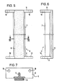
- a vertically extending connecting element 6 is provided in the region of the junction of the wall elements W1 and W2 on each long side, which is shown alone in FIGS. 5 to 7 in two views and one section.
- the connection of the upper end of the connecting element 6 in the region of the wall elements W5 and W6 is shown in FIG. 3.
- the connection of the lower end of the connecting element 6 to the floor can again be seen in FIG. 4.
- the connecting element 6 is designed as a rod-like strut or support.
- This consists of a rod profile 7 in the form of a T-iron (see FIG. 7), which is equipped in the region of its ends with a connecting plate 8 (see FIGS. 5 to 7).
- a sealing strip 9 made of foam rubber or the like is glued to the front of the rod profile 7.
- the connection plates 8 are each provided with two through holes 10.
- the releasable attachment of the rod-shaped support or strut in the region of the upper end is carried out by a screw 11 with a star grip 12.
- This screw 11 projects through the through bores 10 of the connecting plate 8 and is in engagement with a nut 13, which is attached to the inside of a reinforcing profile 14, which is part of the wall element W5 or W6 of the roof side.
- the sound hood has no base element. As can be seen from FIGS. 2 and 4, the sound hood is merely placed on a concrete floor 15. From this base 15, as can be seen from FIG. 4, threaded bolts 16 protrude with their heads. These threaded bolts 16 are anchored in the concrete floor 15 by means of dowels 17.
- the heads of the threaded bolts 16 are dimensioned and arranged such that the lower connecting plate 8 of the rod-like struts or supports with the through bores 10 can be placed on the heads, as shown in FIG.
- the rod-like struts or supports can be easily removed. All that is required is to unscrew and remove the screws 11 from the nuts 13 by means of the star grip 12. So that the upper end of the rod-like struts or supports is free. To uncouple the lower end of the rod-like struts or supports, they only have to be lifted off the heads of the threaded bolts 16 with their lower connecting plate 8. Special devices or tools are therefore not required for the dismantling of the rod-like struts or supports.
- Rod-like struts or supports of this type can not only between the wall elements W1 and W2, but also if necessary between the wall elements W2 and W4 or W1 and W3, i.e. be arranged in the corner area between the wall element on one long side and the wall element on the front side.
- the wall elements W1 and W2 on the long side are each detachably fastened to the sound hood via a total of four quick-release fasteners 5.
- these quick fasteners 5 each consist of a handle 18 which is rotatably mounted in a handle plate 19.
- the handle plate 19 is in turn connected to the wall elements W1 and W2 via two connecting screws (not shown).
- Each handle 18 is connected in a rotationally fixed manner to approximately V-shaped locking bars 20, the free ends of which engage behind the bar profile 7 of the bar-like struts or supports in the locked state (cf. FIG. 9).
- the locked position is shown in Figures 8 and 9.
- the handles 18 merely have to be pivoted into the horizontal position shown on the left in FIG. 9. Because of this pivoting, the locking bars 20 come out of engagement with the bar profile 7, so that the locking can be released and the wall elements W1 and W2 can be removed.
- the storage of the handles 18 in the handle plates 19 is designed such that the Handles only from the position shown in Figure 8 in the position shown in Figure 9 on the left side, indicated by dash-dotted lines, ie can be pivoted by a maximum of 90 °. A further pivoting of the handles 18 is not possible. In this way, the handles 18 of the quick fasteners 5 also serve as a handle for the wall elements W1 and W2, so that the additional arrangement of handles can be dispensed with.
- the preferred embodiment of the quick-release fasteners 5 shown in FIGS. 8 and 9 has a simple technical structure and can therefore be implemented relatively inexpensively.
- handles 18 including handle plate 19 commercially available parts can be used, which are less expensive than custom-made products.
- an essential element for realizing the synthesis according to the invention is the measure that openings for lines, pipes and air and ventilation channels (see FIG. 1, Reference numerals 22 and 24) are arranged exclusively in the end wall elements.
- openings for lines, pipes and air and ventilation channels see FIG. 1, Reference numerals 22 and 24
- all connections for the installation run in the area of the front wall elements W3 and W4, as a result of which the wall elements W1 and W2, including the wall elements W5 and W6 on the roof side, can be made completely free of installations and thus simple and easily dismantled.
- the front wall elements W3 and W4 are each equipped on their inside with a so-called air duct box 21.
- This air duct box 21 is connected to the outside of the sound hood via the opening 22, which is covered by a grille.
- the air duct box 21 is also connected to the interior of the acoustic hood via an opening.
- the breakthrough to the interior of the sound hood is arranged offset with respect to the breakthrough 22, so that the sound cannot pass directly from the inside to the outside in a known manner, but is deflected twice because of the staggered arrangement of the breakthroughs.
- a fan 23 is inserted into the opening in the air guide box 21 towards the interior of the acoustic hood.
- the embodiment shown in FIG. 2 is therefore a version with so-called forced ventilation, which is used in higher thermal conditions. If there are low thermal conditions, it is also possible to provide so-called self-ventilation. For this purpose, only the fan 23 is omitted. It is not necessary to change the front wall element W3, while wall element W4 can be closed without an opening 22 and air duct box 21.
Landscapes
- Engineering & Computer Science (AREA)
- Physics & Mathematics (AREA)
- Acoustics & Sound (AREA)
- Mechanical Engineering (AREA)
- General Engineering & Computer Science (AREA)
- Architecture (AREA)
- Combustion & Propulsion (AREA)
- Chemical & Material Sciences (AREA)
- Electromagnetism (AREA)
- Civil Engineering (AREA)
- Structural Engineering (AREA)
- Soundproofing, Sound Blocking, And Sound Damping (AREA)
- Building Environments (AREA)
Applications Claiming Priority (2)
| Application Number | Priority Date | Filing Date | Title |
|---|---|---|---|
| DE8809987U | 1988-08-04 | ||
| DE8809987U DE8809987U1 (de) | 1988-08-04 | 1988-08-04 | Schallhaube für Verdichteraggregate |
Publications (2)
| Publication Number | Publication Date |
|---|---|
| EP0353588A2 true EP0353588A2 (fr) | 1990-02-07 |
| EP0353588A3 EP0353588A3 (fr) | 1990-10-03 |
Family
ID=6826659
Family Applications (1)
| Application Number | Title | Priority Date | Filing Date |
|---|---|---|---|
| EP19890113609 Withdrawn EP0353588A3 (fr) | 1988-08-04 | 1989-07-24 | Capot insonorisant pour groupes-compresseurs |
Country Status (2)
| Country | Link |
|---|---|
| EP (1) | EP0353588A3 (fr) |
| DE (1) | DE8809987U1 (fr) |
Cited By (1)
| Publication number | Priority date | Publication date | Assignee | Title |
|---|---|---|---|---|
| CN103321877A (zh) * | 2013-01-22 | 2013-09-25 | 胡云翔 | Osg-e系列空气压缩机可拆卸式机箱结构设计 |
Families Citing this family (2)
| Publication number | Priority date | Publication date | Assignee | Title |
|---|---|---|---|---|
| US6321557B1 (en) * | 1999-07-02 | 2001-11-27 | Rhys Scrivener | Housing apparatus |
| CN105864343B (zh) * | 2016-05-27 | 2018-04-17 | 哈尔滨工程大学 | 一种汽油发电机的减振降噪装置 |
Family Cites Families (6)
| Publication number | Priority date | Publication date | Assignee | Title |
|---|---|---|---|---|
| US3319382A (en) * | 1964-08-24 | 1967-05-16 | Emhart Corp | Mullion assembly |
| FR1538488A (fr) * | 1967-07-13 | 1968-09-06 | Compresseurs Bernard | Perfectionnements aux centrales semi-fixes pour la production d'air ou de gaz comprimé |
| DE2317543A1 (de) * | 1973-04-07 | 1974-10-24 | Flottmann Werke Gmbh | Ortsveraenderbare arbeitsmaschine |
| DE2323238B2 (de) * | 1973-05-09 | 1975-04-30 | Demag Drucklufttechnik Gmbh, 6000 Frankfurt | Schalldämmendes zwangsbelüftetes Gehäuse für ortsfeste oder fahrbare Maschinen mit großer Geräuschentwicklung, wie Verdichter oder dergleichen |
| US3919808A (en) * | 1974-03-29 | 1975-11-18 | Donald F Simmons | Door structure |
| US4644696A (en) * | 1986-06-18 | 1987-02-24 | Pease Industries, Inc. | Patio door assembly for removable astragal |
-
1988
- 1988-08-04 DE DE8809987U patent/DE8809987U1/de not_active Expired
-
1989
- 1989-07-24 EP EP19890113609 patent/EP0353588A3/fr not_active Withdrawn
Cited By (1)
| Publication number | Priority date | Publication date | Assignee | Title |
|---|---|---|---|---|
| CN103321877A (zh) * | 2013-01-22 | 2013-09-25 | 胡云翔 | Osg-e系列空气压缩机可拆卸式机箱结构设计 |
Also Published As
| Publication number | Publication date |
|---|---|
| EP0353588A3 (fr) | 1990-10-03 |
| DE8809987U1 (de) | 1988-12-08 |
Similar Documents
| Publication | Publication Date | Title |
|---|---|---|
| DE69621707T2 (de) | Industrielle Struktur, insbesondere Generatorgehäuse, und Fabrikationsmethode hierfür | |
| DE3200210A1 (de) | Lueftungseinrichtung | |
| EP0523753A1 (fr) | Cabine démontable et transportable | |
| DE2251410C3 (de) | Rahmenaufbau | |
| EP0413784A1 (fr) | Dispositif d'aeration, eventuellement de desaeration, d'un espace. | |
| EP0185188B1 (fr) | Cabine | |
| EP0628498B1 (fr) | Conteneur | |
| EP0353588A2 (fr) | Capot insonorisant pour groupes-compresseurs | |
| DE102007021159A1 (de) | Rostdeckenschalung zur Einbindung einer Säule | |
| DE102006052854B4 (de) | Großraumkabine zur Behandlung von Werkstücken | |
| EP0186857B1 (fr) | Système de bâti à boîtiers | |
| EP0791528A2 (fr) | Structure de caisse pour un véhicule utilitaire notamment un véhicule d'intervention comme un fourgon de pompiers | |
| DE3425484A1 (de) | Versetzbare trennwand aus wandelementen und verfahren zur herstellung und demontage der wandelemente | |
| DE69300349T3 (de) | Schalldämpfende Lüftungsvorrichtung mit einem länglichen blockförmigen Gehäuse und einem spaltförmigen Lüftungskanal. | |
| DE9313426U1 (de) | Lüftungsvorrichtung für Räume | |
| CH639165A5 (en) | Panel element with a sound-insulating mat, in particular for soundproofing walls, soundproofing floors and soundproofing booths | |
| DE3301204C2 (de) | Transportbehälter | |
| DE1228640B (de) | Luftgekuehlter Waermeaustauscher, dessen Axialluefter auf einem Stuetzbock gelagert ist | |
| DE2802696C2 (fr) | ||
| EP0268197B1 (fr) | Echafaudage, plus spécialement échafaudage pour le bâtiment | |
| DE2951668A1 (de) | Begehbarer prismatischer container | |
| EP0116682A1 (fr) | Conteneur | |
| DE4415843A1 (de) | Teleskopierbarer Deckenträger | |
| AT330418B (de) | Wandkonstruktion | |
| DE2708453B2 (de) | Kastenaufbau für Fahrzeuge mit mindestens einer verschiebbaren Tür |
Legal Events
| Date | Code | Title | Description |
|---|---|---|---|
| PUAI | Public reference made under article 153(3) epc to a published international application that has entered the european phase |
Free format text: ORIGINAL CODE: 0009012 |
|
| AK | Designated contracting states |
Kind code of ref document: A2 Designated state(s): AT DE ES IT |
|
| PUAL | Search report despatched |
Free format text: ORIGINAL CODE: 0009013 |
|
| AK | Designated contracting states |
Kind code of ref document: A3 Designated state(s): AT DE ES IT |
|
| 17P | Request for examination filed |
Effective date: 19901113 |
|
| 17Q | First examination report despatched |
Effective date: 19920619 |
|
| STAA | Information on the status of an ep patent application or granted ep patent |
Free format text: STATUS: THE APPLICATION IS DEEMED TO BE WITHDRAWN |
|
| 18D | Application deemed to be withdrawn |
Effective date: 19921030 |