EP0353792A2 - Dispositif à grille pour la fusion de matériaux thermoplastiques - Google Patents
Dispositif à grille pour la fusion de matériaux thermoplastiques Download PDFInfo
- Publication number
- EP0353792A2 EP0353792A2 EP89118901A EP89118901A EP0353792A2 EP 0353792 A2 EP0353792 A2 EP 0353792A2 EP 89118901 A EP89118901 A EP 89118901A EP 89118901 A EP89118901 A EP 89118901A EP 0353792 A2 EP0353792 A2 EP 0353792A2
- Authority
- EP
- European Patent Office
- Prior art keywords
- reservoir
- grid
- thermoplastic material
- melter
- hopper
- Prior art date
- Legal status (The legal status is an assumption and is not a legal conclusion. Google has not performed a legal analysis and makes no representation as to the accuracy of the status listed.)
- Withdrawn
Links
- 229920001169 thermoplastic Polymers 0.000 title description 5
- 239000004416 thermosoftening plastic Substances 0.000 title description 5
- 239000012815 thermoplastic material Substances 0.000 claims abstract description 53
- 239000007787 solid Substances 0.000 claims abstract description 29
- 239000012768 molten material Substances 0.000 claims description 34
- 238000010438 heat treatment Methods 0.000 claims description 8
- 230000008018 melting Effects 0.000 abstract description 10
- 238000002844 melting Methods 0.000 abstract description 10
- 238000011065 in-situ storage Methods 0.000 abstract description 6
- 239000000463 material Substances 0.000 description 11
- 239000007789 gas Substances 0.000 description 10
- 239000000853 adhesive Substances 0.000 description 6
- 230000001070 adhesive effect Effects 0.000 description 6
- 239000004809 Teflon Substances 0.000 description 4
- 229920006362 Teflon® Polymers 0.000 description 4
- QVGXLLKOCUKJST-UHFFFAOYSA-N atomic oxygen Chemical compound [O] QVGXLLKOCUKJST-UHFFFAOYSA-N 0.000 description 3
- 239000011449 brick Substances 0.000 description 3
- 238000005266 casting Methods 0.000 description 3
- 239000011248 coating agent Substances 0.000 description 3
- 238000000576 coating method Methods 0.000 description 3
- 239000012943 hotmelt Substances 0.000 description 3
- 239000007788 liquid Substances 0.000 description 3
- 239000000155 melt Substances 0.000 description 3
- 239000001301 oxygen Substances 0.000 description 3
- 229910052760 oxygen Inorganic materials 0.000 description 3
- 230000002035 prolonged effect Effects 0.000 description 3
- 239000004831 Hot glue Substances 0.000 description 2
- 230000005540 biological transmission Effects 0.000 description 2
- 238000004519 manufacturing process Methods 0.000 description 2
- 230000008439 repair process Effects 0.000 description 2
- 239000004812 Fluorinated ethylene propylene Substances 0.000 description 1
- 229910052782 aluminium Inorganic materials 0.000 description 1
- XAGFODPZIPBFFR-UHFFFAOYSA-N aluminium Chemical compound [Al] XAGFODPZIPBFFR-UHFFFAOYSA-N 0.000 description 1
- 230000004888 barrier function Effects 0.000 description 1
- 238000010276 construction Methods 0.000 description 1
- 230000001419 dependent effect Effects 0.000 description 1
- 230000000694 effects Effects 0.000 description 1
- 230000008030 elimination Effects 0.000 description 1
- 238000003379 elimination reaction Methods 0.000 description 1
- HQQADJVZYDDRJT-UHFFFAOYSA-N ethene;prop-1-ene Chemical group C=C.CC=C HQQADJVZYDDRJT-UHFFFAOYSA-N 0.000 description 1
- 230000005484 gravity Effects 0.000 description 1
- 238000003754 machining Methods 0.000 description 1
- 238000005058 metal casting Methods 0.000 description 1
- 230000004048 modification Effects 0.000 description 1
- 238000012986 modification Methods 0.000 description 1
- 229920009441 perflouroethylene propylene Polymers 0.000 description 1
- 230000002093 peripheral effect Effects 0.000 description 1
- 230000002028 premature Effects 0.000 description 1
- 230000003134 recirculating effect Effects 0.000 description 1
- 238000007789 sealing Methods 0.000 description 1
- 239000011343 solid material Substances 0.000 description 1
- 238000007711 solidification Methods 0.000 description 1
- 230000008023 solidification Effects 0.000 description 1
- 125000006850 spacer group Chemical group 0.000 description 1
Images


Classifications
-
- B—PERFORMING OPERATIONS; TRANSPORTING
- B29—WORKING OF PLASTICS; WORKING OF SUBSTANCES IN A PLASTIC STATE IN GENERAL
- B29B—PREPARATION OR PRETREATMENT OF THE MATERIAL TO BE SHAPED; MAKING GRANULES OR PREFORMS; RECOVERY OF PLASTICS OR OTHER CONSTITUENTS OF WASTE MATERIAL CONTAINING PLASTICS
- B29B13/00—Conditioning or physical treatment of the material to be shaped
- B29B13/02—Conditioning or physical treatment of the material to be shaped by heating
- B29B13/022—Melting the material to be shaped
Definitions
- This invention relates to apparatus for melting and dispensing thermoplastic materials.
- thermoplastic materials or so-called "hot melt” materials were converted from a solid to a molten state in a tank having heated walls. The melted material was maintained in the molten state in the tank in sufficient volume to supply one or more applicators or dispensers. If the job or application required a substantial volume of hot melt adhesive, a substantially large volume of material was required to be maintained in the molten or melted state to meet that need. That substantial volume usually necessitated a long warm up or start up time for the apparatus, as well as prolonged exposure of at least some of the molten material to heat and/or to oxygen. Since many thermoplastic materials oxidize, char or degrade as a result of prolonged exposure to heat and/or oxygen, there was a need for a more efficient melter.
- thermoplastic material melter The need for a more efficient thermoplastic material melter was met or satisfied by a so-called grid type hot melt applicator wherein the solid thermoplastic material was melted upon the top of a heated grid and then supplied through the grid to a relatively small holding reservoir from which the molten material was pumped to a dispenser.
- the grid type applicator was capable of melting a very high throughput of thermoplastic material in a very short time so that as a result, the molten adhesive was not maintained in a molten state for prolonged periods of time to char, oxidize, or otherwise degrade.
- a typical grid type hot melt applicator is disclosed in U.S. Patent No. 3,964,645.
- the high melt rate and the efficiency of the grid type applicator creates a problem when that unit is used to dispense molten material at a lesser rate than that for which it is designed.
- the melter is operative to melt greater quantities of the thermoplastic material than is used with the result that the molten material fills the molten material reservoir, backs up beyond the melter, and eventually melts back into the hopper of solid thermoplastic material.
- Petrecca for "Thermoplastic Melting and Dispensing Apparatus” there is disclosed one solution to the problem of leakage at the sealed joints of a grid type applicator.
- the solution disclosed in this patent is to coat the inside surface of the hopper walls with a coating of high temperature, fluorinated ethylene propylene ("Teflon").
- Teflon fluorinated ethylene propylene
- prior art grid type applicators require replacement of the grids of the applicators. This requirement is generally attributable to a failed heater cartridge contained within the grid. Theoretically, failure of a heater cartridge requires only the replacement of the failed heater cartridge. In practice, though, the bores in the grid within which the cartridge heaters are mounted can become contaminated with molten thermoplastic material or become bent or misaligned while the cartridge is contained therein with the result that it is often difficult to remove a single failed cartridge from the grid. In that case, it may become less expensive to simply replace the whole grid. It has therefore been another objective of this invention to provide an improved grid type applicator wherein the heater grids have a longer life than prior art heater grids.
- Still another objective of this invention has been to provide an improved heater grid which is more economical and less expensive to manufacture than prior art heater grids.
- this invention is partially predicated upon the concept of casting a single continuous heater element into a heater grid, rather than utilizing multiple individual heater cartridges within the grid.
- cast in situ heaters of a melter are less expensive to manufacture and have a longer life than melters having cartridge-style heaters.
- the reduced cost of the grid melter is primarily attributable to the elimination of the cartridges and the need for machining the bores within which the cartridges are mounted.
- the cast in situ heater also has been found to have a much longer life than individual heater cartridges and to eliminate the often difficult problem of removing and replacing failed cartridges.
- Another aspect of this invention is predicated upon the concept of providing recesses or cavities on the underside of the grid melter.
- These recesses or cavities act as air or gas pockets within which air or gas is entrapped.
- these air or gas pockets serve as expansion chambers within which the thermoplastic material may freely expand without creating excessive pressures beneath the solid top of the thermoplastic material.
- the provision of these gas pockets acting as accumulators or expansion chambers reduces pressure buildup, which in turn results in extension of the seal life between the reservoir and the grid, or between the grid and the hopper.
- the grid melter of this invention comprises a reservoir atop which there is mounted a heated grid having a cast in situ heater element therein. On the underside of the heated grid there are recesses or cavities which function as air or gas pockets for the reception of molten adhesive upon expansion of that adhesive.
- a hopper for receiving the solid thermoplastic material is mounted above the grid melter, there being a sealed joint between the hopper and the grid and between the grid and the shallow reservoir.
- this grid melter has improved melting capability over prior art cartridge-style grid melters in the melting of block or brick forms of material, and it has improved life of the heater grid. It is also characterized by reduced seal failure in the joints between the hopper and the grid and in the joint between the grid and the reservoir.
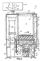
- thermoplastic material melting and dispensing apparatus 5 of this invention comprises a housing or covering shroud 10 within which there is located a hopper 11, a heated grid 12 ( Figures 2, 3 and 4), a reservoir 13, a pair of gear pumps 14, 14a, and a manifold block 15.
- Solid thermoplastic material 16 in the form of chunks or blocks are placed in the top of the hopper 11 from which they flow through the open bottom into contact with the top surface of the grid 12.
- the grid 12 is heated so that surface contact of the solid thermoplastic material with the top surface of the grid causes the solid thermoplastic material to be melted and converted to a molten state.
- the molten thermoplastic material 17 then flows downwardly through bottom passageways 18 in the grid melter into the reservoir 13 located immediately beneath the melter 12.
- the reservoir has a sloping bottom which directs the molten material toward the inlet 20 of a gate valve 21.
- This gate valve 21 is then operative to direct the molten thermoplastic material into the inlets of the pumps 14, 14a, or alternatively, depending upon the position of the gate valve, to a reservoir dump port 22. Assuming that the gate valve is positioned so as to direct the flow to the pumps 14, 14a, those pumps then move the molten material into the manifold block 15 from whence it is directed to one or more conventional applicators or dispensers (not shown) via hoses or conduits 23.
- the housing 10 comprises a base 25 and a cover 26 mounted atop the base.
- the cover encloses two sections of the applicator, the melt section 27 and the control section 28.
- the two sections are separated by an insulated barrier (not shown).
- Within the control section 28 are all of the electrical components for controlling the temperature of the components throughout the system.
- This console 29 is rotatably mounted atop the control section 28 and is electrically connected to control components of the applicator via electrical leads (not shown) which are contained within a conduit 30.
- the console 29 is mounted atop the control section 28 of the housing by a connector 31 which permits the console to be rotated, as indicated by the arrow A ( Figure 1), or vertically adjusted as indicated by the arrow B. These adjustments enable the operator to more easily and conveniently interface with the controls and with the diagnostic indicators on the face 29a of the console. These adjustments also enable the applicator 5 to be positioned in the most convenient location relative to the operator's normal work station.
- the top of the housing 10 has an opening beneath which there is located the hopper 11.
- the hopper comprises a vertical tube-shaped aluminum member 32, the bottom 33 of which is open and the top of which is closed by a lid 34.
- a flange 35 which is bolted to the top of the heated grid melter 12 (see Figure 3).
- the heated grid 12 comprises a receptacle into which solid thermoplastic material flows from the hopper 11.
- This receptacle comprises four side walls 37 and a bottom 38.
- the grid 12 comprises a plurality of spaced parallel ribs 39, each rib of which is shaped as a tall and thin triangle in cross section. These parallel ribs all extend from one side wall 37 to the opposite side wall 37.
- each triangularly shaped rib has a downwardly open recess or cavity 45 formed therein. These recesses extend for the full length of each rib and, as explained more fully hereinafter, function as air or gas pockets when the grid melter is used to melt solid thermoplastic material and the molten material raises up over the bottom surface of the grid melter.
- the grid melter 12 is formed as an integral metal casting. This casting has external lugs 46 formed on each end and side wall 37. Each lug is vertically bored to accommodate bolts 47 for mounting the hopper on top of the grid melter 12 and the grid melter upon the top of the reservoir 13. Between the bottom of the hopper and the top of the grid there is a seal 48 which is located within a peripheral groove 49 of the grid. This seal 48 forms a liquid and gas tight seal between the hopper and grid.
- This element 50 Cast in situ into the grid melter there is a sinuous shaped electrical resistance heater element 50.
- This element 50 has straight horizontal sections 51 extending for the length of each rib of the grid melter and has 180° radiused turn sections 52 imbedded in the end walls 37.
- the opposite ends 53, 54 of this electrical heating element 50 extend from one side wall 37 of the grid melter and are adapted to be connected to a source of electrical power.
- a temperature sensor device mounted within the grid melter. This device is used to control and maintain the temperature of the grid melter at a preset temperature.
- the ribs 39 in cross section are shaped as tall, thin triangles. This configuration has been found to provide optimum melt rate and sufficient strength to support large loads of material found in this type of melter.
- the reservoir 13 comprises an open top, closed bottom receptacle which is fixedly mounted to the bottom of the grid melter 12.
- the reservoir has inwardly sloping side walls 59, end walls 102, 102a and bottom walls 60, all of which slope toward a central bottom opening 61.
- the gate valve 21 is mounted within this opening 61.
- the attachment of the reservoir 13 to the bottom of the grid melter 12 is by means of a flange 62 which extends outwardly from the top edge of the side walls 63 of the reservoir.
- the top surface of this flange 62 has a shallow groove formed therein within which there is fitted a liquid and gas tight seal 64.
- the bolts 47 which extend through the external lugs 46 of the grid melter extend through the flange 62 of the reservoir so as to secure the grid melter 12 in an assembled relationship between the flange 35 of the hopper and the flange 62 of the reservoir.
- a sleeve-type spacer 71 surrounds each bolt and determines the spacing between the shelf section 24 of the housing 26 and the flange 62 of the reservoir.
- thermoplastic material applicators incorporate continuous recirculation of the molten thermoplastic material into the apparatus. If the molten material is to be recirculated, a conventional recirculating line (not shown) in the manifold block 15 is connected via a pressure control/circulation valve (not shown) to return passageways 80, 81 ( Figures 6 and 7) in the bottom section 72 of the reservoir.
- the bores 73, 74 within which the pumps 14, 14a are mounted extend transversly through the bottom section 72 of the pump reservoir.
- a pair of heaters 90, 91 Extending longitudinally of the bottom section 72 of the reservoir there are a pair of heaters 90, 91. Both of these heaters comprise a single, electrical resistance heating element which is preferably cast in situ into the casting from which the reservoir 13 is manufactured.
- One of these heaters 90 which is best illustrated in Figure 7, comprises four horizontal runs 90a, 90b, 90c, and 90d of heater element interconnected at the ends by 180° arcuate end sections or bends 93 such that in elevational profile, the complete heater element 90 is generally W-shaped.
- the ends 94, 95 of this heater element extend outwardly from the side wall of the reservoir and are connected by conventional electrical leads (not shown) to controls contained within the control section 28 of the housing 26.
- the other heater 91 is best illustrated in Figure 6. With reference to this Figure, it will be seen that this heater has an upper horizontal run 91 and a lower horizontal run 91b interconnected by a vertical section 96. The lower run has an upwardly extending loop 97 therein which is located between the two pumps 14, 14a and wraps around the dump port 22 of the reservoir. The ends 98, 99 of the heater element 91 extend outwardly from the side wall of the reservoir and are connected via electrical leads (not shown) to controls contained within the control section 28 of the housing 26.
- the two reservoir heaters 90, 91 differ in size and shape. These heaters are sized and balanced so as to be controllable from a single thermostat control 93 while still maintaining an even temperature throughout the reservoir.
- a drain plug 100 is mounted within the threaded dump port or bore 22 of the reservoir. This bore extends through the wall of the reservoir and intersects the central opening 61. Depending upon the setting of the gate valve 21, the bottom of the reservoir is either open and connected to the inlets of the pumps 14, 14a, or to the drain plug receiving bore 22. This plug is located at this position in the reservoir so as to enable the reservoir to be drained of molten thermoplastic material without the molten material having to pass through the pumps in the event that it should ever become necessary to drain the reservoir quickly.
- This shield 103 ensures that all of the molten material passes over the end walls 102 before flowing onto the bottom wall 60 and entering the central opening 61 in the reservoir. Quite commonly, the application temperature of the molten material is greater than the temperature at which it converts from the solid to the molten state and falls through the openings 18 and the grid melter. The material is then further heated within the reservoir as a consequence of surface contact of the material with the surfaces of the reservoir before the molten material flows into the gate valve 20.
- the shield 103 functions to ensure that the molten material is exposed to and, if necessary, raised in temperature to the desired temperature at which it is to enter the pumps 14, 14a.
- the opening 61 in the bottom of the reservoir which receives the gate valve 21 is shaped as a stepped bore which extends vertically through the bottom of the reservoir 13.
- the gate valve 21 which fits into this opening 61 is shaped as an open top cup 105 having a shaft 106 depending therefrom.
- the shaft 106 fits within the smaller diameter lower end section 107 of the bore 61 and is rotatable therein. Rotation of the shaft 106 is effected manually by rotation of a handle 108 which extends radially from the shaft 106. Rotation of the handle is limited to 90° by engagement of a stop pin 109 which extends transversly through the shaft 106 and is engageable with abutments 110 formed on the underside of the bottom section 72 of the reservoir.
- a sealing O-ring 111 mounted within an annular groove of the shaft. This O-ring also functions to frictionally hold the gate valve 21 in either of its two positions of adjustment.
- openings 112, 113 there are a pair of opposed openings 112, 113 in the side wall of the upper end section or cup-shaped section 105 of the gate valve 21. In one position of the gate valve, these openings 105, 106 are aligned with the passages 75, 76 which open to the inlet ports of the pumps 14, 14a, respectively. In the other position of the gate valve, in which the valve is rotated 90° from the position illustrated in Figure 3, one of the openings 112, 113 is aligned with the drain port 22. In this latter position of the gate valve in which one of the openings 112, 113 is aligned with the drain port 22, the passages 75, 76 to the inlet ports of the pump are blocked by solid portions of the cup-shaped upper end section 95 of the gate valve.
- the handle 108 In order to operate the gate valve and move it between its two positions, the handle 108 must be manually grasped and rotated. To that end, the base section 25 of the housing 10 has an opening 114 through which the handle 98 may be accessed ( Figure 2).
- cover or strainer plate 104 secured over the open top of the gate valve.
- This cover or strainer 115 has apertures or holes in it sized so that it is effective to screen out nuts, bolts, or large chunks of solid thermoplastic material from entering the pumps or clogging the passageways to the entry ports of the pumps.
- pumps 14, 14a are identical gear pumps, they can be of any construction compatible with the intended use of the apparatus. Further, they need not both be of the same size or style. A complete description of one appropriate type of gear pump may be found in U.S. Patent No. 3,964,675. Accordingly, these pumps have not been described in detail herein.
- Each pump 14, 14a is mounted within one of the bores 73, 74 of the reservoir bottom section 72 and has an inlet port 77, 77a open to the passages 75, 76, respectively.
- Each pump 14, 14a has an outlet port connected via passageways 78, 79 in the reservoir bottom section 72 to passages in the manifold block 15.
- thermoplastic material there are two pumps connected by the gate valve 20 to the bottom of the reservoir 13 and operative to supply molten thermoplastic material to the manifold block 15.
- the manifold block is ported such that the molten material flowing from the outlet ports of the pumps 14, 14a flows to selected outlet ports of the manifold block 15. Those outlet ports are in turn connected to dispensers (not shown) via the hoses 23.
- the pumps 14, 14a are independently driven in rotation by drive motors 115, 115a.
- Each drive motor 115, 115a is operatively connected to the input drive shaft of one pump via a gear or transmission box 116, 116a, the output shafts of which are connected via a chain and sprocket drive 117, 117a to the input shafts 118, 118a of the pumps 14, 14a.
- the gear or transmission boxes 116, 116a are each mounted upon a pivotally supported mounting block 120, 120a.
- Each of these blocks 120, 120a is pivotally supported from a pivot post 121, 121a and has an arcuate slot 122, 122a through which there extends a bolt 123, 123a.
- this quick disconnect characteristic of the drive to the pumps 14, 14a from the drive shafts of the motors enables the pumps to be very quickly removed and replaced or repaired.
- the pumps are particularly easily and quickly replaced because there is no need to drain the reservoir 13 before removing the pump for repair or replacement. All that is required to remove a pump 14, 14a is to close the gate valve, disconnect the chain of the associated chain and sprocket drive 117, 117a and unbolt the pump from its mounting within the bottom section 72 of the reservoir within which it is mounted. There is no need to drain the reservoir, and disconnection of the drive to the pump requires no more than loosening of the bolt 123, 123a so as to place slack in the chain of the chain and sprocket drive 117, 117a.
- the heater grid described hereinabove is constructed so as to prevent molten thermoplastic material from leaking through the seals 48, 64 between the hopper, the grid melter, and the reservoir upon remelt of solid thermoplastic material contained within the hopper.
- the molten material adheres to the inside walls of the hopper 11 upon solidification. Upon restarting of the apparatus, that solidified material contained in the hopper must be remelted. However, because most thermoplastic materials have poor heat conductive qualities, it often takes a long time to restart the apparatus and remelt all of the formerly molten, but now solidified, material 126 contained within the hopper. While this remelt is occurring, molten material will be entrapped beneath a solid "bridge" or cap 126 of formerly molten, but now solid, thermoplastic material adhered to the inside walls of the hopper.
- That solid "bridge” or cap serves to entrap any pressure buildup which occurs upon thermal expansion of the remelted material 17 entrapped beneath the plug 126.
- Many thermoplastic materials, and particularly pressure sensitive thermoplastic materials have a high coefficient of expansion with the result that when these materials are remelted in the hopper, there is a substantial pressure buildup beneath the solid plug 126 in the hopper.
- that plug and the resulting pressure often built up to a pressure sufficient to force molten material to squeeze through the seals 48, 64 between the hopper and the grid or between the grid and the reservoir with the result that the apparatus sprang a leak or blew out the seals.
- each of the ribs 39 of the grid melter function to prevent pressure buildup under these conditions. Air or gas becomes entrapped within those recesses 45 when the liquid level rises above the bottom of the grid melter. Consequently, under the conditions described hereinabove, when there is a solid bridge or cap over the top of the grid melter and molten material beneath the grid melter, that pressure buildup which would otherwise occur upon expansion of the molten material is accommodated by the air or gas filled recesses 45 which now function as pressure accumulators to accommodate that expansion of the molten material. Consequently, there is no pressure buildup sufficient to squeeze molten material through the seals 48, 64 or to cause the seals to spring a leak.
- the desired temperatures for each of the heaters or heater sections of the applicator is initially inputted to the control console 29 by actuation of the appropriate controls on the face 29a of that console. After the apparatus has had time to warm up or to come up to temperature, that condition is indicated on the readout displays on that same face 29a of the console.
- solid chunks or blocks of thermoplastic material contained within the hopper 11 is melted as a consequence of surface contact of the thermoplastic material with the ribs 39 or side walls of the heated grid 12. That molten material then falls through the passages 18 between the ribs into the reservoir.
- thermoplastic material is then routed by the gate valve 21 to the inlets of the pumps 14, 14a and from those pumps, to the manifold block 15.
- the manifold block in turn routes the molten thermoplastic via hoses 23 to conventional manual or automatic dispensers.
Landscapes
- Physics & Mathematics (AREA)
- Thermal Sciences (AREA)
- Engineering & Computer Science (AREA)
- Mechanical Engineering (AREA)
- Coating Apparatus (AREA)
- Heating, Cooling, Or Curing Plastics Or The Like In General (AREA)
- Injection Moulding Of Plastics Or The Like (AREA)
Applications Claiming Priority (2)
| Application Number | Priority Date | Filing Date | Title |
|---|---|---|---|
| US06/792,673 US4771920A (en) | 1985-10-29 | 1985-10-29 | Thermoplastic grid melter |
| US792673 | 1985-10-29 |
Related Parent Applications (2)
| Application Number | Title | Priority Date | Filing Date |
|---|---|---|---|
| EP86113615A Division EP0220530B1 (fr) | 1985-10-29 | 1986-10-02 | Dispositif à grille pour la fusion de matériaux thermoplastiques |
| EP86113615.8 Division | 1986-10-02 |
Publications (2)
| Publication Number | Publication Date |
|---|---|
| EP0353792A2 true EP0353792A2 (fr) | 1990-02-07 |
| EP0353792A3 EP0353792A3 (fr) | 1990-11-28 |
Family
ID=25157684
Family Applications (2)
| Application Number | Title | Priority Date | Filing Date |
|---|---|---|---|
| EP19890118901 Withdrawn EP0353792A3 (fr) | 1985-10-29 | 1986-10-02 | Dispositif à grille pour la fusion de matériaux thermoplastiques |
| EP86113615A Expired EP0220530B1 (fr) | 1985-10-29 | 1986-10-02 | Dispositif à grille pour la fusion de matériaux thermoplastiques |
Family Applications After (1)
| Application Number | Title | Priority Date | Filing Date |
|---|---|---|---|
| EP86113615A Expired EP0220530B1 (fr) | 1985-10-29 | 1986-10-02 | Dispositif à grille pour la fusion de matériaux thermoplastiques |
Country Status (4)
| Country | Link |
|---|---|
| US (1) | US4771920A (fr) |
| EP (2) | EP0353792A3 (fr) |
| JP (1) | JPH0767547B2 (fr) |
| DE (1) | DE3673320D1 (fr) |
Cited By (3)
| Publication number | Priority date | Publication date | Assignee | Title |
|---|---|---|---|---|
| EP0743151A3 (fr) * | 1995-05-18 | 1997-07-23 | Illinois Tool Works | Appareil de fusion |
| EP2650095A1 (fr) * | 2012-04-13 | 2013-10-16 | HAUNI Maschinenbau AG | Dispositif de fusion de colle chaude |
| EP4032620A1 (fr) | 2021-01-22 | 2022-07-27 | Robatech AG | Appareil de fusion permettant de fourniture un milieu fondu |
Families Citing this family (45)
| Publication number | Priority date | Publication date | Assignee | Title |
|---|---|---|---|---|
| US6740851B2 (en) | 2002-09-27 | 2004-05-25 | Nordson Corporation | Quick connect hot melt unit |
| DE3733029C1 (de) * | 1987-09-30 | 1989-02-23 | Claassen Henning J | Vorrichtung zum Verfluessigen eines hochpolymeren,thermopolastischen Werkstoffes |
| ATE140436T1 (de) * | 1987-12-09 | 1996-08-15 | May Coating Technologies Inc | Spender für schmelzbare klebemittel |
| US5013892A (en) * | 1988-08-18 | 1991-05-07 | Anthony Monti | Electrical melting apparatus of confectionery products |
| US5238468A (en) * | 1991-08-19 | 1993-08-24 | Nordson Corporation | Collection device for gaseous emissions |
| US5257723A (en) * | 1992-06-02 | 1993-11-02 | Nordson Corporation | Bulk melter with material recirculation |
| US5814790A (en) * | 1995-10-04 | 1998-09-29 | Nordson Corporation | Apparatus and method for liquifying thermoplastic material |
| US5657904A (en) * | 1995-10-17 | 1997-08-19 | Nordson Corporation | High flow melting grid and melter unit |
| US5715972A (en) * | 1995-10-30 | 1998-02-10 | Nordson Corporation | Molten thermoplastic material supply system with isolated grid |
| US5680961A (en) * | 1995-10-30 | 1997-10-28 | Nordson Corporation | Configurable system for supplying molten thermoplastic material |
| US5853243A (en) * | 1996-10-03 | 1998-12-29 | Warner-Lambert Company | High molecular weight elastomer processing system for chewing gum |
| US6056431A (en) * | 1997-09-05 | 2000-05-02 | Eastman Kodak Company | Modified passive liquefier batch transition process |
| US6039217A (en) * | 1998-04-07 | 2000-03-21 | Nordson Corporation | Apparatus and method for thermoplastic material handling |
| US6019255A (en) * | 1998-04-22 | 2000-02-01 | Tanury; Bryan | Modular adhesive sealant heating system |
| US6175101B1 (en) * | 1998-09-24 | 2001-01-16 | Nordson Corporation | Thermoplastic material melting unit having high throughput and heating capacity |
| DE10042478B4 (de) * | 2000-08-29 | 2007-03-15 | Bühler AG | Verfahren zum Aufschmelzen von Polymergranulat sowie Abschmelzelement |
| CN101118030B (zh) * | 2001-10-29 | 2013-01-09 | 诺德森公司 | 热熔性胶粘剂定量配料装置 |
| US6809294B2 (en) * | 2003-02-12 | 2004-10-26 | The Regents Of The University Of California | Apparatus for dispensing pavement sealants |
| US20050093403A1 (en) * | 2003-10-31 | 2005-05-05 | Nordson Corporation | Support and storage system for an adhesive dispensing unit |
| US7315691B1 (en) * | 2004-01-15 | 2008-01-01 | Wax Figures, Inc. | Wax dispenser for hot wax applications |
| DE202004001038U1 (de) * | 2004-01-24 | 2004-04-08 | Delle Vedove Maschinenbau Gmbh | Tandem-Kolbenschmelzer |
| US7015427B1 (en) | 2004-11-19 | 2006-03-21 | Nordson Corporation | Apparatus and method for melting and supplying thermoplastic material to a dispenser |
| JP5129147B2 (ja) * | 2005-10-17 | 2013-01-23 | イリノイ トゥール ワークス インコーポレイティド | 遠隔ホットメルト接着剤計量ステーション |
| EP1963226A2 (fr) * | 2005-10-21 | 2008-09-03 | CH & I Technologies, Inc. | Systeme integre de transfert et distribution de matieres |
| FR2898883B1 (fr) * | 2006-03-27 | 2008-06-20 | Skf Aerospace France Soc Par A | Procede et installation de depotage d'une resine thermodurcissable |
| EP1950018B1 (fr) | 2007-01-29 | 2014-10-08 | Nordson Corporation | Appareil et méthode de distribution d'un matériau fusible |
| US7900800B2 (en) * | 2007-10-19 | 2011-03-08 | Nordson Corporation | Dispensing apparatus with heat exchanger and method of using same |
| US8272537B2 (en) * | 2008-04-17 | 2012-09-25 | Nordson Corporation | Valveless liquid dispenser |
| US8096648B2 (en) * | 2009-01-30 | 2012-01-17 | Xerox Corporation | Ink melt device with solid state retention and molten ink pass-through |
| US8136933B2 (en) * | 2009-01-30 | 2012-03-20 | Xerox Corporation | Solid ink melt tub with corrugated melt region and offset outlet |
| US8240829B2 (en) * | 2009-12-15 | 2012-08-14 | Xerox Corporation | Solid ink melter assembly |
| US8313183B2 (en) * | 2010-11-05 | 2012-11-20 | Xerox Corporation | Immersed high surface area heater for a solid ink reservoir |
| US9174231B2 (en) | 2011-10-27 | 2015-11-03 | Graco Minnesota Inc. | Sprayer fluid supply with collapsible liner |
| EP2771126B1 (fr) | 2011-10-27 | 2019-09-18 | Graco Minnesota Inc. | Dispositif de fusion |
| US9061316B2 (en) * | 2011-10-28 | 2015-06-23 | Nordson Corporation | Mountable device for dispensing heated adhesive |
| EP2776171A1 (fr) * | 2011-11-07 | 2014-09-17 | Graco Minnesota Inc. | Système de fusion |
| US10099242B2 (en) * | 2012-09-20 | 2018-10-16 | Nordson Corporation | Adhesive melter having pump mounted into heated housing |
| US9421696B2 (en) * | 2013-03-15 | 2016-08-23 | Jason Womack | Polystyrene product remanufacturing apparatus and methods of use |
| WO2016047732A1 (fr) * | 2014-09-25 | 2016-03-31 | センチュリーイノヴェーション株式会社 | Récipient de fusion, dispositif d'injection utilisant celui-ci, moulage par injection et procédé de fabrication de celui-ci, et procédé de fabrication de matériau de jonction inter-éléments |
| US9796492B2 (en) | 2015-03-12 | 2017-10-24 | Graco Minnesota Inc. | Manual check valve for priming a collapsible fluid liner for a sprayer |
| KR20180018693A (ko) | 2015-06-11 | 2018-02-21 | 노드슨 코포레이션 | 카트리지형 유체 분배 장치 |
| US9650206B2 (en) * | 2015-07-24 | 2017-05-16 | Dynamic Aur Inc. | Conveying systems |
| US10675653B2 (en) | 2017-02-07 | 2020-06-09 | Nordson Corporation | Motorized cartridge type fluid dispensing apparatus and system |
| CN115739435A (zh) | 2019-05-31 | 2023-03-07 | 固瑞克明尼苏达有限公司 | 手持式流体喷雾器 |
| CN113926381B (zh) * | 2021-08-19 | 2023-09-26 | 安徽华星化工有限公司 | 一种杀虫单磺化用大苏打投放工艺 |
Family Cites Families (17)
| Publication number | Priority date | Publication date | Assignee | Title |
|---|---|---|---|---|
| US2203620A (en) * | 1938-02-19 | 1940-06-04 | Beed Prentice Corp | Apparatus for treating thermoplastic products |
| FR987112A (fr) * | 1949-03-30 | 1951-08-09 | Perfectionnement aux grilles de fusion | |
| US2809772A (en) * | 1955-05-02 | 1957-10-15 | Kamborian Jacob S | Apparatus for melting and dispensing thermoplastic adhesive |
| US3531624A (en) * | 1968-06-13 | 1970-09-29 | Farrel Corp | Heater for extrusion press container |
| US3585361A (en) * | 1969-06-18 | 1971-06-15 | Nordson Corp | Supply system for heating and dispensing molten thermoplastic material |
| US3792801A (en) * | 1971-10-29 | 1974-02-19 | Nordson Corp | Thermoplastic applicator with self-cleaning supply reservoir |
| US3876105A (en) * | 1974-02-25 | 1975-04-08 | Possis Corp | Hot melt machine |
| US3964645A (en) * | 1975-02-12 | 1976-06-22 | Nordson Corporation | Apparatus for melting and dispensing thermoplastic material |
| US4009974A (en) * | 1975-02-12 | 1977-03-01 | Nordson Corporation | Method and apparatus for pumping viscous material |
| DE2836545C2 (de) * | 1978-08-21 | 1984-11-08 | Fa. Henning J. Claassen, 2120 Lüneburg | Gerät zum Verflüssigen von Schmelzmassen, insbesondere Schmelzklebestoffen |
| DE3008779C2 (de) * | 1980-03-07 | 1985-08-08 | Reich Spezialmaschinen GmbH, 7440 Nürtingen | Schmelz- und Auftragsvorrichtung für Schmelzkleber |
| DE3070405D1 (en) * | 1980-12-29 | 1985-05-02 | Alfa Laval Nv | Apparatus for melting refrigerated butter |
| US4474311A (en) * | 1981-07-31 | 1984-10-02 | Nordson Corporation | Thermoplastic melting and dispensing apparatus |
| US4485942A (en) * | 1981-09-14 | 1984-12-04 | Nordson Corporation | Apparatus for melting and dispensing thermoplastic material |
| US4456151A (en) * | 1981-09-14 | 1984-06-26 | Nordson Corporation | Housing for apparatus for melting and dispensing thermoplastic material |
| US4485941A (en) * | 1981-09-14 | 1984-12-04 | Nordson Corporation | Apparatus for melting and dispensing thermoplastic material |
| US4667850A (en) * | 1985-10-28 | 1987-05-26 | Nordson Corporation | Thermoplastic grid melter |
-
1985
- 1985-10-29 US US06/792,673 patent/US4771920A/en not_active Expired - Fee Related
-
1986
- 1986-10-02 EP EP19890118901 patent/EP0353792A3/fr not_active Withdrawn
- 1986-10-02 EP EP86113615A patent/EP0220530B1/fr not_active Expired
- 1986-10-02 DE DE8686113615T patent/DE3673320D1/de not_active Expired - Lifetime
- 1986-10-29 JP JP61255958A patent/JPH0767547B2/ja not_active Expired - Fee Related
Cited By (5)
| Publication number | Priority date | Publication date | Assignee | Title |
|---|---|---|---|---|
| EP0743151A3 (fr) * | 1995-05-18 | 1997-07-23 | Illinois Tool Works | Appareil de fusion |
| EP2650095A1 (fr) * | 2012-04-13 | 2013-10-16 | HAUNI Maschinenbau AG | Dispositif de fusion de colle chaude |
| EP4032620A1 (fr) | 2021-01-22 | 2022-07-27 | Robatech AG | Appareil de fusion permettant de fourniture un milieu fondu |
| CN114797680A (zh) * | 2021-01-22 | 2022-07-29 | 乐佰得控股集团 | 用于提供熔融的介质的熔化设备 |
| US11766808B2 (en) | 2021-01-22 | 2023-09-26 | Robatech Ag | Melter for preparing a molten medium |
Also Published As
| Publication number | Publication date |
|---|---|
| EP0353792A3 (fr) | 1990-11-28 |
| EP0220530A3 (en) | 1988-06-22 |
| EP0220530B1 (fr) | 1990-08-08 |
| DE3673320D1 (de) | 1990-09-13 |
| US4771920A (en) | 1988-09-20 |
| EP0220530A2 (fr) | 1987-05-06 |
| JPS62102855A (ja) | 1987-05-13 |
| JPH0767547B2 (ja) | 1995-07-26 |
Similar Documents
| Publication | Publication Date | Title |
|---|---|---|
| EP0220530B1 (fr) | Dispositif à grille pour la fusion de matériaux thermoplastiques | |
| US4667850A (en) | Thermoplastic grid melter | |
| EP0220529B1 (fr) | Dispositif à grille pour la fusion de matériaux thermoplastiques | |
| US4474311A (en) | Thermoplastic melting and dispensing apparatus | |
| US3981416A (en) | Apparatus for melting and dispensing thermoplastic material | |
| CA1179842A (fr) | Dispositif de fusion et de debitage de matiere thermoplastique | |
| EP0074839B1 (fr) | Dispositif pour faire fondre et distribuer de la matière thermoplastique | |
| US3964645A (en) | Apparatus for melting and dispensing thermoplastic material | |
| EP1772196B1 (fr) | Système adhésif thermofusible présentant un collecteur central et une capacité de chauffage local | |
| US4456151A (en) | Housing for apparatus for melting and dispensing thermoplastic material | |
| US3531023A (en) | Process and apparatus for melting and dispensing thermoplastic material | |
| US4009974A (en) | Method and apparatus for pumping viscous material | |
| EP1115542A1 (fr) | Unite de melange pour matieres thermoplastiques a grand debit et a capacite de chauffage elevee | |
| US4898302A (en) | Apparatus for melting and dispensing thermoplastic material | |
| US6003732A (en) | Heated platen for liquefying thermoplastic materials | |
| EP1439917B1 (fr) | Filtre et indicateur de niveau destines a un systeme d'adhesif thermofusible | |
| EP2332708A2 (fr) | Appareil de distribution d'un matériau fusible | |
| EP0743151B1 (fr) | Appareil de fusion | |
| JPS5953105B2 (ja) | 熱可塑性材料を溶融させ使用に供するための装置 | |
| US5890514A (en) | Shutoff valve and filter in thermoplastic material supply system | |
| JP4176243B2 (ja) | 溶融紡糸装置 |
Legal Events
| Date | Code | Title | Description |
|---|---|---|---|
| PUAI | Public reference made under article 153(3) epc to a published international application that has entered the european phase |
Free format text: ORIGINAL CODE: 0009012 |
|
| 17P | Request for examination filed |
Effective date: 19891011 |
|
| AC | Divisional application: reference to earlier application |
Ref document number: 220530 Country of ref document: EP |
|
| AK | Designated contracting states |
Kind code of ref document: A2 Designated state(s): CH DE FR GB LI |
|
| PUAL | Search report despatched |
Free format text: ORIGINAL CODE: 0009013 |
|
| AK | Designated contracting states |
Kind code of ref document: A3 Designated state(s): CH DE FR GB LI |
|
| 17Q | First examination report despatched |
Effective date: 19920416 |
|
| STAA | Information on the status of an ep patent application or granted ep patent |
Free format text: STATUS: THE APPLICATION IS DEEMED TO BE WITHDRAWN |
|
| 18D | Application deemed to be withdrawn |
Effective date: 19931123 |