EP0354486A2 - Appareil pour utiliser un procédé dans le but d'identifier et de quantifier des substances gazeuses inconnues - Google Patents
Appareil pour utiliser un procédé dans le but d'identifier et de quantifier des substances gazeuses inconnues Download PDFInfo
- Publication number
- EP0354486A2 EP0354486A2 EP89114409A EP89114409A EP0354486A2 EP 0354486 A2 EP0354486 A2 EP 0354486A2 EP 89114409 A EP89114409 A EP 89114409A EP 89114409 A EP89114409 A EP 89114409A EP 0354486 A2 EP0354486 A2 EP 0354486A2
- Authority
- EP
- European Patent Office
- Prior art keywords
- sensor
- temperature
- voltage
- sensor element
- heating
- Prior art date
- Legal status (The legal status is an assumption and is not a legal conclusion. Google has not performed a legal analysis and makes no representation as to the accuracy of the status listed.)
- Withdrawn
Links
Images



Classifications
-
- G—PHYSICS
- G01—MEASURING; TESTING
- G01N—INVESTIGATING OR ANALYSING MATERIALS BY DETERMINING THEIR CHEMICAL OR PHYSICAL PROPERTIES
- G01N27/00—Investigating or analysing materials by the use of electric, electrochemical, or magnetic means
- G01N27/02—Investigating or analysing materials by the use of electric, electrochemical, or magnetic means by investigating impedance
- G01N27/04—Investigating or analysing materials by the use of electric, electrochemical, or magnetic means by investigating impedance by investigating resistance
- G01N27/12—Investigating or analysing materials by the use of electric, electrochemical, or magnetic means by investigating impedance by investigating resistance of a solid body in dependence upon absorption of a fluid; of a solid body in dependence upon reaction with a fluid, for detecting components in the fluid
- G01N27/122—Circuits particularly adapted therefor, e.g. linearising circuits
- G01N27/123—Circuits particularly adapted therefor, e.g. linearising circuits for controlling the temperature
- G01N27/124—Circuits particularly adapted therefor, e.g. linearising circuits for controlling the temperature varying the temperature, e.g. in a cyclic manner
Definitions
- Sensors for gaseous substances which operate on the principle of the fuel cell. These sensors work selectively, so they not only allow quantitative detection, but indirectly also a qualitative assignment. Tin dioxide semiconductor sensors are also known. These sensors detect all oxidizable and reducing substances. The specific sensitivity of these sensors to the individual substances is different, but the detection range is so wide that one speaks of broadband sensors. These sensors can be used successfully with various substances in the range from 0.1 ppm if the cross influences of temperature and relative humidity are compensated. The output signal of the sensor is not a measured value, but merely a measure of the presence of any substances to which the sensor reacts, the sensor having summing properties.
- the object of the invention described here is to create a qualified device on the basis of these inexpensive and robust sensors, which advantageously allows assignment of the detected substance to a substance class on the one hand, and also permits a statement about the magnitude of its concentration.
- the invention adopts the fact that, depending on numerous parameters, the spectral sensitivity of individual substances varies greatly from sensor to sensor.
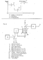
- Fig. 1 shows such a picture with some typical substances, where curve A is hydrogen, curve B is methane, curve C is carbon monoxide. If these results are evaluated in a microprocessor, to which the assignment of the sensor output signals and the temperature is transmitted, a three-dimensional matrix results, which is shown in FIG. 2.
- A is the sensor output signal
- B the sensor temperature and C a correction factor in order to be able to dimension the sensor output signal for specific substances, e.g. B. in ppm.
- each substance is "taken a fingerprint once" and stored as a number in the computer program. With the help of this method, numerous substances can be clearly identified.
- the device including the sensor is advantageously calibrated once with measuring gases, the specific correction numbers and identification numbers being stored in a non-volatile memory of the device. This process, which can be called “self-learning calibration and identification”, is advantageously carried out before the device is delivered to the customer.
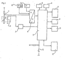
- a semiconductor sensor element is connected in series with a resistor and forms an electrical voltage divider (1).
- the sensor element is heated by a heating device (3) which is fed by a controlled current source (2).
- the power source is program controlled by a microprocessor (7).
- the temperature (13) and the relative humidity (14) are read into the microprocessor (7) via an analog / digital converter (4) using suitable, technically known sensors. These can be shown on a display (8), the quantity and the quality of the detected substance being shown according to the invention.
- a protocol interface is provided, which is designed as a conventional computer interface.
- An alarm output (10) is provided in order to give an acoustic and / or visual alarm if freely defined danger values are exceeded.
- a keyboard is temporarily connected via a suitable, technically known interface, in order to be able to control the "learning process” and to define the group of substances that will later be shown in the display.
- the resulting identification and correction data are stored in a non-volatile memory (6), e.g. B. an EEPROM.
- the functionality of the battery can be checked via a test switch (12) and other relevant functions can be checked automatically.
- this device thus represents an inexpensive, easy-to-use and robust device which is not only able to detect the presence of any substances, but at the same time can make a statement as to which group of substances the substance is to be assigned and which concentration is present.
- the disadvantage is that at relatively low working temperatures, as are typical for some substances, the regeneration after exposure to the substances in particular is sometimes impermissibly long.
- the sensor temperature is periodically brought to a relatively high level, which, however, does not destroy the sensor element. During this period, the sensor element surface is reoxidized by reaction with the atmospheric oxygen. After this period, the sensor element temperature is brought to a level that corresponds to the highest sensitivity to a certain substance.
- the output value of the sensor cannot yet be used for measurement purposes because an equilibrium state must first be reached on the surface. After reaching equilibrium, measurements can be carried out in a stable and reproducible manner.
- the duration of the preparation phase T1 and the measurement phase T2 depend on the respective sensor type and on the conditions under which the sensor is used.
- the measured gas-dependent voltage (5) hereinafter referred to as sensor voltage, determined according to one of the previously described methods, is supplied to suitable evaluation electronics (13) which trigger an output signal (14).
- the energy required to operate the heating element (11) is made available by a control module (6).
- the heating power is solely a function of the heating voltage or the heating current, without a real control loop being created by temperature comparison.
- a reference value can be supplied via input (7), which influences the heating power / heating voltage. If the sensor element is operated under changing ambient temperatures, it makes sense to record the real sensor element temperature and process it as the actual variable in the controller (6).
- Switching takes place either manually and once or automatically and time-controlled by a time clock (15).
- this temperature is relatively low, e.g. B. 250 C.
- the sensor element requires an extremely long time after the disappearance of the oxidizable substance, in the example carbon monoxide, in order to form tin dioxide again with the atmospheric oxygen.
- the recovery behavior of the sensor element becomes extremely sluggish at low sensor temperatures, so that the measurement results cannot be used for a long time.
- the sensor element is operated at a temperature T 1 at which an optimal reaction with the atmospheric oxygen takes place.
- T 1 A defined initial state is achieved by oxidation of the sensor element surface.
- the heating temperature is switched to a lower temperature T 2, which corresponds to the optimum reaction temperature of the substance sought.
- the measured value (14) can be obtained and processed.
- a switch is made to a higher regeneration phase T 3 (heating phase), which can be equal to or higher than T 1.
- the sensor element is advantageously operated in the measuring phase in a temperature range in which it is particularly sensitive to very specific gases.
- the regeneration of the sensor element is accelerated by the periodic operation at temperatures at which the regeneration or oxidation of the sensor element surface takes place particularly quickly.
- a set specific sensitivity is therefore advantageously achieved quickly without the sensor element having to recover particularly slowly.
- metal oxide gas sensors have a significantly different sensitivity to specific gases at different temperatures.
- the explanation for this is that at certain temperatures the reactivity of the metal oxide and in this respect the readiness for oxidation of the specific gas is, among other things, a function of the surface temperature of the metal oxide.
- the solution takes advantage of the fact that the electrical resistance of a heating element is generally temperature-dependent, the majority of which has a positive temperature coefficient.
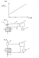
- Fig. 6 z. B the typical behavior of a platinum heater is shown, the electrical resistance of the heating element increases with increasing temperature of the heating element.
- the function between temperature and resistance can be defined.
- the temperature of the heating element is directly related to the temperature of the sensor element.
- the solution according to the invention consists in achieving reproducible temperature stabilization in that the heating resistance relevant to the desired temperature of the sensor is found and maintained.
- the teaching of the invention is therefore to design the heating of the sensor element so that the electrical resistance of the heating element serves as the actual variable.
- FIG. 7 A variant approaching the solution according to the invention is described in FIG. 7.
- the sensor element (3) is heated by a heating element (2), the thermal coupling between the heating element and the sensor element being very tight, so that both temperatures are almost identical.
- the power supply takes place e.g. B. from a controlled constant current source (1).
- the heating voltage (5) resulting from the current at the heating element is fed to a controller, which is preferably represented by a microprocessor (6).
- the microprocessor controller receives the desired size either program-controlled or set externally via a preselection device (7).
- the microprocessor controller (6) controls a constant voltage source (10).
- This voltage source drives a current through the heating element (2) and through a series resistor (9).
- a voltage (8) is tapped at the series resistor, which corresponds to the current due to the known laws.
- the current through the resistor (9) is inevitably identical to the current through the heating element (2).
- the total resistance flowing through the heating element (2) and the resistor (9) can easily be calculated.
- the known resistance value (9) the size of the ohmic resistance of the heating element (2) is calculated.
- the further embodiment corresponds to the teaching described above. It is important that the heating power is based on a predetermined resistance value of the heating element (2), the temperature-dependent values of which are used as the target value.
- a heating structure is applied to the ceramic substrate, which is preferably metallic.
- the object of the solution described below is to simplify the manufacturing process and to significantly reduce the tolerances by using processes known per se in semiconductor technology.
- the sensor carrier is made of silicon. Through the use of polycrystalline silicon, it is easily possible to form any desired shape and size of an ohmic heater with this carrier material.
- polycrystalline silicon When using polycrystalline silicon and appropriate contacting, it is possible to add a non-metallic electrical conductor to the carrier as a heater.
- a non-metallic electrical conductor As is known, polycrystalline silicon is electrically conductive and therefore heats up when a voltage is applied.
- FIGS. 9 and 10 show a heating element (1) which is electrically connected via the contacts (2) and operated via the voltage supply (3).
- This heating element (1) is now further processed according to the methods known in semiconductor technology and first receives an insulation layer (4) made of z. B. silicon dioxide.
- the thin-film elements are supported by a silicon substrate (5).
- a photosensitive layer is now applied, which contains the structures of the actual sensor element. Any desired structural shape can be produced.
- the senor base material After exposure, the sensor base material is applied. It is obvious that the accuracies that can be achieved with this method are considerably superior to those of conventional thick-film technology and therefore produce more uniform results.
- this process can be repeated any number of times, with different sensor materials being applied in the individual work steps, so that, for. B. the sensor elements (6), (7), (8).
- a temperature sensor element (9) can be applied at a location representative of the temperature, which is made of an electrically conductive and highly temperature-resistant material, e.g. B. made of platinum.
- FIG. 9 shows the basic structure in a sectional view
- FIG. 10 shows the basic structure in plan view.
- a catalyst layer made of a catalytically active metal such as. B. vaporize palladium, platinum, rodium, etc., or to apply in a suitable form, this layer being made gas-permeable.
- the applied layer is so thin that gas atoms can easily diffuse through it. It is also proposed that the catalyst layer be porous, e.g. B. in the form of a network structure.
- each individual sensor element being specifically sensitive to different gases.
- the sensitivity to individual gases can be significantly increased or even selectivity achieved by using suitable evaluation methods.
- heated sensor elements made of metal oxides or similar materials change their internal resistance when oxidizable or reducing gases are present.
- Usual evaluation circuits therefore work with a voltage divider, which is formed from an ohmic resistor and the sensor.
- the divider voltage resulting in the voltage divider is a function of the gas concentration.
- the senor is not flowed through with direct current, but with alternating voltage.
- Fig. 12 shows a diagram which shows the dependence of the sensor resistance for a given gas concentration on the frequency. Since the differences in the individual gases are significant, it is proposed to use this effect to increase the selectivity.
- the temperature is permanently changed between a maximum and minimum temperature by a computer for evaluation.
- the resulting data is saved and used to identify the gas.
- the sensor voltage typically changes with the frequency for certain gases.
- the sensor voltage is therefore read in by the microprocessor and stored during the learning process in a matrix which is located in the memory module (9 FIG. 11).
- the program of the microprocessor is written in such a way that the resulting sensitivity curves are always compared with the "learned" curves during later normal operation. In this respect, it is possible not only to make the sensor sensitive to certain gases by setting it to a certain frequency, but also to once again identify "learned" gases.
- the senor with a semiconductor sensor element which is applied to an electrically and thermally insulating support and is heated to an operating temperature by means of an electrical heater, is constructed in such a way that the semiconductor sensor element itself is designed as a heater.
- the advantageous integration of the heater in the semiconductor sensor element means that the previous separate heater can be dispensed with, so that the sensor as a whole can be manufactured much more cost-effectively.
- the desired operating temperature is kept constant in a simple manner, in order to use the reaction heat or temperature difference or change in conductivity of the sensor element as a measured variable for the gases to be detected when reacting with the gases surrounding the sensor.
- an evaluation unit is connected between the sensor element and the power controller via a circuit branch, which can be designed as a microprocessor.
- FIG. 13 shows a sensor with a power controller, an evaluation unit and a sensor element
- FIG. 16 shows a sectional illustration of the sensor element according to FIG. 14.
- the sensor element (14) shown in FIGS. 15 and 16 consists of a carrier 18 which, for. B. consists of an oxide ceramic 8, for example made of A1 2 0 3 or polycrystalline silicon with an electrically neutral insulating cover layer made of Si0 2 , on which a sensor element (14) designed as a semiconductor (32) is applied.
- the semiconductor (32) can, for example, be sintered onto the carrier. Another production possibility would be to apply the semiconductor (32) to the surface of the carrier (18) using thick-film technology.
- the semiconductor (32) consists of catalytically admixed and electrically conductive metal oxide, tin dioxide (Sn0 2 ) being used in an advantageous manner.
- the power regulator (12) shown in FIG. 13 and the sensor element (14) are connected to a current source (22) via the electrical connections (20) and (28).
- the power controller (12) is also connected to the sensor element (14) via an electrical connection (24) (16) to the electrical connection (24) and thus to the power controller and the sensor element (14).
- the gases can be detected in a simple manner.
- a voltage is applied to the sensor element (14), so that the current flow caused thereby inevitably results in the sensor element (14) being heated.
- the heating depends on the resistance of the sensor element (14) and on the applied voltage.
- the converted power is calculated with the heating voltage using the formulas
- the heating voltage U must therefore change as a function of the resistance R of the sensor element (14) and thus as a function of the gases surrounding the sensor element (14) so that the heating power P becomes constant. If the heating power P were not regulated, the heating power P would change depending on the resistance R.
- the power regulator (12) ensures that the product of current I and voltage U, that is to say the electrical power P, remains constant.
- the electrical power P is converted in the sensor element (14).
- the necessary voltage U applied to the sensor element (14) is constantly adapted by the power controller (12), the voltage U regularly decreasing when the sensor resistance R becomes smaller due to the presence of a gas and the power controller (12) reacts accordingly. It follows that the sensor voltage at the sensor element is a function of the gas concentration and can be evaluated in the evaluation unit (16).
- the power controller can be designed as a separate assembly. It is particularly advantageous if the power control is carried out by a microprocessor simultaneously with the signal evaluation, the microprocessor, which can be integrated in the evaluation unit (16), only has to measure the current. A further microprocessor is provided in the power controller (12), which processes the corresponding disturbance variables and ensures that the product of voltage U and current I, that is to say the power P, is kept constant.
- the power regulator (12) can also be designed as a controlled constant current source.
- the evaluation unit (16) which controls the constant current source via the connection (30).
Landscapes
- Chemical & Material Sciences (AREA)
- Chemical Kinetics & Catalysis (AREA)
- Electrochemistry (AREA)
- Physics & Mathematics (AREA)
- Health & Medical Sciences (AREA)
- Life Sciences & Earth Sciences (AREA)
- Analytical Chemistry (AREA)
- Biochemistry (AREA)
- General Health & Medical Sciences (AREA)
- General Physics & Mathematics (AREA)
- Immunology (AREA)
- Pathology (AREA)
- Investigating Or Analysing Materials By Optical Means (AREA)
- Investigating Or Analyzing Materials By The Use Of Fluid Adsorption Or Reactions (AREA)
Applications Claiming Priority (12)
| Application Number | Priority Date | Filing Date | Title |
|---|---|---|---|
| DE3827426 | 1988-08-12 | ||
| DE19883827426 DE3827426A1 (de) | 1988-08-12 | 1988-08-12 | Vorrichtung zur durchfuehrung eines verfahrens zum zwecke der identifizierung und quantifizierung unbekannter gasfoermiger substanzen |
| DE3905993 | 1989-02-25 | ||
| DE19893905993 DE3905993A1 (de) | 1989-02-25 | 1989-02-25 | Apparat und verfahren zum zwecke der detektierung oxidierbarer und/oder reduzierbarer gase |
| DE3907556 | 1989-03-09 | ||
| DE19893907556 DE3907556A1 (de) | 1989-03-09 | 1989-03-09 | Apparat und verfahren zur erhoehung der selektivitaet von halbleitersensoren durch geregelte heiztemperatur |
| DE3917519 | 1989-05-30 | ||
| DE19893917519 DE3917519A1 (de) | 1989-05-30 | 1989-05-30 | In duennfilmtechnik auf siliziumsubstrat aufgebrachter multisensor zur detektion von gasen |
| DE19893917853 DE3917853A1 (de) | 1989-06-01 | 1989-06-01 | Gasempfindlicher halbleitersensor mit frequenzabhaengig veraenderter selektivitaet |
| DE3917853 | 1989-06-01 | ||
| DE19893918684 DE3918684A1 (de) | 1989-06-08 | 1989-06-08 | Senor mit einem halbleitersensorelement |
| DE3918684 | 1989-06-08 |
Publications (2)
| Publication Number | Publication Date |
|---|---|
| EP0354486A2 true EP0354486A2 (fr) | 1990-02-14 |
| EP0354486A3 EP0354486A3 (fr) | 1990-08-01 |
Family
ID=27544514
Family Applications (1)
| Application Number | Title | Priority Date | Filing Date |
|---|---|---|---|
| EP89114409A Withdrawn EP0354486A3 (fr) | 1988-08-12 | 1989-08-04 | Appareil pour utiliser un procédé dans le but d'identifier et de quantifier des substances gazeuses inconnues |
Country Status (1)
| Country | Link |
|---|---|
| EP (1) | EP0354486A3 (fr) |
Cited By (8)
| Publication number | Priority date | Publication date | Assignee | Title |
|---|---|---|---|---|
| RU2124719C1 (ru) * | 1997-11-12 | 1999-01-10 | Вологодский Политехнический Институт | Устройство для измерения концентрации аммиака |
| DE4111113C2 (de) * | 1991-04-03 | 2000-09-21 | Itvi Inttech Venture Investa | Phthalocyanin-Sensor zum Zwecke des Nachweises von Stickoxiden in der Luft |
| DE4037479C2 (de) * | 1990-11-24 | 2002-04-11 | Paragon Ag | Phthalocyanin-Sensor zum Zwecke des Nachweises von Stickoxyden in der Luft |
| CN1311236C (zh) * | 2000-10-16 | 2007-04-18 | 纳幕尔杜邦公司 | 分析气体混合物的方法和设备 |
| EP1602924A3 (fr) * | 2004-06-03 | 2007-09-19 | UST Umweltsensortechnik GmbH | Dispositif et procédé pour detecter des composés organiques volatiles |
| US7737700B2 (en) | 2005-11-23 | 2010-06-15 | Ust Umweltsensortechnik Gmbh | Arrangement and method for detecting air ingredients |
| CN115622551A (zh) * | 2021-07-16 | 2023-01-17 | 长鑫存储技术有限公司 | 半导体器件、电阻开关及其制作方法 |
| DE102023201750A1 (de) | 2023-02-27 | 2024-08-29 | Robert Bosch Gesellschaft mit beschränkter Haftung | Verfahren zum Betreiben eines Halbleitergassensors und Halbleitergassensor |
Family Cites Families (4)
| Publication number | Priority date | Publication date | Assignee | Title |
|---|---|---|---|---|
| NL7908932A (nl) * | 1979-03-07 | 1980-09-09 | Draegerwerk Ag | Halfgeleider-gassensor met geregelde verwarming. |
| JPS57189289A (en) * | 1981-05-15 | 1982-11-20 | Toubishi Kogyo Kk | Gas detection monitor |
| EP0092068B1 (fr) * | 1982-04-15 | 1986-06-11 | Cerberus Ag | Dispositif d'alarme pour gaz et/ou vapeurs |
| US4542640A (en) * | 1983-09-15 | 1985-09-24 | Clifford Paul K | Selective gas detection and measurement system |
-
1989
- 1989-08-04 EP EP89114409A patent/EP0354486A3/fr not_active Withdrawn
Cited By (8)
| Publication number | Priority date | Publication date | Assignee | Title |
|---|---|---|---|---|
| DE4037479C2 (de) * | 1990-11-24 | 2002-04-11 | Paragon Ag | Phthalocyanin-Sensor zum Zwecke des Nachweises von Stickoxyden in der Luft |
| DE4111113C2 (de) * | 1991-04-03 | 2000-09-21 | Itvi Inttech Venture Investa | Phthalocyanin-Sensor zum Zwecke des Nachweises von Stickoxiden in der Luft |
| RU2124719C1 (ru) * | 1997-11-12 | 1999-01-10 | Вологодский Политехнический Институт | Устройство для измерения концентрации аммиака |
| CN1311236C (zh) * | 2000-10-16 | 2007-04-18 | 纳幕尔杜邦公司 | 分析气体混合物的方法和设备 |
| EP1602924A3 (fr) * | 2004-06-03 | 2007-09-19 | UST Umweltsensortechnik GmbH | Dispositif et procédé pour detecter des composés organiques volatiles |
| US7737700B2 (en) | 2005-11-23 | 2010-06-15 | Ust Umweltsensortechnik Gmbh | Arrangement and method for detecting air ingredients |
| CN115622551A (zh) * | 2021-07-16 | 2023-01-17 | 长鑫存储技术有限公司 | 半导体器件、电阻开关及其制作方法 |
| DE102023201750A1 (de) | 2023-02-27 | 2024-08-29 | Robert Bosch Gesellschaft mit beschränkter Haftung | Verfahren zum Betreiben eines Halbleitergassensors und Halbleitergassensor |
Also Published As
| Publication number | Publication date |
|---|---|
| EP0354486A3 (fr) | 1990-08-01 |
Similar Documents
| Publication | Publication Date | Title |
|---|---|---|
| DE3711511C1 (de) | Verfahren zur Bestimmung der Gaskonzentrationen in einem Gasgemisch und Sensor zur Messung der Waermeleitfaehigkeit | |
| DE69516274T2 (de) | Feuchtigkeitssensor | |
| US5345213A (en) | Temperature-controlled, micromachined arrays for chemical sensor fabrication and operation | |
| DE69514106T2 (de) | Resistiver gassensor insbesondere zur detektion von ozon | |
| DE69123377T2 (de) | Gassensoren zur Bestimmung von gasförmigen Kohlenwasserstoffen unter Verwendung von dünnen Zinnoxidschichten | |
| DD283866A5 (de) | Verfahren zur bestimmung und vorrichtung zum messen der waermeleitfaehigkeit von materialien | |
| WO1994010559A9 (fr) | Ensembles micro-usines a temperature controlee utilises pour la fabrication et l'utilisation de capteurs chimiques | |
| DE3921526A1 (de) | Diffusionsbarriere mit temperaturfuehler fuer einen elektrochemischen gassensor | |
| DE102018122860A1 (de) | Verfahren zum Betreiben einer Sensorvorrichtung | |
| EP0464244B1 (fr) | Capteur pour la détection de gaz réducteurs | |
| EP0801302A1 (fr) | Méthode pour déterminer l'humidité absolue de l'air | |
| DE4109516C2 (de) | Vorrichtung zum kontinuierlichen Überwachen der Konzentrationen von gasförmigen Bestandteilen in Gasgemischen | |
| EP3729009B1 (fr) | Capteur d'écoulement thermique servant à définir la température et la vitesse d'écoulement d'un milieu de mesure s'écoulant | |
| DE4139721C1 (en) | Simple compact gas detector for selective detection - comprise support, gallium oxide semiconducting layer, contact electrode, temp. gauge, heating and cooling elements | |
| Mielle | Managing dynamic thermal exchanges in commercial semiconduting gas sensors | |
| EP0522118B1 (fr) | Dispositif de controle en continu de la concentration en constituants gazeux de melanges gazeux | |
| DE10003676B4 (de) | Verfahren und Vorrichtung zur Bestimmung der Konzentrationen eines H2/He-Gasgemisches | |
| DE102020134064A1 (de) | Gassensor | |
| DE69806375T2 (de) | Verfahren und apparat zum messen von enthalpieänderungen mittels eines mit quasi-isothermem heizverfahren arbeitenden differentialthermoanalyseapparates (dta-apparat) | |
| DE102013206637A1 (de) | Verfahren zum Analysieren eines Gases | |
| DE102022116825A1 (de) | Sensor-Anordnung mit einem elektrochemischen Sensor und einem Temperatur-Sensor und Verfahren unter Verwendung einer solchen Sensor-Anordnung | |
| DE102018108723A1 (de) | Sensorvorrichtung, Verfahren zum Betreiben einer Sensorvorrichtung und elektronische Baugruppe, die eine Sensorvorrichtung aufweist | |
| DE10019010B4 (de) | Verwendung eines chemisch sensitiven Halbleitermaterials zum Nachweis von gas- und/oder dampfförmigen Analyten in Gasen | |
| DE4226591C1 (en) | Gas sensor with temp. regulation circuit including resistance bridge - has control circuit for maintaining temp. of sensors in resistance bridge circuit constant, with circuit output indicating heat caused by gas | |
| DE60033036T2 (de) | Gassensor |
Legal Events
| Date | Code | Title | Description |
|---|---|---|---|
| PUAI | Public reference made under article 153(3) epc to a published international application that has entered the european phase |
Free format text: ORIGINAL CODE: 0009012 |
|
| AK | Designated contracting states |
Kind code of ref document: A2 Designated state(s): AT BE CH DE ES FR GB GR IT LI LU NL SE |
|
| PUAL | Search report despatched |
Free format text: ORIGINAL CODE: 0009013 |
|
| AK | Designated contracting states |
Kind code of ref document: A3 Designated state(s): AT BE CH DE ES FR GB GR IT LI LU NL SE |
|
| 17P | Request for examination filed |
Effective date: 19900814 |
|
| 17Q | First examination report despatched |
Effective date: 19920219 |
|
| STAA | Information on the status of an ep patent application or granted ep patent |
Free format text: STATUS: THE APPLICATION IS DEEMED TO BE WITHDRAWN |
|
| 18D | Application deemed to be withdrawn |
Effective date: 19920630 |