EP0354506A1 - Echangeur de chaleur pour fonctionner soit dans le mode "sec", soit dans le mode "humide" - Google Patents
Echangeur de chaleur pour fonctionner soit dans le mode "sec", soit dans le mode "humide" Download PDFInfo
- Publication number
- EP0354506A1 EP0354506A1 EP89114511A EP89114511A EP0354506A1 EP 0354506 A1 EP0354506 A1 EP 0354506A1 EP 89114511 A EP89114511 A EP 89114511A EP 89114511 A EP89114511 A EP 89114511A EP 0354506 A1 EP0354506 A1 EP 0354506A1
- Authority
- EP
- European Patent Office
- Prior art keywords
- heat exchanger
- water
- tubes
- air
- pipes
- Prior art date
- Legal status (The legal status is an assumption and is not a legal conclusion. Google has not performed a legal analysis and makes no representation as to the accuracy of the status listed.)
- Granted
Links
- XLYOFNOQVPJJNP-UHFFFAOYSA-N water Substances O XLYOFNOQVPJJNP-UHFFFAOYSA-N 0.000 claims abstract description 63
- 238000001816 cooling Methods 0.000 claims abstract description 40
- 239000012530 fluid Substances 0.000 claims description 11
- 238000000034 method Methods 0.000 claims description 7
- 238000001035 drying Methods 0.000 claims description 2
- 230000009969 flowable effect Effects 0.000 claims description 2
- 230000001105 regulatory effect Effects 0.000 claims description 2
- 239000003570 air Substances 0.000 description 29
- 239000012080 ambient air Substances 0.000 description 6
- 230000015572 biosynthetic process Effects 0.000 description 6
- 239000007921 spray Substances 0.000 description 3
- 239000004033 plastic Substances 0.000 description 2
- 229920003023 plastic Polymers 0.000 description 2
- 239000004721 Polyphenylene oxide Substances 0.000 description 1
- 239000004743 Polypropylene Substances 0.000 description 1
- 239000004793 Polystyrene Substances 0.000 description 1
- 238000010521 absorption reaction Methods 0.000 description 1
- 229920000122 acrylonitrile butadiene styrene Polymers 0.000 description 1
- 239000004676 acrylonitrile butadiene styrene Substances 0.000 description 1
- 239000011324 bead Substances 0.000 description 1
- 230000001427 coherent effect Effects 0.000 description 1
- 238000010276 construction Methods 0.000 description 1
- 239000000498 cooling water Substances 0.000 description 1
- 230000007423 decrease Effects 0.000 description 1
- 238000010586 diagram Methods 0.000 description 1
- 230000000694 effects Effects 0.000 description 1
- 230000002349 favourable effect Effects 0.000 description 1
- 239000013505 freshwater Substances 0.000 description 1
- 238000009434 installation Methods 0.000 description 1
- 239000007788 liquid Substances 0.000 description 1
- 238000004519 manufacturing process Methods 0.000 description 1
- 238000011089 mechanical engineering Methods 0.000 description 1
- 239000003595 mist Substances 0.000 description 1
- 239000000203 mixture Substances 0.000 description 1
- 238000012856 packing Methods 0.000 description 1
- 230000002093 peripheral effect Effects 0.000 description 1
- 229920001643 poly(ether ketone) Polymers 0.000 description 1
- 229920002492 poly(sulfone) Polymers 0.000 description 1
- 229920000515 polycarbonate Polymers 0.000 description 1
- 239000004417 polycarbonate Substances 0.000 description 1
- 229920006380 polyphenylene oxide Polymers 0.000 description 1
- -1 polypropylene Polymers 0.000 description 1
- 229920001155 polypropylene Polymers 0.000 description 1
- 229920002223 polystyrene Polymers 0.000 description 1
- 229920000915 polyvinyl chloride Polymers 0.000 description 1
- 239000004800 polyvinyl chloride Substances 0.000 description 1
- 238000009423 ventilation Methods 0.000 description 1
- 238000003466 welding Methods 0.000 description 1
Images

Classifications
-
- F—MECHANICAL ENGINEERING; LIGHTING; HEATING; WEAPONS; BLASTING
- F28—HEAT EXCHANGE IN GENERAL
- F28C—HEAT-EXCHANGE APPARATUS, NOT PROVIDED FOR IN ANOTHER SUBCLASS, IN WHICH THE HEAT-EXCHANGE MEDIA COME INTO DIRECT CONTACT WITHOUT CHEMICAL INTERACTION
- F28C1/00—Direct-contact trickle coolers, e.g. cooling towers
- F28C1/14—Direct-contact trickle coolers, e.g. cooling towers comprising also a non-direct contact heat exchange
-
- F—MECHANICAL ENGINEERING; LIGHTING; HEATING; WEAPONS; BLASTING
- F28—HEAT EXCHANGE IN GENERAL
- F28C—HEAT-EXCHANGE APPARATUS, NOT PROVIDED FOR IN ANOTHER SUBCLASS, IN WHICH THE HEAT-EXCHANGE MEDIA COME INTO DIRECT CONTACT WITHOUT CHEMICAL INTERACTION
- F28C1/00—Direct-contact trickle coolers, e.g. cooling towers
- F28C1/14—Direct-contact trickle coolers, e.g. cooling towers comprising also a non-direct contact heat exchange
- F28C2001/145—Direct-contact trickle coolers, e.g. cooling towers comprising also a non-direct contact heat exchange with arrangements of adjacent wet and dry passages
-
- Y—GENERAL TAGGING OF NEW TECHNOLOGICAL DEVELOPMENTS; GENERAL TAGGING OF CROSS-SECTIONAL TECHNOLOGIES SPANNING OVER SEVERAL SECTIONS OF THE IPC; TECHNICAL SUBJECTS COVERED BY FORMER USPC CROSS-REFERENCE ART COLLECTIONS [XRACs] AND DIGESTS
- Y02—TECHNOLOGIES OR APPLICATIONS FOR MITIGATION OR ADAPTATION AGAINST CLIMATE CHANGE
- Y02B—CLIMATE CHANGE MITIGATION TECHNOLOGIES RELATED TO BUILDINGS, e.g. HOUSING, HOUSE APPLIANCES OR RELATED END-USER APPLICATIONS
- Y02B30/00—Energy efficient heating, ventilation or air conditioning [HVAC]
- Y02B30/70—Efficient control or regulation technologies, e.g. for control of refrigerant flow, motor or heating
Definitions
- the invention relates to a heat exchanger for optional wet and dry operation, in particular for use in hybrid cooling towers.
- Wet cooling towers have the disadvantage that emerging steam vapors in the form of fog and black ice form a burden on the environment.
- dry cooling towers were built in which the water to be cooled releases heat energy only through heat exchange with the air, but not through evaporative cooling. As a result, their efficiency, based on the air flowing through them, is lower and a correspondingly larger dimensioning is required.
- hybrid cooling towers They therefore contain a part designed for pure wet cooling and a part designed for pure dry cooling, which are coordinated with one another in such a way that the undesirable formation of steam is avoided even under unfavorable temperature and humidity values.
- the increase in efficiency compared to pure dry cooling towers is limited by this condition.
- the invention relates to a heat exchanger for optional wet and dry operation, comprising at least one heat exchanger body with a multiplicity of pipes through which flow can flow in parallel and which open in two opposite planes, and with interspaces that can be flowed through in a cross-flow manner, characterized by a water inlet system for introducing drop-shaped water in at least part of the pipes and at least one actuator for regulating or shutting off the water distributed by the water inlet system.
- the invention further consists in a method for cooling a fluid using the heat exchanger described, in which the fluid is passed through the spaces between the tubes and air through the tubes and by means of the water inlet system drop-shaped water is introduced into the tubes and the amount of water introduced is limited by the actuator according to the air humidity so that there are no or at most short-reaching swaths at the top of the cooling tower.
- the new heat exchanger is suitable for cooling flowing gaseous or preferably liquid fluids, especially in the temperature range from 20 to 100 ° C. Water is preferably cooled.
- the new heat exchanger is especially designed for use in a hybrid cooling tower and allows the ratio of wet operation to dry operation to be shifted according to the air humidity so that the highest possible degree of efficiency can be achieved at all times with steam-free operation. If the air humidity increases with the outside temperature remaining the same, wet operation is reduced in favor of dry operation and vice versa.
- the control is expediently effected in that the actuator is influenced by sensors for the position of the dew point and the temperature of the surrounding air.
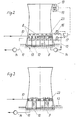
- the air flows through the pipes and the fluid to be cooled flows through the spaces 5 between the pipes.
- the pipes are usually arranged vertically and are flowed through from bottom to top by natural draft. If necessary, the natural draft can be supplemented or replaced by forced ventilation.
- the cooling capacity is limited to the heat transfer from the fluid to be cooled via the pipe wall to the flowing air.
- the main innovation of the invention is that the same heat exchanger elements can also be operated at least in part wet.
- water which is distributed in drops is introduced into at least some of the pipes by means of the water inlet system.
- the water is preferably sprayed onto the inner walls of the tubes by spray nozzles 6, which are attached in front of the entrances or the mouths of the tubes, and these are wetted with water.
- the arrangement of the spray nozzles 6 below the heat exchanger has the advantage that the spray mist is conveyed into the tubes with the inflowing air.
- the arrangement of the water inlet system above the heat exchanger makes sense if only part of the water distributed in drops is evaporated and a substantial part flows off at the bottom of the heat exchanger. It is not necessary to place a nozzle at every pipe mouth. As a rule, the water can be distributed from a suitable distance to the mouths of, for example, 7 to 20 pipes or more.
- the water which is distributed in drops, can evaporate more or less strongly in the flowing air, thereby reducing the temperature of the air. This increases their cooling capacity and, at the same time, the efficiency of the cooling system. As far as the inner walls of the pipes are wetted by the water, it evaporates from there and causes an immediate cooling of the pipes.
- a hybrid cooling tower equipped with heat exchangers according to the invention is operated as a function of the air humidity, ie of the temperature of the surrounding air and its dew point.
- the temperature increases as it passes through the cooling tower, increasing the distance from the dew point.
- the temperature also increases, but the distance to the dew point decreases due to the moisture absorption.
- the moist exhaust air emerges at the head of the cooling tower and mixes with the cooler ambient air. The dew point can be reached or fallen below, so that the undesirable formation of steam occurs.
- the vapors dissolve again when mixed with the ambient air. It is an object of the invention to limit the volume of the ambient air with which the exhaust air must be mixed until the swaths are dissolved, so that short-reaching swaths occur at the top of the cooling tower.
- Humidity of the ambient air reduces the supply of the drop-shaped water in the tubes of the heat exchanger or vice versa as the rel. Humidity increases the water supply. This is most conveniently done by reducing or increasing the proportion of the heat exchanger surface that works in wet operation.
- the distance between the temperature of the exhaust air and the temperature of the ambient air is also very important.
- the invention makes it possible to coordinate the ratio of simultaneous wet and dry operation to one another in such a way that the greatest possible cooling capacity is achieved with minimal swath formation, taking into account the criteria listed.
- this adjustment can be done empirically by increasing the water supply until a just permissible vapor formation occurs.
- the voting is preferably carried out automatically.
- the rel. Air humidity and the temperature of the outside air are determined by known suitable sensors 18 and the measured values are fed to a control unit 17 which regulates the water supply by means of the actuators 16 in the water pipe system in such a way that according to the hx diagram for air according to Mollier (cf. Dubbels Paperback for mechanical engineering, publisher Saas, Couché, Leitner, 13th edition 1974, p. 462, picture 15) a largely swath-free operation is guaranteed.
- the actuator can have the effect of throttling the water supply to the nozzles 6 or to a part of them, so that more or less water enters the pipes concerned in accordance with the required operating state.
- the water supply to a variable part of the pipes is shut off by the actuator, so that each pipe is operated either dry or wet.
- the water supply to individual nozzles 6 or groups of nozzles 6 is expediently opened or closed as required. Accordingly, water is introduced into a part of the pipes or a part of the heat exchanger bodies, which together form the heat exchanger according to the invention, and the water supply to the remaining part is interrupted.
- the dry and wet areas are divided into many small islands arranged in a mixed manner, for example the size of one or more heat exchanger bodies.
- a dry operating zone is firmly arranged in a ring around a central wet operating zone.
- the moist exhaust air from the wet zone is mixed inside the cooling tower often only imperfectly with the dry exhaust air from the peripheral zone and still forms far-reaching vapors if the proportion of the dry exhaust air had been sufficient to suppress the formation of vapors with uniform mixing.
- the tubes 1 have a circular cross-section and, at intervals along their length, inwardly directed beads 2 for swirling the air flowing therein. At their ends 3, 3 ', the tubes 1 are expanded in a hexagonal shape and connected to one another in this area to form a hexagonal honeycomb pattern. The tubes 1 thus open in levels 4, 4 '.
- the pipe diameters d are generally more than 75%, preferably more than 90% of the distances a between the pipe axes of adjacent pipes 1.
- the pipe cross sections then make up more than 50 and preferably 75 to 90% of the total cross-sectional area of the heat exchanger body; this means the area enclosed by the sheathing.
- the remaining part of the cross-sectional area ie less than 50%, preferably 10 to 25% of the cross-sectional area, form gaps 5 through which the fluid to be cooled can flow crosswise to the tubes 1.
- the tubes preferably have an inside diameter of 10 to 100 mm and a length of 0.5 to 2 m. 200 to 20,000 pipes are welded to heat exchanger bodies with a circumferential installation flange 7.
- the design described with hexagonally widened and interconnected pipe ends 3 permits tight packing of the pipes 1 that is optimal for heat exchange.
- They are preferably made of plastic and are welded together in the area of the pipe ends 3.
- Methods for welding tube bundles into coherent heat exchanger bodies are known from DE-A 35 22 190.
- Flanges can be attached according to DE-A 38 13 882 (currently not yet published).
- Suitable plastics are those which are sufficiently resistant to water and the fluid to be cooled, which is preferably also water, at the highest possible operating temperatures which occur at the point of entry of the fluid to be cooled into the heat exchanger. Examples include polypropylene, polyvinyl chloride, polystyrene or ABS, polycarbonate, polysulfone, polyphenylene oxide, polyether ketones, etc. called.
- a plurality of heat exchanger bodies with, for example, a rectangular plan by means of mounting flanges 7, 7 'to form a large-area heat exchanger plane 23, which essentially fills the cross section of the hybrid cooling tower, or to form several such planes and together with the water inlet system on one Support frame 9.
- pipelines 10, 11 are provided which lead to the intermediate spaces 5.
- Another component of an expedient embodiment of a hybrid cooling tower is a collecting pond 12 for the water dripping from the heat exchangers 1.
- a fresh water line 13 can also open there. From the collecting pond 12, the water passes through a circulation pump 14 and a line 15 to the actuators.
- Valves 16 equipped with servomotors are suitable as such, the servomotors of which are driven by a control unit 17 in conjunction with sensors 18, 19 for the temperatures and dew points of the ambient and exhaust air.
- a plurality of such valves 16 are required in a hybrid cooling tower for a power plant block of customary size.
- a level 23 of heat exchangers according to the invention is wholly or partly designed in such a way that the water is first led in a dry process through a more or less large proportion of the heat exchanger bodies and then on a more or less large proportion of the heat exchanger bodies as a wet part the inside of the pipes is diverted in direct connection with the air flowing through.
- the respective proportions depend on the temperature and the relative humidity of the surrounding air.
- the cooled flowing out of the pipes Water collects in the pond 12 located under the tower and is conveyed back from there via the circulation pump 14 and the line 15 to the heat source.
Landscapes
- Engineering & Computer Science (AREA)
- Mechanical Engineering (AREA)
- General Engineering & Computer Science (AREA)
- Heat-Exchange Devices With Radiators And Conduit Assemblies (AREA)
- Separation By Low-Temperature Treatments (AREA)
- Drying Of Gases (AREA)
- Power Steering Mechanism (AREA)
- Compression-Type Refrigeration Machines With Reversible Cycles (AREA)
- Devices For Blowing Cold Air, Devices For Blowing Warm Air, And Means For Preventing Water Condensation In Air Conditioning Units (AREA)
- Drying Of Solid Materials (AREA)
Priority Applications (1)
| Application Number | Priority Date | Filing Date | Title |
|---|---|---|---|
| AT89114511T ATE70625T1 (de) | 1988-08-10 | 1989-08-05 | Waermeaustauscher fuer wahlweisen nass- und trockenbetrieb. |
Applications Claiming Priority (2)
| Application Number | Priority Date | Filing Date | Title |
|---|---|---|---|
| DE8810151U DE8810151U1 (de) | 1988-08-10 | 1988-08-10 | Wärmeaustauscher für wahlweisen Naß- und Trockenbetrieb |
| DE8810151U | 1988-08-10 |
Publications (2)
| Publication Number | Publication Date |
|---|---|
| EP0354506A1 true EP0354506A1 (fr) | 1990-02-14 |
| EP0354506B1 EP0354506B1 (fr) | 1991-12-18 |
Family
ID=6826781
Family Applications (1)
| Application Number | Title | Priority Date | Filing Date |
|---|---|---|---|
| EP89114511A Expired - Lifetime EP0354506B1 (fr) | 1988-08-10 | 1989-08-05 | Echangeur de chaleur pour fonctionner soit dans le mode "sec", soit dans le mode "humide" |
Country Status (6)
| Country | Link |
|---|---|
| EP (1) | EP0354506B1 (fr) |
| JP (1) | JPH0282091A (fr) |
| AT (1) | ATE70625T1 (fr) |
| AU (1) | AU3949689A (fr) |
| DE (2) | DE8810151U1 (fr) |
| ZA (1) | ZA896122B (fr) |
Cited By (4)
| Publication number | Priority date | Publication date | Assignee | Title |
|---|---|---|---|---|
| WO1999030096A1 (fr) * | 1997-12-11 | 1999-06-17 | Gea Kühlturmbau Gmbh | Tour de refroidissement hybride |
| RU2153137C2 (ru) * | 1998-06-29 | 2000-07-20 | Прохоров Евгений Иванович | Градирня |
| US7864530B1 (en) * | 2007-09-28 | 2011-01-04 | Exaflop Llc | Changing data center cooling modes |
| US11890579B2 (en) | 2018-10-02 | 2024-02-06 | President And Fellows Of Harvard College | Hydrophobic barrier layer for ceramic indirect evaporative cooling systems |
Families Citing this family (1)
| Publication number | Priority date | Publication date | Assignee | Title |
|---|---|---|---|---|
| CN100398967C (zh) * | 2006-05-13 | 2008-07-02 | 山西鑫海源工贸有限公司 | 三相流化湍球冷却塔 |
Citations (4)
| Publication number | Priority date | Publication date | Assignee | Title |
|---|---|---|---|---|
| EP0010118A1 (fr) * | 1978-10-23 | 1980-04-30 | Hamon-Sobelco S.A. | Corps d'échange thermique, notamment pour réfrigérant atmosphérique |
| DE3135783A1 (de) * | 1981-09-10 | 1983-05-19 | Ekkehard Dipl.-Ing. 7302 Ostfildern Bretting | Kombinierter trocken- und nasskuehlturm |
| EP0151547A2 (fr) * | 1984-01-25 | 1985-08-14 | Electricite De France | Réfrigérant atmosphérique à panache réduit |
| EP0237486A1 (fr) * | 1986-03-08 | 1987-09-16 | Colenco AG | Elément de refroidissement |
-
1988
- 1988-08-10 DE DE8810151U patent/DE8810151U1/de not_active Expired - Lifetime
-
1989
- 1989-08-05 AT AT89114511T patent/ATE70625T1/de not_active IP Right Cessation
- 1989-08-05 DE DE8989114511T patent/DE58900584D1/de not_active Expired - Lifetime
- 1989-08-05 EP EP89114511A patent/EP0354506B1/fr not_active Expired - Lifetime
- 1989-08-10 ZA ZA896122A patent/ZA896122B/xx unknown
- 1989-08-10 AU AU39496/89A patent/AU3949689A/en not_active Abandoned
- 1989-08-10 JP JP1205844A patent/JPH0282091A/ja active Pending
Patent Citations (4)
| Publication number | Priority date | Publication date | Assignee | Title |
|---|---|---|---|---|
| EP0010118A1 (fr) * | 1978-10-23 | 1980-04-30 | Hamon-Sobelco S.A. | Corps d'échange thermique, notamment pour réfrigérant atmosphérique |
| DE3135783A1 (de) * | 1981-09-10 | 1983-05-19 | Ekkehard Dipl.-Ing. 7302 Ostfildern Bretting | Kombinierter trocken- und nasskuehlturm |
| EP0151547A2 (fr) * | 1984-01-25 | 1985-08-14 | Electricite De France | Réfrigérant atmosphérique à panache réduit |
| EP0237486A1 (fr) * | 1986-03-08 | 1987-09-16 | Colenco AG | Elément de refroidissement |
Cited By (5)
| Publication number | Priority date | Publication date | Assignee | Title |
|---|---|---|---|---|
| WO1999030096A1 (fr) * | 1997-12-11 | 1999-06-17 | Gea Kühlturmbau Gmbh | Tour de refroidissement hybride |
| RU2153137C2 (ru) * | 1998-06-29 | 2000-07-20 | Прохоров Евгений Иванович | Градирня |
| US7864530B1 (en) * | 2007-09-28 | 2011-01-04 | Exaflop Llc | Changing data center cooling modes |
| US8526183B1 (en) | 2007-09-28 | 2013-09-03 | Exaflop Llc | Data center cooling circulation |
| US11890579B2 (en) | 2018-10-02 | 2024-02-06 | President And Fellows Of Harvard College | Hydrophobic barrier layer for ceramic indirect evaporative cooling systems |
Also Published As
| Publication number | Publication date |
|---|---|
| AU3949689A (en) | 1990-02-15 |
| DE8810151U1 (de) | 1989-12-21 |
| ZA896122B (en) | 1990-05-30 |
| ATE70625T1 (de) | 1992-01-15 |
| DE58900584D1 (de) | 1992-01-30 |
| EP0354506B1 (fr) | 1991-12-18 |
| JPH0282091A (ja) | 1990-03-22 |
Similar Documents
| Publication | Publication Date | Title |
|---|---|---|
| DE2840317A1 (de) | Einrichtung bei einem verdunstungskuehler | |
| WO2013120600A2 (fr) | Dispositif de refroidissement ou de récupération de chaleur | |
| DE1551489A1 (de) | Waermeaustauscher | |
| DE2251709A1 (de) | Kondensationseinrichtung fuer dampfturbinenkraftwerke | |
| DE3007256A1 (de) | Zentralheizungs- und/oder warmwassererzeugungsanlage | |
| DE2452123B2 (de) | Kombinierter Naß-/Trockenkühlturm | |
| DE202025102233U1 (de) | Turm zur Abscheidung und Absorption von Kohlenstoff | |
| EP0148469A2 (fr) | Procédé et dispositif de séparation de gaz nocifs à partir de gaz de fumée | |
| WO2010139377A1 (fr) | Tour de lavage et dispositif d'épuration de gaz de combustion y afférent | |
| EP3271676B1 (fr) | Élément d'échange pour une cabine passagers et cabine passagers équipée d'un tel élément d'échange | |
| EP0354506B1 (fr) | Echangeur de chaleur pour fonctionner soit dans le mode "sec", soit dans le mode "humide" | |
| DE2801328C2 (de) | Verfahren und Vorrichtung zur Kühlung von Koksofengas | |
| EP0086175A2 (fr) | Echangeur de chaleur | |
| EP3124096B1 (fr) | Installation de purification de gaz de fumee par calcaire/chaux hydratee avec un canal de derivation de gaz pur et un systeme d'elargissement de fond | |
| EP3523587B1 (fr) | Système de réfrigération | |
| DE3906747A1 (de) | Ladeluftkuehler | |
| DE3621314A1 (de) | Luftwaescher zur befeuchtung und temperierung von luft in klimaanlagen odgl. | |
| DE2539536A1 (de) | Kuehlturm | |
| EP1340954B1 (fr) | Système de distribution | |
| DE4441066C2 (de) | Verfahren und Vorrichtung zum Kühlen eines Luftstroms | |
| CH493812A (de) | Verfahren zum Betrieb von mit indirektem Wärmetausch arbeitenden Verdunstungskühlern und Verdunstungskühler zur Ausführung des Verfahrens | |
| DE10203229C1 (de) | Wärmetauscher | |
| DE10025061C1 (de) | Waschturm für Rauchgasentschwefelungsanlagen | |
| DE2748701A1 (de) | Gemischte atmosphaerische kuehlvorrichtung | |
| DE68905402T2 (de) | Waermeaustauscher zwischen einem gas und einer fluessigkeit mit erhoehten thermischen austauschfaehigkeiten. |
Legal Events
| Date | Code | Title | Description |
|---|---|---|---|
| PUAI | Public reference made under article 153(3) epc to a published international application that has entered the european phase |
Free format text: ORIGINAL CODE: 0009012 |
|
| AK | Designated contracting states |
Kind code of ref document: A1 Designated state(s): AT BE CH DE ES FR GB IT LI NL SE |
|
| 17P | Request for examination filed |
Effective date: 19900228 |
|
| 17Q | First examination report despatched |
Effective date: 19901018 |
|
| GRAA | (expected) grant |
Free format text: ORIGINAL CODE: 0009210 |
|
| AK | Designated contracting states |
Kind code of ref document: B1 Designated state(s): AT BE CH DE ES FR GB IT LI NL SE |
|
| PG25 | Lapsed in a contracting state [announced via postgrant information from national office to epo] |
Ref country code: IT Free format text: LAPSE BECAUSE OF FAILURE TO SUBMIT A TRANSLATION OF THE DESCRIPTION OR TO PAY THE FEE WITHIN THE PRE;WARNING: LAPSES OF ITALIAN PATENTS WITH EFFECTIVE DATE BEFORE 2007 MAY HAVE OCCURRED AT ANY TIME BEFORE 2007. THE CORRECT EFFECTIVE DATE MAY BE DIFFERENT FROM THE ONE RECORDED.SCRIBED TIME-LIMIT Effective date: 19911218 Ref country code: BE Effective date: 19911218 Ref country code: SE Effective date: 19911218 Ref country code: NL Effective date: 19911218 Ref country code: ES Free format text: THE PATENT HAS BEEN ANNULLED BY A DECISION OF A NATIONAL AUTHORITY Effective date: 19911218 Ref country code: GB Effective date: 19911218 Ref country code: FR Effective date: 19911218 |
|
| REF | Corresponds to: |
Ref document number: 70625 Country of ref document: AT Date of ref document: 19920115 Kind code of ref document: T |
|
| REF | Corresponds to: |
Ref document number: 58900584 Country of ref document: DE Date of ref document: 19920130 |
|
| EN | Fr: translation not filed | ||
| NLV1 | Nl: lapsed or annulled due to failure to fulfill the requirements of art. 29p and 29m of the patents act | ||
| GBV | Gb: ep patent (uk) treated as always having been void in accordance with gb section 77(7)/1977 [no translation filed] | ||
| PGFP | Annual fee paid to national office [announced via postgrant information from national office to epo] |
Ref country code: DE Payment date: 19920724 Year of fee payment: 4 |
|
| PLBE | No opposition filed within time limit |
Free format text: ORIGINAL CODE: 0009261 |
|
| STAA | Information on the status of an ep patent application or granted ep patent |
Free format text: STATUS: NO OPPOSITION FILED WITHIN TIME LIMIT |
|
| 26N | No opposition filed | ||
| PG25 | Lapsed in a contracting state [announced via postgrant information from national office to epo] |
Ref country code: DE Effective date: 19940503 |
|
| PGFP | Annual fee paid to national office [announced via postgrant information from national office to epo] |
Ref country code: CH Payment date: 19940804 Year of fee payment: 6 |
|
| PGFP | Annual fee paid to national office [announced via postgrant information from national office to epo] |
Ref country code: AT Payment date: 19940831 Year of fee payment: 6 |
|
| PG25 | Lapsed in a contracting state [announced via postgrant information from national office to epo] |
Ref country code: AT Effective date: 19950805 |
|
| PG25 | Lapsed in a contracting state [announced via postgrant information from national office to epo] |
Ref country code: CH Effective date: 19950831 Ref country code: LI Effective date: 19950831 |
|
| REG | Reference to a national code |
Ref country code: CH Ref legal event code: PL |