EP0354577A2 - Farbbildröhre - Google Patents
Farbbildröhre Download PDFInfo
- Publication number
- EP0354577A2 EP0354577A2 EP89114843A EP89114843A EP0354577A2 EP 0354577 A2 EP0354577 A2 EP 0354577A2 EP 89114843 A EP89114843 A EP 89114843A EP 89114843 A EP89114843 A EP 89114843A EP 0354577 A2 EP0354577 A2 EP 0354577A2
- Authority
- EP
- European Patent Office
- Prior art keywords
- mask frame
- shadow mask
- magnetic resistance
- tube according
- mask
- Prior art date
- Legal status (The legal status is an assumption and is not a legal conclusion. Google has not performed a legal analysis and makes no representation as to the accuracy of the status listed.)
- Granted
Links
- 230000005291 magnetic effect Effects 0.000 claims abstract description 124
- OAICVXFJPJFONN-UHFFFAOYSA-N Phosphorus Chemical compound [P] OAICVXFJPJFONN-UHFFFAOYSA-N 0.000 claims abstract description 22
- 230000035699 permeability Effects 0.000 claims description 15
- 230000002093 peripheral effect Effects 0.000 claims description 7
- 239000000463 material Substances 0.000 claims description 6
- 229910052782 aluminium Inorganic materials 0.000 claims description 4
- 239000000696 magnetic material Substances 0.000 claims description 4
- 239000010935 stainless steel Substances 0.000 claims description 4
- 229910001220 stainless steel Inorganic materials 0.000 claims description 4
- XAGFODPZIPBFFR-UHFFFAOYSA-N aluminium Chemical compound [Al] XAGFODPZIPBFFR-UHFFFAOYSA-N 0.000 claims description 2
- 239000011521 glass Substances 0.000 claims description 2
- 238000010894 electron beam technology Methods 0.000 abstract description 44
- 230000005389 magnetism Effects 0.000 description 22
- 238000012937 correction Methods 0.000 description 19
- 230000004048 modification Effects 0.000 description 6
- 238000012986 modification Methods 0.000 description 6
- XEEYBQQBJWHFJM-UHFFFAOYSA-N iron Substances [Fe] XEEYBQQBJWHFJM-UHFFFAOYSA-N 0.000 description 4
- 230000004907 flux Effects 0.000 description 3
- 229910001374 Invar Inorganic materials 0.000 description 2
- 230000015556 catabolic process Effects 0.000 description 2
- 238000006731 degradation reaction Methods 0.000 description 2
- 241001663154 Electron Species 0.000 description 1
- 229910001209 Low-carbon steel Inorganic materials 0.000 description 1
- 230000002844 continuous effect Effects 0.000 description 1
- 230000007423 decrease Effects 0.000 description 1
- 230000003247 decreasing effect Effects 0.000 description 1
- 238000002845 discoloration Methods 0.000 description 1
- 230000006872 improvement Effects 0.000 description 1
- 229910052742 iron Inorganic materials 0.000 description 1
Images


Classifications
-
- H—ELECTRICITY
- H01—ELECTRIC ELEMENTS
- H01J—ELECTRIC DISCHARGE TUBES OR DISCHARGE LAMPS
- H01J29/00—Details of cathode-ray tubes or of electron-beam tubes of the types covered by group H01J31/00
- H01J29/02—Electrodes; Screens; Mounting, supporting, spacing or insulating thereof
- H01J29/06—Screens for shielding; Masks interposed in the electron stream
- H01J29/07—Shadow masks for colour television tubes
Definitions
- the present invention relates to a color cathode ray tube, and, in particular, to an improvement of the structure wherein a shadow mask of the tube is mounted on a mask frame.
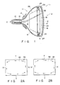
- Fig. 1 shows a conventional shadow mask type color cathode ray tube.
- a color cathode ray tube 1 comprises a panel section 2 including a faceplate 4, having a substantially rectangular shape, and a skirt 6 extending from the edge of the faceplate 4, and an envelope 11 including a funnel section 8 connected to the panel section 2 and a neck section 10 continuous to the funnel section 8.
- a vacuum is created in the cathode ray tube 1 by the panel section 2, funnel section 8 and neck section 10.
- An electron gun assembly 12 for producing three electron beams 13 is housed in the neck section 10.
- a deflecting system 14 is arranged on the outside of the cone section of the funnel section 8. The deflecting system 14 produces a magnetic field to deflect the electron beams 13 in a horizontal direction and in a vertical direction.
- a phosphor screen 16 is formed on the inner surface of faceplate 4 of panel section 2.
- a substantially rectangular shadow mask 18 is arranged so as to face the phosphor screen 16 such that a predetermined gap is produced between the shadow mask 18 and the faceplate 4.
- the shadow mask 18 is formed of a thin metallic plate and has a number of slit holes 20.
- a mask frame 22 surrounds the peripheral surface of the shadow mask 18.
- the mask frame 22 is supported by a plurality of elastic supports 23.
- a plurality of stud pins 24 engaging the elastic supports 23 are mounted on the inner surface of the skirt 6.
- the mask frame 22 is provided with an internal magnetic shield 26 for reducing terrestrial magnetic influence upon the electron beams.
- the three electron beams 13 emitted from the electron gun 12 are deflected by the deflecting system 14.
- the deflected electron beams 13 are converged in the vicinity of the slit holes 20 of shadow mask 18.
- the converged beams 13 are made incident on predetermined areas of phosphor screen 16 where red light, green light and blue light are produced, respectively.
- the electron beams 13 produced by electron guns 12 cause the red, green and blue light to be emitted from the phosphor screen 16.
- the internal magnetic shield serves to reduce the terrestrial magnetic influence upon the electron beams.
- the electron beams emitted from the electron guns are influenced by terrestrial magnetism, and the trajectory thereof are changed. If the trajectory of the electron beams are changed from normal ones, the electron beams do not land on predetermined areas on the phosphor screen. The landing error leads to discoloration on the faceplate and lower picture quality.
- Fig. 3 shows the horizontal lines of magnetic force produced in the tube having the internal magnetic shield (vertical lines of magnetic force are omitted). In this case, the faceplate faces northwards.
- the lines of magnetic force produced between the electron gun assembly and the shadow mask are distributed, as indicated by solid lines 36.
- the lines of magnetic force between the shadow mask and panel section 2 are indicated by solid lines 38.
- the lines of magnetic force are distributed as shown by broken lines 40.
- the lines of magnetic force are changed, as shown by solid lines 36 and 38.
- the internal magnetic shield 26, shadow mask 18 and mask frame 22, which are formed of magnetic material, constitute a magnetic circuit (a region of low magnetic resistance).
- the magnetic flux density in a region within the magnetic circuit is reduced to 1/10. Namely, since the lines 36 of magnetic force are changed through the magnetic members, or the internal magnetic shield 26, shadow mask 18 and mask frame 22, the magnetic flux density in the region where electron beams 13 pass is decreased.
- the lines 36 of magnetic force which have passed through the shadow mask 18, becomes lines of 38 of magnetic force which extend through a vacuum and the face plate 4.
- the lines 38 of magnetic force are biased toward the tube axis.
- the magnetic flux density of lines 38 in the vicinity of the shadow mask 18 becomes higher than that of normal lines 40 of magnetic force.
- Fig. 4 shows mask frame 22 disclosed in Japanese Patent Disclosure No. 43242/88, which is designed to reduce the landing error of electron beams.
- the mask frame has a spring-like metallic support 42 for elastically supporting shadow mask 18.
- Fig. 5 shows lines of magnetic force produced in the color cathode ray tube in which the support 42 is used. The use of the support 42 prevents the lines of magnetic force from being emitted from the shadow mask 18. In this case, the lines of magnetic force are almost emitted from the mask frame 22. Thus, the magnetic influence on the electron beams produced between the shadow mask and the phosphor screen is reduced, and the landing error of the electron beams is reduced.
- the spring-like support 42 is used in a color cathode ray tube used in a recently developed large-sized high-definition television set having an aspect ratio of 16 : 9, above-described landing error of electron beams in a direction shown in Fig. 2A or Fig. 2B occurs.
- a faceplate of this tube is arranged to face northwards
- the landing locations of the beams are shifted in the direction the arrow shown in Fig. 2A.
- the faceplate is arranged to face southwards
- the landing locations of the beams are shifted in the direction of the arrow shown in Fig. 2B. Namely, the landing locations of the beams are changed so as to circulate over the faceplate.
- FIG. 6 shows the sum (N/S beam movement amount) of the amount of the landing error in the case of Fig. 2A (the faceplate facing northwards) and the amount of the landing error in the case of Fig. 2B (the faceplate facing southwards).
- the sum of the landing errors at a corner is 98 ⁇ m
- the sum of the landing errors at an end area on a horizontal axis (X-axis) is 63 ⁇ m
- the sum of the landing errors at an end area on a vertical axis (Y-axis) is 33 ⁇ m.
- the pitch of each aperture of a shadow mask is 0.39 to 0.48 mm.
- the diameter ⁇ d of each phosphor dot 41 on a phosphor screen is about 170 ⁇ m
- the diameter ⁇ b of a spot 43 of each electron beam is about 240 ⁇ m.
- Sine a tolerance of a landing error of each electron beam is about 35 ⁇ m, an allowance of color purity is very small.
- the landing error of the beams leads to degradation of color purity.
- a terrestrial magnetism correction coil 44 shown in Figs. 8A and 8B The coil 44 is supplied with a DC current to produce a magnetic field in a direction opposite to the direction of terrestrial magnetism.
- Fig. 9A shows a landing error of electron beams in the case where an electric current is not caused to flow in the terrestrial magnetism correction coil 44 used in color cathode ray tube of a 36-inch 90°-deflection type high-definition television set.
- the landing error of electron beams at a corner area is 49 ⁇ m
- the landing error at an end area on an X-axis is 32 ⁇ m
- the landing error at an end area on a Y-axis is 17 ⁇ m.
- FIG. 9B shows the landing error of election beams when the coil 44 is supplied with an electric current to correct the landing error.
- the landing error at a corner area is zero, but the landing error at the end area on the X-axis becomes 17 ⁇ m, and the landing error at the end area on the Y-axis becomes 32 ⁇ m.
- the correction by the terrestrial magnetism correction coil becomes excessive at the end areas on the X- and Y-axes. Under the circumstance, the correction by the terrestrial magnetism correction coil is not satisfactory.
- the present invention has been devised under the above circumstance, and the object of this invention is to provide a color cathode ray tube having a high color purity, wherein lines of magnetic force of terrestrial magnetism are prevented from acting on electron beams.
- the cathode ray tube of the present invention comprises: a vacuum envelope comprising a panel section, a funnel section and a neck section, the panel section having an axis and a faceplate, a front view shape of which is substantially rectangular and which has an inner surface and having a skirt extending from a peripheral edge of the faceplate, the funnel section being continuous to the neck section; a phosphor screen formed on the inner surface of the faceplate; a shadow mask arranged in the panel section to oppose the phosphor screen on the faceplate; a mask frame arranged around the shadow mask; a magnetic resistance section provided between the shadow mask and the mask frame; and an electron gun assembly housed in the neck section.
- the landing error of electron beams on the phosphor screen can be reduced, and a color cathode ray tube having a very high picture quality can be provided.
- FIG. 10 shows a color cathode ray tube according to an embodiment of the present invention.
- a color cathode ray tube 80 comprises a panel section 82 including a faceplate 84, having a substantially rectangular shape, and a skirt 86 extending from the edge of the faceplate 84, and an envelope 91 including a funnel section 88 connected to the panel section 82 and neck section 90 continuous to the funnel section 88.
- a vacuum is created in the cathode-ray tube 80 by the panel section 82, funnel section 88 and neck section 90.
- An electron gun assembly 92 for producing three electron beams 93 is housed in the neck section 90.
- a deflecting system 94 is arranged on the outside of the cone section the funnel section 88.
- the deflecting system 94 produces a magnetic field to deflect the electron beams 93 in a horizontal direction and in a vertical direction.
- a phosphor screen 96 is formed on the inner surface of faceplate 84 of panel section 82.
- a substantially rectangular shadow mask 98 is arranged so as to face the phosphor screen 96 such that a predetermined gap is produced between the shadow mask 98 and the faceplate 84.
- the shadow mask 88 is formed of a thin metallic plate and has a number of slit holes 100.
- a mask frame 102 surrounds the peripheral surface of the shadow mask 98.
- the mask frame 102 is supported by a plurality of elastic supports 103.
- a plurality of stud pins 104 engaging the elastic supports 103 are mounted on the inner surface of the skirt 86.
- the mask frame 102 is provided with an internal magnetic shield 106 for reducing magnetic influence upon the electron beams.
- Terrestrial magnetism correction coil 107 is arranged at the outer surface of envelope 91 and near skirt 86.
- the three electron beams 93 emitted from the electron gun 92 are deflected by the deflecting system 94.
- the deflected electron beams 93 are converged in the vicinity of the slit holes 100 of shadow mask 98.
- the converged beams 93 are made incident on predetermined areas of phosphor screen 96 where red light, green light and blue light are produced, respectively.
- the electron beams 93 produced by electron gun 92 cause the red, green and blue light to be emitted from the phosphor screen 96.
- the shadow mask is made of 99% of Fe and 0.03 to 0.04% of Al, and has a magnetic permeability of 9.30 ⁇ 10 ⁇ 4 H/m (relative magnetic permeability is 740).
- the mask frame 102 is made of a material containing low-carbon steel as a main component, and is formed of a plate having a thickness of 0.8 mm and an L-shaped cross section.
- the magnetic permeability of the mask frame 102 is 6.28 ⁇ 10 ⁇ 4 H/m (relative magnetic permeability is 500)
- a gap 110 is provided between the shadow mask 98 and the mask frame 102.
- the width of gap 110 is smallest at a central area of a longer side of mask frame 102, and is second smallest at a central area of a shorter side of mask frame 102.
- the width of the gap increases towards each corner of mask frame 102, and becomes greatest at the corner.
- the width of the gap 110 is equal to or greater than the thickness of the mask frame 102.
- each magnetic resistance member 112 which are each made of a non-magnetic material or a magnetic material having a lower magnetic permeability than that of that of shadow mask 98 or mask frame 102, are arranged at the corresponding four corners of mask frame 102.
- Each magnetic resistance member 112 has a thickness of 1.0 mm and is made of a non-magnetic stainless steel (SUS304L, SUS302) having a magnetic permeability of about 1.257 ⁇ 10 ⁇ 6 H/m (relative magnetic permeability is about 1).
- SUS304L, SUS302 non-magnetic stainless steel having a magnetic permeability of about 1.257 ⁇ 10 ⁇ 6 H/m (relative magnetic permeability is about 1).
- Figs. 12A and 12B show lines of terrestrial magnetic force produced in the faceplate of the color cathode ray tube 80 which is arranged to face northwards.
- Fig. 12A shows a corner area of the tube 80
- Fig. 12B shows a part of a peripheral area of the tube 80 on the X-axis or Y-axis.
- magnetic resistance member 112 for fixing shadow mask 98 to mask frame 102 is arranged between shadow mask 98 and mask frame 102
- gap 110 is provided between the magnetic resistance member 112 and the mask frame 102.
- gap 110 is provided between shadow mask 98 and mask frame 102.
- Lines 114 of magnetic force produced in a region closer to internal magnetic shield 106 than to shadow mask 98 are collected by magnetic shield 106.
- the lines 114 of magnetic force pass through internal magnetic shield 106 and mask frame 102, and then the lines 114 are radiated as lines 116 of magnetic force.
- the lines 116 of magnetic force do not flare in a wide range, and pass through a region near the periphery of phosphor screen 96.
- magnetic resistance member 112 is provided, and also gap 110 is provided.
- lines 116 of magnetic force are rarely radiated through shadow mask 98, and electron beam 93 which has passed through shadow mask 98 is not deflected by the lines of 116 of magnetic force and is landed on phosphor screen 96. Since the width of gap 110 between shadow mask 98 and mask frame 102 is smaller in the corner area than in the areas on the X- and Y-axes, the lines 116 of magnetic force are biased toward the tube axis.
- Fig. 13A shows landing errors of electron beams in this embodiment, in the case where an electric current is not caused to flow through the terrestrial magnetism correction coil. Namely, the landing error in the area on the X-axis is 35 ⁇ m, that in the area on the Y-axis is 30 ⁇ m, and that in the corner section is 38 ⁇ m. Compared to the difference between the maximum landing error and the minimum landing error in the prior art shown in Fig.
- Fig. 13B shows landing errors of electron beams in this embodiment, in the case where an electric current is caused to flow through the terrestrial magnetism correction coil. Namely, the landing error in the area on the X-axis is 5 ⁇ m, that in the area on the Y-axis is 8 ⁇ m, and that in the corner section is zero. Since the difference between the maximum landing error and the minimum landing error is small, the lading errors can be easily corrected by the terrestrial magnetism correction coil.
- the faceplate of the tube is arranged to face southwards.
- the directions of the lines of magnetic force are reversed. Even if the directions of the lines of magnetic force are reversed, the amount of landing errors is unchanged.
- the same correction of the landing errors can be performed by reversing the direction of the electric current supplied to the terrestrial magnetism correction coil.
- the landing errors of beams can be suitably corrected by causing a suitable electric current to flow through the terrestrial magnetism correction coil in accordance with the intensity of the terrestrial magnetism.
- the landing errors of electron beams are substantially uniform over the entire surface of the shadow mask. Since the landing errors can be efficiently corrected by the terrestrial magnetism correction coil, a color cathode ray tube having a high color purity can be manufactured.
- Fig. 14 shows a first modification of the above embodiment of the present invention.
- a number of holes 121 are formed in shadow mask 120.
- the shadow mask 120 is fixed to a mask frame 122 having curved four sides.
- Magnetic resistance members 124 are provided at corner areas between shadow mask 120 and mask frame 122, and other magnetic resistance members 126 are provided at central areas of the sides of mask frame 122.
- a gap 127 is produced between shadow mask 120 and mask frame 124.
- the width of gap 127 is smallest at a central area of a longer side of mask frame 122 and second smallest at a central area of a shorter side of mask frame 122.
- the width of the gap gradually increases from the central area of each side towards each corner area.
- the width of gap 127 becomes largest at each corner area.
- the width of the gap is equal to or larger than the thickness of the mask frame 122.
- the shadow mask of a conventional shape can be used by forming shadow mask 122 having the above shape.
- the magnetic resistance members 126 provided at central areas of the four sides of mask frame 122 increase the mechanical strength of shadow mask 120.
- each side of mask frame 122 is curved, the degree of freedom of design of mask supports (not shown) attached to mask frame 122 is increased.
- the same advantages as are obtainable with the above-described embodiment can be obtained with the first modification. It is possible to arrange only magnetic resistance members between shadow mask 120 and mask frame 122 at the corners, without using magnetic resistance members 126. Inversely, it is possible to arrange only magnetic resistance members at the mid-portions of the each sides, without using magnetic resistance members 124.
- FIG. 15 shows a second modification of the above-described embodiment of the present invention.
- a number of holes 131 are formed in shadow mask 130.
- a magnetic resistance member 132 formed of a non-magnetic stainless steel band or an aluminum band is provided around shadow mask 130.
- the shadow mask 130 is attached on mask frame 134 having four curved sides.
- Magnetic resistance members 136 are provided at areas between the magnetic resistance member 132 and mask frame 134.
- a gap 138 is produced between shadow mask 130 and mask frame 134. The width of gap 138 is smallest at a central area of a longer side of mask frame 134, and second smallest at a central area of a shorter side of mask frame 134.
- the width of gap 138 gradually increases from the central areas of the four sides of mask frame 134 towards corner areas of mask frame 134.
- the width of gap 138 is largest at the corner areas.
- the shadow mask may be made of iron or invar containing 62.9% of Fe and 36.4% of Ni and having a magnetic permeability of 4.02 ⁇ 10 ⁇ 3 H/m (relative magnetic permeability is 3200).
- the thickness of the shadow mask, if made of invar, is 0.8 mm. It is desirable that the magnetic resistance member be made of a material having a lowest possible magnetic permeability, for example, Cr, Al, Cu, or glass.
- the color cathode ray tube is provided with an internal magnetic shield.
- the tube may not be provided with such a magnetic shield.
- a color cathode ray tube having similar advantages can also be manufactured.
Landscapes
- Electrodes For Cathode-Ray Tubes (AREA)
- Video Image Reproduction Devices For Color Tv Systems (AREA)
Applications Claiming Priority (4)
| Application Number | Priority Date | Filing Date | Title |
|---|---|---|---|
| JP200614/88 | 1988-08-11 | ||
| JP20061488 | 1988-08-11 | ||
| JP1172497A JP2922533B2 (ja) | 1988-08-11 | 1989-07-04 | カラー受像管 |
| JP172497/89 | 1989-07-04 |
Publications (3)
| Publication Number | Publication Date |
|---|---|
| EP0354577A2 true EP0354577A2 (de) | 1990-02-14 |
| EP0354577A3 EP0354577A3 (de) | 1991-03-27 |
| EP0354577B1 EP0354577B1 (de) | 1996-10-23 |
Family
ID=26494840
Family Applications (1)
| Application Number | Title | Priority Date | Filing Date |
|---|---|---|---|
| EP89114843A Expired - Lifetime EP0354577B1 (de) | 1988-08-11 | 1989-08-10 | Farbbildröhre |
Country Status (4)
| Country | Link |
|---|---|
| US (1) | US5029256A (de) |
| EP (1) | EP0354577B1 (de) |
| CN (1) | CN1014375B (de) |
| DE (1) | DE68927360T2 (de) |
Cited By (2)
| Publication number | Priority date | Publication date | Assignee | Title |
|---|---|---|---|---|
| FR2756662A1 (fr) * | 1996-11-30 | 1998-06-05 | Lg Electronics Inc | Tube a rayons cathodiques plat muni d'un rail de support de masque perfore et d'ecran magnetique |
| US6812630B2 (en) | 2000-02-07 | 2004-11-02 | Matsushita Electric Industrial Co., Ltd. | Cathode-ray tube |
Families Citing this family (7)
| Publication number | Priority date | Publication date | Assignee | Title |
|---|---|---|---|---|
| DE69405677T2 (de) * | 1993-10-22 | 1998-03-19 | Philips Electronics Nv | Farbbildröhre mit einer magnetischen Abschirmung |
| US6034744A (en) * | 1994-08-11 | 2000-03-07 | Lg Electronics Inc. | Magnetism shield for cathode ray tube |
| KR200147273Y1 (ko) * | 1995-09-25 | 1999-06-15 | 손욱 | 칼라 음극선관용 마스크 프레임과 인너 시일드의 어셈블리 |
| US6188170B1 (en) * | 1996-07-12 | 2001-02-13 | Kabushiki Kaisha Toshiba | Color cathode ray tube including mask frame with protruding portions |
| JP2001185043A (ja) * | 1999-12-28 | 2001-07-06 | Matsushita Electric Ind Co Ltd | 陰極線管 |
| US7199512B2 (en) * | 2003-09-17 | 2007-04-03 | Lg. Philips Displays Korea Co., Ltd. | Color cathode ray tube |
| DK2202761T3 (da) * | 2008-11-24 | 2011-07-25 | Nexans | Anordning med et supraledende kabel |
Family Cites Families (7)
| Publication number | Priority date | Publication date | Assignee | Title |
|---|---|---|---|---|
| JPS59207542A (ja) * | 1983-05-10 | 1984-11-24 | Toshiba Corp | 陰極線管 |
| FR2555808B1 (fr) * | 1983-11-25 | 1986-10-10 | Videocolor | Masque d'ombre pour tube d'image en couleurs et tube d'image le comportant |
| JPH07118272B2 (ja) * | 1985-03-27 | 1995-12-18 | 株式会社東芝 | カラ−受像管 |
| DE3603476A1 (de) * | 1986-02-05 | 1987-08-06 | Licentia Gmbh | Bildschirmgeraet |
| US4694216A (en) * | 1986-05-27 | 1987-09-15 | Rca Corporation | Cathode-ray tube having an internal magnetic shield |
| JPH07118276B2 (ja) * | 1986-05-28 | 1995-12-18 | 株式会社東芝 | カラー受像管 |
| JPS6343242A (ja) * | 1986-08-06 | 1988-02-24 | Nec Corp | カラ−受像管 |
-
1989
- 1989-08-10 EP EP89114843A patent/EP0354577B1/de not_active Expired - Lifetime
- 1989-08-10 CN CN89105559A patent/CN1014375B/zh not_active Expired
- 1989-08-10 US US07/391,925 patent/US5029256A/en not_active Expired - Lifetime
- 1989-08-10 DE DE68927360T patent/DE68927360T2/de not_active Expired - Fee Related
Cited By (2)
| Publication number | Priority date | Publication date | Assignee | Title |
|---|---|---|---|---|
| FR2756662A1 (fr) * | 1996-11-30 | 1998-06-05 | Lg Electronics Inc | Tube a rayons cathodiques plat muni d'un rail de support de masque perfore et d'ecran magnetique |
| US6812630B2 (en) | 2000-02-07 | 2004-11-02 | Matsushita Electric Industrial Co., Ltd. | Cathode-ray tube |
Also Published As
| Publication number | Publication date |
|---|---|
| EP0354577A3 (de) | 1991-03-27 |
| DE68927360T2 (de) | 1997-03-20 |
| US5029256A (en) | 1991-07-02 |
| DE68927360D1 (de) | 1996-11-28 |
| EP0354577B1 (de) | 1996-10-23 |
| CN1014375B (zh) | 1991-10-16 |
| CN1040459A (zh) | 1990-03-14 |
Similar Documents
| Publication | Publication Date | Title |
|---|---|---|
| US4229675A (en) | Color picture tube with internal funnel shaped magnetic shield | |
| US5029256A (en) | Color cathode ray tube | |
| EP0247793B1 (de) | Kathodenstrahlröhre mit innerer magnetischer Abschirmung | |
| US5059858A (en) | Color cathode ray tube apparatus | |
| JP2892046B2 (ja) | カラー受像管 | |
| US6124668A (en) | Color cathode ray tube | |
| HK1004301B (en) | Cathode-ray tube having an internal magnetic shield | |
| US5990607A (en) | Shadow mask for color CRT and method for forming same | |
| US4857796A (en) | Cathode-ray tube with electrostatic convergence means and magnetic misconvergence correcting mechanism | |
| EP0325207A2 (de) | Farbbildröhre | |
| US4659961A (en) | Cup member of an in-line electron gun capable of reducing a coma aberration | |
| KR890004872B1 (ko) | 칼라 수상관 장치 | |
| EP0311806A1 (de) | Ablenkeinheit für Farbkathodenstrahlvorrichtung | |
| US6388368B2 (en) | Color cathode ray tube having an improved internal magnetic shield | |
| US5880555A (en) | Color cathode ray tube and a magnetic shielding body therefor | |
| US5521463A (en) | Cathode ray tube having a cancel coil for earth magnetism | |
| JP2922533B2 (ja) | カラー受像管 | |
| US4983995A (en) | Exposure device for forming phosphor deposited screen in in-line cathode ray tube | |
| US6700320B2 (en) | Cathode ray tube with structure for preventing electron beam mis-landing caused by geomagnetism | |
| US5763994A (en) | Cathode ray tube having a corrector for a deflection yoke | |
| US6509936B1 (en) | Cathode ray tube with magnetic coil for display enhancement | |
| KR100213785B1 (ko) | 칼라음극선관의 자기쉴드 | |
| JP2614208B2 (ja) | カラー受像管 | |
| EP0173940A1 (de) | Farbbildgerät | |
| KR100596233B1 (ko) | 컬러 음극선관 |
Legal Events
| Date | Code | Title | Description |
|---|---|---|---|
| PUAI | Public reference made under article 153(3) epc to a published international application that has entered the european phase |
Free format text: ORIGINAL CODE: 0009012 |
|
| 17P | Request for examination filed |
Effective date: 19890907 |
|
| AK | Designated contracting states |
Kind code of ref document: A2 Designated state(s): DE FR GB |
|
| PUAL | Search report despatched |
Free format text: ORIGINAL CODE: 0009013 |
|
| AK | Designated contracting states |
Kind code of ref document: A3 Designated state(s): DE FR GB |
|
| 17Q | First examination report despatched |
Effective date: 19930712 |
|
| GRAH | Despatch of communication of intention to grant a patent |
Free format text: ORIGINAL CODE: EPIDOS IGRA |
|
| GRAH | Despatch of communication of intention to grant a patent |
Free format text: ORIGINAL CODE: EPIDOS IGRA |
|
| GRAA | (expected) grant |
Free format text: ORIGINAL CODE: 0009210 |
|
| AK | Designated contracting states |
Kind code of ref document: B1 Designated state(s): DE FR GB |
|
| REF | Corresponds to: |
Ref document number: 68927360 Country of ref document: DE Date of ref document: 19961128 |
|
| ET | Fr: translation filed | ||
| PLBE | No opposition filed within time limit |
Free format text: ORIGINAL CODE: 0009261 |
|
| STAA | Information on the status of an ep patent application or granted ep patent |
Free format text: STATUS: NO OPPOSITION FILED WITHIN TIME LIMIT |
|
| 26N | No opposition filed | ||
| REG | Reference to a national code |
Ref country code: GB Ref legal event code: 746 Effective date: 19981026 |
|
| REG | Reference to a national code |
Ref country code: FR Ref legal event code: D6 |
|
| REG | Reference to a national code |
Ref country code: GB Ref legal event code: IF02 |
|
| PGFP | Annual fee paid to national office [announced via postgrant information from national office to epo] |
Ref country code: DE Payment date: 20070802 Year of fee payment: 19 |
|
| PGFP | Annual fee paid to national office [announced via postgrant information from national office to epo] |
Ref country code: GB Payment date: 20070809 Year of fee payment: 19 |
|
| PGFP | Annual fee paid to national office [announced via postgrant information from national office to epo] |
Ref country code: FR Payment date: 20080818 Year of fee payment: 20 |
|
| GBPC | Gb: european patent ceased through non-payment of renewal fee |
Effective date: 20080810 |
|
| PG25 | Lapsed in a contracting state [announced via postgrant information from national office to epo] |
Ref country code: DE Free format text: LAPSE BECAUSE OF NON-PAYMENT OF DUE FEES Effective date: 20090303 |
|
| PG25 | Lapsed in a contracting state [announced via postgrant information from national office to epo] |
Ref country code: GB Free format text: LAPSE BECAUSE OF NON-PAYMENT OF DUE FEES Effective date: 20080810 |