EP0354732A2 - Systèmes de capteurs optiques - Google Patents
Systèmes de capteurs optiques Download PDFInfo
- Publication number
- EP0354732A2 EP0354732A2 EP89307934A EP89307934A EP0354732A2 EP 0354732 A2 EP0354732 A2 EP 0354732A2 EP 89307934 A EP89307934 A EP 89307934A EP 89307934 A EP89307934 A EP 89307934A EP 0354732 A2 EP0354732 A2 EP 0354732A2
- Authority
- EP
- European Patent Office
- Prior art keywords
- optical
- interferometer
- source
- signal
- transducer
- Prior art date
- Legal status (The legal status is an assumption and is not a legal conclusion. Google has not performed a legal analysis and makes no representation as to the accuracy of the status listed.)
- Granted
Links
Images


Classifications
-
- G—PHYSICS
- G01—MEASURING; TESTING
- G01D—MEASURING NOT SPECIALLY ADAPTED FOR A SPECIFIC VARIABLE; ARRANGEMENTS FOR MEASURING TWO OR MORE VARIABLES NOT COVERED IN A SINGLE OTHER SUBCLASS; TARIFF METERING APPARATUS; MEASURING OR TESTING NOT OTHERWISE PROVIDED FOR
- G01D5/00—Mechanical means for transferring the output of a sensing member; Means for converting the output of a sensing member to another variable where the form or nature of the sensing member does not constrain the means for converting; Transducers not specially adapted for a specific variable
- G01D5/26—Mechanical means for transferring the output of a sensing member; Means for converting the output of a sensing member to another variable where the form or nature of the sensing member does not constrain the means for converting; Transducers not specially adapted for a specific variable characterised by optical transfer means, i.e. using infrared, visible, or ultraviolet light
- G01D5/268—Mechanical means for transferring the output of a sensing member; Means for converting the output of a sensing member to another variable where the form or nature of the sensing member does not constrain the means for converting; Transducers not specially adapted for a specific variable characterised by optical transfer means, i.e. using infrared, visible, or ultraviolet light using optical fibres
Definitions
- the present invention relates to optical transducer systems, and is more particularly concerned with optical transducer systems of the kind involving an optical transducer which produces a wavelength multiplexed output signal, such as the transducer described in our United Kingdom Patent Application No. 8730156 (Publication No. 2 209 101A).
- a wavelength multiplexed optical position transducer is described in our aforementioned United Kingdom patent application.
- This transducer uses a graded-index rod lens and a glass wedge grating assembly to disperse and recombine a broad spectrum optical signal generated by an LED.
- the dispersed light is reflected by a coded strip and the combination of wavelengths present in the recombined spectrum is a function of the position of the lens/grating assembly relative to the coded strip.
- the recombined signal from a transducer is transmitted along a single optical fibre to a detector system.
- the detector system wavelength demultiplexes the received signal in a further wedge/grating assembly.
- a ten bit coded strip is used in the transducer to reflect the various wavelengths in the dispersed optical signal.
- a further channel is used to provide a continuous ON signal for use as a reference signal channel.
- This reference channel is used to compensate for wavelength-independent variable system losses such as poor optical connections, bent fibres, and ageing of the LED's.
- wavelength-dependent, variations in intensity caused by factors such as temperature variations of the LEDs.
- the LEDs could have their temperatures stabilised by using PELTIER coolers but this is not a practical solution in many applications due to the low lifetime of Peltier coolers at elevated temperatures (eg 10,000 hours at 125°C).
- an optical transducer system comprising a broadband optical signal source, an interferometer coupled to receive a broadband optical signal from the source, means for varying the wavelength of the optical signal transmitted by the interferometer, an optical transducer coupled to receive the varying wavelength optical signal transmitted by the interferometer and responsive thereto to produce a wavelength multiplexed optical output signal representative of a parameter being monitored by the transducer, and detector means coupled to receive and monitor the optical output signal from the transducer.
- the detector means is coupled to receive and compare the optical output signal from the transducer and the varying wavelength optical signal from the interferometer.
- the varying wavelength optical signal from the interferometer is used to provide a threshold level with which the output signal from the transducer is compared, whereby to compensate automatically for any wavelength drift in the source and any changes in the overall transmission characteristics in the interferometer.
- a variable wavelength optical source for a wavelength multiplexed optical transducer, the source comprising a broadband optical source, an interferometer coupled to receive a broadband optical signal from the source, and means for periodically varying the wavelength passed by the interferometer so as to produce a swept wavelength optical output signal for application to the transducer.
- the interferometer is preferably a Fabry-Perot interferometer
- the broadband source preferably comprises at least two light emitting diodes with different but partially overlapping output spectra.
- control means for maintaining the amplitude of the optical signal transmitted by the interferometer substantially constant, which control means preferably comprises a photo-sensitive detector coupled to receive the optical signal transmitted by the interferometer, a differential amplifier coupled to receive the output of the photo-sensitive detector and a reference level so as to produce a control signal dependent upon the difference therebetween, a variable current source for supplying drive current to the light-emitting diodes, and a control circuit coupled to the variable current source and responsive to the control signal to vary the drive current to the light emitting diodes so as to tend to reduce said difference.
- apparatus to decode a wavelength multiplexed optical signal comprising an interferometer receiving the wavelength multiplexed optical signal and also receiving a source optical signal from which the wavelength multiplexed optical signal is generated, both the optical signals being filtered by the interferometer in parallel, means for varying the wavelength passed by the interferometer, and means for monitoring the two optical signals transmitted by the interferometer.
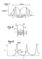
- the spectrum shown in Figure 1 is the type that would be received from an optical position transducer which uses a coded reflective strip to reflect different wavelengths of a dispersed spectrum according to the position of the coded strip.
- the bandwidth of the spectrum illustrated is 100nm.
- Each channel is received as a '1' or a '0'.
- the non-zero levels 2 of the '0' state are present after transmission through an optical fibre and are caused by back reflections in the fibre.
- the envelope of the spectrum is indicated by the dotted line.
- the ratio of the on/off states is typically in the range of 4-6dB.
- a Fabry-Perot interferometer may be used to decode such a spectrum and a schematic cross-section through an FP is shown in Figure 2. This shows the passage of light through the FP for a given separation d of the two parallel, partially transmitting mirrors 4 and 6 which have reflectivities R1 and R2 respectively.
- Figure 3 shows the spectral transmission characteristics of an FP. This consists of a series of peaks (or orders) of width ⁇ , separated by the free spectral range (fsr), ⁇ .
- the ratio ⁇ / ⁇ is called the finesse and for a high-quality FP this is in the range 40-100.
- the peak transmission would be 100%, but in practice this will be in the range 50-70%.
- the wavelength position of the transmitted peaks is dependent upon the spacing d of the mirrors of the FP. Changing d by ⁇ /2 will move the order n peak to the position of the order n+1 (or n-1) peak. Therefore, if the fsr is in the range 150-200nm, the transmission peak of order n can be scanned across the full LED spectrum of Figure 1. If the fsr is 200 nm and the finesse is 50 then the peak width will be 4 nm. This then enables the peak to be scanned through and to resolve the spectrum of Figure 1 by varying the gap between the mirrors.
- An optical transducer system which uses an FP in the detector is shown in Figure 4.
- Two source LEDs 8 direct broad band light down two optical fibres 10.
- the fibres are connected to a fibre optic coupler 12 which transmits light from the two LEDs down a single optical fibre 14 connected to one of its outputs.
- This fibre 14 is connected to the input of an optical position transducer 16. No details of this transducer are given: it may be as described in the aforementioned application.
- the output of the transducer 16 is connected to a further optical fibre 18, which is in turn connected to the input of an FP 20.
- the output of the FP 20 illuminates a photo-sensitive detector 21 which provides an output signal proportional to intensity. Changing the gap width of the FP enables the whole spectrum output by the transducer 16 to be scanned through to detect the peaks representing each '1', so that the position can be determined from the output of the photo-sensitive detector.
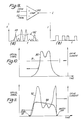
- Piezo-electric crystals may be used to alter the positions of the mirrors in an FP (such as in the WD1 FP wavelength demultiplexer produced by Queensgate Instruments Ltd), and the shape of the voltage waveform applied to them will correspond to the variation in d with time, as shown in Figure 5.
- This is a simple triangular waveform.
- the resultant output of the FP as picked up by the photo-sensitive detector 21 is shown beneath the triangular waveform.
- the intensities representing data values of '1' or '0' are detected by the photo-sensitive 21.
- a six bit code is shown in Figure 5, and it can be seen that the output on the negative-going slope of the triangular waveform is the mirror image of that on the positive-going slope.
- Large humps 3 may be produced between the groups of data channels due to imperfect mirror coatings, but these do not have any serious effect on the data output.
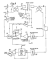
- the optical transducer system of the present invention as shown in Figure 6, is provided.
- This system comprises the two source LEDs 8 connected via the optical fibres 10 to the coupler 12, but the output of the coupler 12 transmits light from the two LEDs to the input of an FP 50 (instead of to the input of the transducer 16).
- the FP 50 is driven by (ie has the gap d between its mirrors varied by) the triangular waveform of Figure 5, and its output is connected to an input port of a second coupler 52.
- the coupler 52 has two output ports 54, 56 between which light at the input of the coupler is preferably divided in the ratio 100:1 (although the use of lower ratios is feasible).
- the portion of the light leaving the coupler 52 via its output port 54 is directed via the optical fibre 14 to the transducer 16, whose output is connected via the optical fibre 18 to a first photo-sensitive detector 58, while the portion of the light leaving the other output port 56 of the coupler 52 is directed via a variable attenuator 60 to a second photo-sensitive detector 62.
- the combination of the LEDs 8 and the FP 50 operates as a tunable broadband source, so that the light arriving at the transducer 16 has its wavelength periodically swept first in one direction and then in the other.
- the output of the transducer 16 is therefore time multiplexed as well as wavelength multiplexed.
- the photo-sensitive detectors 28 simultaneously monitor the time-varying output spectrum from the transducer 16 and the simultaneously time-varying spectrum from the FP 50 (ie the input spectrum to the transducer 16). These two spectra are illustrated in Figure 7, the transducer spectrum (a) being formed from large and small peaks representing '1' or '0' values respectively, and the source spectrum (b) being a continuous broadband signal. Since both spectra take the same optical path through the FP 50, they both see the same optical characteristics in terms of mirror spacing, mirror reflectivities etc. This is in practice very important since the mirrors may not be perfectly flat and parallel.
- the spectrum received by detector 62 is used as a threshold level for the transducer signal, as shown in Figure 8.
- the outputs from the two detectors 58, 62 are connected to the inputs of a comparator 66.
- the level of the transducer spectrum exceeds the level of the source spectrum, which is set to a suitable amplitude by the attenuator 60 as shown in the graph of Figure 8(a)
- the output C of the comparator 66 goes high as shown in the graph of Figure 8(b).
- the system of Figure 9 still comprises the two source LEDs 8 connected via the optical fibres 10, the coupler 12, the FP 50 and the coupler 52 to the transducer 16 on the one hand and to the photo-sensitive detector 62 on the other hand, but the output of the photo-sensitive detector 62 is connected to one input of a differential amplifier 70 whose other input is connected to receive a reference voltage V R .
- the output of the differential amplifier 70 is connected to the input of an integrator 72, whose output is connected via a switch 74 to the control input of a variable current source 76 which provides the drive current to the two source LEDs 8.
- the integrator 72 is provided with a reset switch 78, the switches 74 and 78 being controlled by a comparator 80 connected to receive a sawtooth voltage waveform, which is also applied to the FP 50 in place of the triangular waveform mentioned earlier: this sawtooth waveform is produced by a suitable sawtooth waveform generator 82, and is illustrated at 84 in Figure 9.
- the comparator 80 momentarily closes the reset switch 78, and then closes the switch 74, just after the beginning of an up-going ramp of the sawtooth voltage waveform produced by the generator 82.
- the output of the integrator 72 immediately begins to ramp up, causing a rapid rise in the current supplied by the current source 76 to the LEDs 8.
- the output of the photo-sensitive detector 62 increases sufficiently for the output of the differential amplifier 70 to change polarity. This causes the output of the integrator 72 to ramp back down, so reducing the drive current to the LEDs 8.
- the drive current to the LEDs 8 tends to follow a curve which is the inverse of the spectrum they would produce with constant drive current, with the result that the amplitude (or intensity) of the optical signal at the output of the FP 50 tends to be uniform over the useful part of its frequency range.
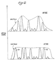
- Figure 10 shows at 90 the variation with time of the amplitude of the optical output signal from the FP 50 at constant drive current (shown at 91) to the source LEDs 8, over half a cycle of operation of the FP 50
- Figure 11 shows at 92 the varying drive current to the LEDs 8 produced by the circuit of Figure 9, and at 93 the resulting variation with time of the amplitude of the optical output signal from the FP 50, again over half a cycle of operation of the FP 50.
- Figure 12 illustrates the improvement between the amplitudes of the bits of the various channels for the FP 50 output signal of Figure 10, shown in the upper half of Figure 12, and the amplitudes of Figure 11, shown in the lower half of Figure 12: the improved signal-to-noise ratio of the channels 95, 96 at the two extremes of the spectrum is readily apparent in the lower half of Figure 12.
- the comparator 80 opens the switch 74, momentarily closes the reset switch 78 to reset the integrator 72, and then closes the switch 74 again just after the sawtooth voltage waveform starts its next up-going ramp, and a sequence of events identical to those of the preceding paragraph is repeated.
- the output of the photo-sensitive detector 58 can be connected to the comparator 66, as in the embodiment of Figures 6 and 8, or to a comparator having its other input connected to receive a reference voltage which is a predetermined proportion, eg 50%, of the reference voltage V R : alternatively and preferably, it is connected to the input of a peak detecting sample-and-hold circuit, shown at 86 in Figure 9.
- the circuit 86 has a reset input which is connected to receive a reset signal from the comparator 80 simultaneously with the operation of the reset switch 78, and its output is connected via a divide-by-two voltage divider 87 to one input of a comparator 88.
- the other input of the comparator 88 is connected to the output of the photosensitive detector 62.
- the peak amplitude of the signal produced by the photodetector 58 for the first channel which is chosen to be the continuously ON reference channel mentioned earlier, is stored in the circuit 86 near the beginning of each cycle of the sawtooth waveform produced by the generator 82, and half this amplitude, produced by the voltage divider 87, is used by the comparator 88 as the reference threshold for detecting the bit values of the remaining ten data channels.
- FIG. 13 Another embodiment of the invention is shown in Figure 13.
- This embodiment again comprises the two source LED's 8, connected via the optical fibres 10 to coupler 12: however, the coupler 12 transmits a first portion of the light to an output connected directly to optical fibre 14, which is again connected to the input of the transducer 16.
- a second portion of the light is transmitted to a second output of the coupler 12, which second output is connected to an optical fibre 122 which transmits light via an attenuator 124 to a port on a first side of a further coupler 126.
- the other port on the first side of the coupler 126 is connected to a photo-sensitive detector 128.
- One port on the opposing side of the coupler 126 is connected to a first side of an FP 130.
- the output of the transducer 16 is again connected to the optical fibre 18, which this time transmits light to a port on a first side of a coupler 132.
- the other port on the first side of coupler 132 is connected to a second photo-sensitive detector 134.
- One port on the opposing side of the coupler 132 is connected to the second side of the FP 130.
- Coupler 132 preferably has a coupling ratio of the order of 3:1.
- the reason for the difference in coupling ratios is to reduce the back reflection from the connection to the FP 30.
- This connection is made with an expanded beam connector.
- This back reflection which reaches detector 128 has to be minimised without significantly reducing the strength of the signal transmitted by the transducer 16 to detector 128.
- light passing from left to right through coupler 126 is attenuated by, for example, -14dB, whilst light passing from right to left if attenuated by -2dB.
- the difference in attenuation levels in the coupler 132 is much less than this and if a 1:1 coupling ratio is used the attenuation will be the same in both directions.
- the back reflection from the source signal reaching detector 128 will have been attenuated much more than the signals from the transducer 16 reaching the detector 128.
- the output signal from the transducer 16 passes through the optical fibre 18, the coupler 132, the FP 130, the coupler 126 and is detected by photo-sensitive detector 128.
- a triangular waveform as shown in Figure 5 is again used to alter the gap d between the mirrors of the FP 130.
- the source light is transmitted via attenuator 124, coupler 126, FP 130, and coupler 132 to photo-sensitive detector 134.
- the photo-sensitive detectors 128 and 134 simultaneously monitor the spectrum from the transducer and the source spectrum.
- the two spectra are again as illustrated in Figure 7, the transducer spectrum (a) being formed from large and small peaks representing '1' or '0' values respectively, and the source spectrum (b) being a continuous broad band signal. Since both spectra again take the same optical path through the FP, they both again see the same optical characteristics in terms of mirror spacing, mirror reflectivities etc. As already mentioned, this is in practive very important since the mirrors may not be perfectly flat and parallel.
- the source spectrum received by detector 134 can be used as a threshold level for the transducer signal, as described hereinbefore with reference to Figure 8. As already explained, using this type of detection, any wavelength drift of the source LED's is automatically compensated for since source and transducer spectra will both drift by the same amount and in the same direction.
- FIG 14. This again comprises the two source LED's 8 connected to one side of the coupler 12.
- the coupler 12 transmits a first portion of the source light to transducer 16 and a second portion of the source light to a dual-ported FP filter 138.
- the output of the transducer 16 is connected to the same side of the FP 138.
- the two photo-sensitive detectors 128, 134 receive the spectra from the transducer and the source respectively.
- the signals from these two photo-sensitive detectors can be used in a similar manner to those of Figure 13, ie the source spectra can be used as a threshold for the transducer spectra.
- FP interferometers may also scan through a range of wavelengths by altering the angle of the mirrors with respect to the direction of travel of the light.
- Such a filter has been described in a paper in Electronics Letters Vol. 24, No. 3, February 1988 entitled “Inline tunable Etalon filter for optical channel selection in high density wavelength division multiplexed fibre systems" by A Frenkel and C Lin.
Landscapes
- Physics & Mathematics (AREA)
- General Physics & Mathematics (AREA)
- Optical Communication System (AREA)
- Spectrometry And Color Measurement (AREA)
- Instruments For Measurement Of Length By Optical Means (AREA)
- Led Devices (AREA)
Applications Claiming Priority (6)
| Application Number | Priority Date | Filing Date | Title |
|---|---|---|---|
| GB8818767 | 1988-08-08 | ||
| GB888818767A GB8818767D0 (en) | 1988-08-08 | 1988-08-08 | Demultiplexers for wavelenght multiplexed signals |
| GB8826746 | 1988-11-16 | ||
| GB888826746A GB8826746D0 (en) | 1988-11-16 | 1988-11-16 | Optical transducer systems |
| GB898914269A GB8914269D0 (en) | 1989-06-21 | 1989-06-21 | Optical transducer systems |
| GB8914269 | 1989-06-21 |
Publications (3)
| Publication Number | Publication Date |
|---|---|
| EP0354732A2 true EP0354732A2 (fr) | 1990-02-14 |
| EP0354732A3 EP0354732A3 (en) | 1990-09-05 |
| EP0354732B1 EP0354732B1 (fr) | 1992-10-28 |
Family
ID=27264015
Family Applications (1)
| Application Number | Title | Priority Date | Filing Date |
|---|---|---|---|
| EP89307934A Expired - Lifetime EP0354732B1 (fr) | 1988-08-08 | 1989-08-03 | Systèmes de capteurs optiques |
Country Status (5)
| Country | Link |
|---|---|
| US (1) | US4972077A (fr) |
| EP (1) | EP0354732B1 (fr) |
| JP (1) | JPH0288905A (fr) |
| DE (1) | DE68903311T2 (fr) |
| GB (1) | GB2225422B (fr) |
Families Citing this family (15)
| Publication number | Priority date | Publication date | Assignee | Title |
|---|---|---|---|---|
| GB9022969D0 (en) * | 1990-10-23 | 1990-12-05 | Rosemount Ltd | Displacement measurement apparatus |
| IT1246572B (it) * | 1991-02-27 | 1994-11-24 | Cise Spa | Procedimento e apparecchio per misure interferometriche assolute di grandezze fisiche. |
| GB2258725B (en) * | 1991-07-30 | 1995-06-21 | Rosemount Ltd | A method of decoding a spectrally modulated light signal |
| GB2312346B (en) * | 1996-04-20 | 2000-07-12 | Northern Telecom Ltd | Marshalling in optical tdma systems |
| US7305158B2 (en) | 2004-04-15 | 2007-12-04 | Davidson Instruments Inc. | Interferometric signal conditioner for measurement of absolute static displacements and dynamic displacements of a Fabry-Perot interferometer |
| US7492463B2 (en) | 2004-04-15 | 2009-02-17 | Davidson Instruments Inc. | Method and apparatus for continuous readout of Fabry-Perot fiber optic sensor |
| US7864329B2 (en) | 2004-12-21 | 2011-01-04 | Halliburton Energy Services, Inc. | Fiber optic sensor system having circulators, Bragg gratings and couplers |
| US7835598B2 (en) | 2004-12-21 | 2010-11-16 | Halliburton Energy Services, Inc. | Multi-channel array processor |
| EP1869737B1 (fr) | 2005-03-16 | 2021-05-12 | Davidson Instruments, Inc. | Capteur fabry-perot haute intensite |
| WO2007033069A2 (fr) | 2005-09-13 | 2007-03-22 | Davidson Instruments Inc. | Algorithme de poursuite pour processeur de signal a reseau lineaire a schemas de correlation croisee de fabry-perot et son procede d'utilisation |
| US7684051B2 (en) | 2006-04-18 | 2010-03-23 | Halliburton Energy Services, Inc. | Fiber optic seismic sensor based on MEMS cantilever |
| US7743661B2 (en) | 2006-04-26 | 2010-06-29 | Halliburton Energy Services, Inc. | Fiber optic MEMS seismic sensor with mass supported by hinged beams |
| US8115937B2 (en) | 2006-08-16 | 2012-02-14 | Davidson Instruments | Methods and apparatus for measuring multiple Fabry-Perot gaps |
| US7787128B2 (en) | 2007-01-24 | 2010-08-31 | Halliburton Energy Services, Inc. | Transducer for measuring environmental parameters |
| CN106725560B (zh) * | 2015-11-19 | 2021-01-12 | 上海联影医疗科技股份有限公司 | 光传感器的性能检测方法和医学成像设备 |
Family Cites Families (18)
| Publication number | Priority date | Publication date | Assignee | Title |
|---|---|---|---|---|
| DE3044183A1 (de) * | 1980-11-24 | 1982-06-24 | Reinhard Dipl.-Phys. Dr. 7250 Leonberg Ulrich | Verfahren zur optischen messung von laengen und laengenaenderungen und anordnung zur durchfuehrung des verfahrens |
| US4873989A (en) * | 1984-03-08 | 1989-10-17 | Optical Technologies, Inc. | Fluid flow sensing apparatus for in vivo and industrial applications employing novel optical fiber pressure sensors |
| US4653855A (en) * | 1984-10-09 | 1987-03-31 | Quantum Diagnostics Ltd. | Apparatus and process for object analysis by perturbation of interference fringes |
| US4770535A (en) * | 1985-02-08 | 1988-09-13 | The Board Of Trustees Of The Leland Stanford Junior University | Distributed sensor array and method using a pulsed signal source |
| JPS6230921A (ja) * | 1985-07-31 | 1987-02-09 | Sharp Corp | 光学式センサ |
| GB2181536A (en) * | 1985-08-09 | 1987-04-23 | Plessey Co Plc | Wavelength scanning optical sensor |
| US4755668A (en) * | 1986-10-03 | 1988-07-05 | Optical Technologies, Inc. | Fiber optic interferometric thermometer with serially positioned fiber optic sensors |
| US4868381A (en) * | 1986-10-03 | 1989-09-19 | Optical Technologies, Inc. | Fiber optic interferometric thermometer |
| US4748686A (en) * | 1986-10-15 | 1988-05-31 | United Technologies Corporation | Coherence multiplexed optical position transducer |
| US4848906A (en) * | 1987-02-02 | 1989-07-18 | Litton Systems, Inc. | Multiplexed fiber optic sensor |
| GB2202936B (en) * | 1987-03-31 | 1990-11-14 | Plessey Co Plc | Improvements relating to optical pressure or displacement sensors |
| US4861136A (en) * | 1987-07-15 | 1989-08-29 | American Telephone And Telegraph Company | Optical communication systems using fabry-perot cavities |
| GB2209101A (en) * | 1987-08-23 | 1989-04-26 | Schlumberger Ind Ltd | Optical transducer sensing |
| GB8722283D0 (en) * | 1987-09-22 | 1987-10-28 | Univ Manchester | Gas detection |
| US4818064A (en) * | 1987-09-24 | 1989-04-04 | Board Of Trustees Stanford Junior University | Sensor array and method of selective interferometric sensing by use of coherence synthesis |
| US4799797A (en) * | 1987-11-17 | 1989-01-24 | The Boeing Company | Coherence multiplexing of optical sensors |
| GB2215038B (en) * | 1988-02-05 | 1992-01-08 | Plessey Co Plc | Improvements relating to optical sensing arrangements |
| GB2215039B (en) * | 1988-02-10 | 1992-02-05 | Plessey Co Plc | Improvements relating to optical sensing arrangements |
-
1989
- 1989-07-25 US US07/384,630 patent/US4972077A/en not_active Expired - Fee Related
- 1989-08-02 GB GB8917688A patent/GB2225422B/en not_active Expired - Lifetime
- 1989-08-03 EP EP89307934A patent/EP0354732B1/fr not_active Expired - Lifetime
- 1989-08-03 DE DE8989307934T patent/DE68903311T2/de not_active Expired - Fee Related
- 1989-08-08 JP JP1205565A patent/JPH0288905A/ja active Pending
Also Published As
| Publication number | Publication date |
|---|---|
| DE68903311D1 (de) | 1992-12-03 |
| JPH0288905A (ja) | 1990-03-29 |
| GB2225422A (en) | 1990-05-30 |
| GB2225422B (en) | 1992-10-14 |
| EP0354732A3 (en) | 1990-09-05 |
| GB8917688D0 (en) | 1989-09-20 |
| DE68903311T2 (de) | 1993-05-13 |
| EP0354732B1 (fr) | 1992-10-28 |
| US4972077A (en) | 1990-11-20 |
Similar Documents
| Publication | Publication Date | Title |
|---|---|---|
| US4972077A (en) | Wavelength multiplexed optical transducer with a swept wavelength optical source | |
| US6892031B2 (en) | Signal processing system of multiplexed fiber bragg grating sensor using CDMA | |
| US6587214B1 (en) | Optical power and wavelength monitor | |
| US4839614A (en) | Frequency referencing system and method | |
| US6680472B1 (en) | Device for measuring of optical wavelengths | |
| US4260883A (en) | Optical measurement system | |
| KR20080083312A (ko) | 광학 신호 측정 시스템 | |
| US6396574B1 (en) | Apparatus for measuring the wavelength, optical power and optical signal-to-noise ratio of each optical signal in wavelength-division multiplexing optical communication | |
| US6619864B2 (en) | Optical channel monitor with continuous gas cell calibration | |
| US7062166B2 (en) | First and second derivative processing of wavelength multiplexed optical signals | |
| US6993257B2 (en) | Optical channel monitor utilizing multiple Fabry-Perot filter pass-bands | |
| US6816517B2 (en) | Micro-electromechanical devices for wavelength tunable lasers | |
| AU602692B2 (en) | Optical amplifiers | |
| JP2546151B2 (ja) | レーザダイオード発光波長制御装置 | |
| US7595888B2 (en) | Full-band optical spectrum analyzer and method | |
| US20020131042A1 (en) | Optical spectrum analyzer and optical spectrum detecting method | |
| US6927377B2 (en) | Wavelength locking channel monitor | |
| US4947038A (en) | Process and arrangement for optically measuring a physical quantity | |
| EP0975105B1 (fr) | Procédé et dispositif de regéneration et de relais d'un signal transmis optique et système de transmission optique par multiplexage à longueur d'onde les utilisant | |
| US6496611B1 (en) | Multichannel optical spectrum slicer and method of measuring modal birefringence and/or polarization mode dispersion of slicer itself | |
| KR100317140B1 (ko) | 파장분할다중 광통신에서 광신호의 파장과 광 세기와 광 신호대 잡음비를 측정하는 장치 | |
| US20020048074A1 (en) | Optical spectrum slicer | |
| KR100328763B1 (ko) | 페브리 페롯 필터를 이용한 광 파장 검출 장치 | |
| JPH06318928A (ja) | 多波長の発光素子と受光素子を用いた光波長多重伝送方式 | |
| JPH04299203A (ja) | アブソリュ−ト測長器 |
Legal Events
| Date | Code | Title | Description |
|---|---|---|---|
| PUAI | Public reference made under article 153(3) epc to a published international application that has entered the european phase |
Free format text: ORIGINAL CODE: 0009012 |
|
| AK | Designated contracting states |
Kind code of ref document: A2 Designated state(s): DE FR IT NL SE |
|
| PUAL | Search report despatched |
Free format text: ORIGINAL CODE: 0009013 |
|
| AK | Designated contracting states |
Kind code of ref document: A3 Designated state(s): DE FR IT NL SE |
|
| 17P | Request for examination filed |
Effective date: 19910117 |
|
| 17Q | First examination report despatched |
Effective date: 19911014 |
|
| GRAA | (expected) grant |
Free format text: ORIGINAL CODE: 0009210 |
|
| AK | Designated contracting states |
Kind code of ref document: B1 Designated state(s): DE FR IT NL SE |
|
| PG25 | Lapsed in a contracting state [announced via postgrant information from national office to epo] |
Ref country code: IT Free format text: LAPSE BECAUSE OF FAILURE TO SUBMIT A TRANSLATION OF THE DESCRIPTION OR TO PAY THE FEE WITHIN THE PRE;WARNING: LAPSES OF ITALIAN PATENTS WITH EFFECTIVE DATE BEFORE 2007 MAY HAVE OCCURRED AT ANY TIME BEFORE 2007. THE CORRECT EFFECTIVE DATE MAY BE DIFFERENT FROM THE ONE RECORDED.SCRIBED TIME-LIMIT Effective date: 19921028 |
|
| REF | Corresponds to: |
Ref document number: 68903311 Country of ref document: DE Date of ref document: 19921203 |
|
| ET | Fr: translation filed | ||
| PLBE | No opposition filed within time limit |
Free format text: ORIGINAL CODE: 0009261 |
|
| STAA | Information on the status of an ep patent application or granted ep patent |
Free format text: STATUS: NO OPPOSITION FILED WITHIN TIME LIMIT |
|
| 26N | No opposition filed | ||
| EAL | Se: european patent in force in sweden |
Ref document number: 89307934.3 |
|
| NLS | Nl: assignments of ep-patents |
Owner name: SOLARTRON GROUP LIMITED TE FARNBOROUGH, GROOT-BRIT |
|
| REG | Reference to a national code |
Ref country code: FR Ref legal event code: TP |
|
| PGFP | Annual fee paid to national office [announced via postgrant information from national office to epo] |
Ref country code: FR Payment date: 19960626 Year of fee payment: 8 |
|
| PGFP | Annual fee paid to national office [announced via postgrant information from national office to epo] |
Ref country code: SE Payment date: 19960819 Year of fee payment: 8 |
|
| PGFP | Annual fee paid to national office [announced via postgrant information from national office to epo] |
Ref country code: NL Payment date: 19960830 Year of fee payment: 8 |
|
| PGFP | Annual fee paid to national office [announced via postgrant information from national office to epo] |
Ref country code: DE Payment date: 19961014 Year of fee payment: 8 |
|
| PG25 | Lapsed in a contracting state [announced via postgrant information from national office to epo] |
Ref country code: SE Free format text: LAPSE BECAUSE OF NON-PAYMENT OF DUE FEES Effective date: 19970804 |
|
| PG25 | Lapsed in a contracting state [announced via postgrant information from national office to epo] |
Ref country code: NL Free format text: LAPSE BECAUSE OF NON-PAYMENT OF DUE FEES Effective date: 19980301 |
|
| PG25 | Lapsed in a contracting state [announced via postgrant information from national office to epo] |
Ref country code: FR Free format text: LAPSE BECAUSE OF NON-PAYMENT OF DUE FEES Effective date: 19980430 |
|
| PG25 | Lapsed in a contracting state [announced via postgrant information from national office to epo] |
Ref country code: DE Free format text: LAPSE BECAUSE OF NON-PAYMENT OF DUE FEES Effective date: 19980501 |
|
| EUG | Se: european patent has lapsed |
Ref document number: 89307934.3 |
|
| NLV4 | Nl: lapsed or anulled due to non-payment of the annual fee |
Effective date: 19980301 |
|
| REG | Reference to a national code |
Ref country code: FR Ref legal event code: ST |