EP0354744A2 - Klärungsanlage - Google Patents
Klärungsanlage Download PDFInfo
- Publication number
- EP0354744A2 EP0354744A2 EP89308005A EP89308005A EP0354744A2 EP 0354744 A2 EP0354744 A2 EP 0354744A2 EP 89308005 A EP89308005 A EP 89308005A EP 89308005 A EP89308005 A EP 89308005A EP 0354744 A2 EP0354744 A2 EP 0354744A2
- Authority
- EP
- European Patent Office
- Prior art keywords
- duct
- plates
- settling
- clarified
- outlet
- Prior art date
- Legal status (The legal status is an assumption and is not a legal conclusion. Google has not performed a legal analysis and makes no representation as to the accuracy of the status listed.)
- Granted
Links
Images



Classifications
-
- B—PERFORMING OPERATIONS; TRANSPORTING
- B01—PHYSICAL OR CHEMICAL PROCESSES OR APPARATUS IN GENERAL
- B01D—SEPARATION
- B01D21/00—Separation of suspended solid particles from liquids by sedimentation
- B01D21/24—Feed or discharge mechanisms for settling tanks
- B01D21/2405—Feed mechanisms for settling tanks
- B01D21/2416—Liquid distributors with a plurality of feed points
-
- B—PERFORMING OPERATIONS; TRANSPORTING
- B01—PHYSICAL OR CHEMICAL PROCESSES OR APPARATUS IN GENERAL
- B01D—SEPARATION
- B01D21/00—Separation of suspended solid particles from liquids by sedimentation
- B01D21/0039—Settling tanks provided with contact surfaces, e.g. baffles, particles
-
- B—PERFORMING OPERATIONS; TRANSPORTING
- B01—PHYSICAL OR CHEMICAL PROCESSES OR APPARATUS IN GENERAL
- B01D—SEPARATION
- B01D21/00—Separation of suspended solid particles from liquids by sedimentation
- B01D21/0039—Settling tanks provided with contact surfaces, e.g. baffles, particles
- B01D21/0045—Plurality of essentially parallel plates
-
- B—PERFORMING OPERATIONS; TRANSPORTING
- B01—PHYSICAL OR CHEMICAL PROCESSES OR APPARATUS IN GENERAL
- B01D—SEPARATION
- B01D21/00—Separation of suspended solid particles from liquids by sedimentation
- B01D21/0039—Settling tanks provided with contact surfaces, e.g. baffles, particles
- B01D21/0069—Making of contact surfaces, structural details, materials therefor
- B01D21/0075—Contact surfaces having surface features
-
- B—PERFORMING OPERATIONS; TRANSPORTING
- B01—PHYSICAL OR CHEMICAL PROCESSES OR APPARATUS IN GENERAL
- B01D—SEPARATION
- B01D21/00—Separation of suspended solid particles from liquids by sedimentation
- B01D21/24—Feed or discharge mechanisms for settling tanks
- B01D21/2427—The feed or discharge opening located at a distant position from the side walls
-
- B—PERFORMING OPERATIONS; TRANSPORTING
- B01—PHYSICAL OR CHEMICAL PROCESSES OR APPARATUS IN GENERAL
- B01D—SEPARATION
- B01D2221/00—Applications of separation devices
- B01D2221/04—Separation devices for treating liquids from earth drilling, mining
Definitions
- the present invention relates to clarification apparatus for increasing the rate of gravitational separation of particulate solids from an aqueous or other liquid suspension.
- Such clarification apparatus is used in a range of industrial applications where large volumes of water must be clarified for either disposal or recirculation. When only limited space is available it is very desirable for the apparatus to be compact.
- sedimentation occurs in large tanks, with the clarified liquor being taken from the top and the sediment from the bottom.
- Such tanks occupy a large horizontal surface area and it is well known to reduce the required horizontal surface area of the tanks, per unit throughput, by dividing the tank into a plurality of sedimentation cells, each cell being defined by a pair of inclined, substantially parallel, adjacent settling plates. The solids flow down the upper surface of the lower plate in each pair.
- a plurality of the plates are arranged vertically as a stack, and each stack of plates and its associated collection apparatus can be regarded as an assembly within the overall apparatus.
- the clarified liquor flows along the lower surface of the uppermost plate and into a collection duct at the end of the plates, e.g., as in GB 2,150,039.
- GB 2,170,419 the suspension is fed into the centre of a series of open cones and both the clarified liquor and the sediment move downwardly cocurrently between adjacent pair of cones and it is proposed that both the sediment and the clarified liquor can flow downwardly to the bottom of a vessel from which the clarified liquor is then taken upwardly through a riser pipe while the sediment is removed from the base of the tank.
- a riser pipe while the sediment is removed from the base of the tank.
- liquor-clarifying apparatus of this general type comprises a tank having at least one inlet for suspension to be clarified, at least one first outlet for the clarified liquor, at least one second outlet for separated solids, a plurality of settling assemblies, and collector means for collecting clarified liquor within the settling assemblies and for leading it to the first outlet or outlets
- each settling assembly comprises a stack of inclined substantially parallel settling plates positioned in use to discharge the separated solids from the lower part of each plate downwardly towards the second outlet or outlets, a substantially vertical collection duct which is part of the collector means and which extends up through the stack, and orifices opening into the duct from the cells defined by each pair of adjacent plates for passage of clarified water from each cell into the duct.
- the collector often comprises an upflow pipe into which the orifices lead.
- Systems of this type are described in, for instance, U.S. 2,314,977 and 3,718,257 and in Figure 5 of GB 635,591. Because the rate of flow at the bottom of the upflow pipe is derived solely from liquid entering from the cell defined by the lowermost pair of plates, whilst the rate of flow at the top of the upflow pipe is derived from the entire stack of parallel plates, it is inevitable that the rate of flow at the top is very much greater than the rate of flow at the bottom.
- the clarified liquor often carries a small amount of suspended solids into the upflow pipe and the low flow rate at the base of the pipe results in these solids tending to form a sediment in the pipe, causing a blockage at the bottom of the pipe and, effectively, putting the lower pairs of plates out of action.
- U.S. 2,314,977 and GB 635,591 propose the provision of a drain from the bottom of the collection pipe and U.S. 3,718,257 proposes the provision of separate stacks of plates at the lowermost part of the apparatus.
- U.S. 3,718,257 proposes the provision of separate stacks of plates at the lowermost part of the apparatus.
- these proposals are not really practicable when there are a large number of stacks of plates in a single apparatus.
- the apparatus consists of a single stack of plates with a downflow collector leading to a horizontal pipe which in turn leads to a downward drain and a riser pipe from which the clarified liquor is removed. Sedimentation is liable to occur in the horizontal pipe, which is probably why the drain has to be provided.
- GB 1,064,918 there is a plurality of stacks each having a downflow collector pipe and these pipes all lead down into a lower, closed, collection chamber from which the clarified liquor can be removed. Sedimentation is liable to occur in this chamber and because this is situated underneath a large number of stacks it would be extremely difficult in practice to remove the sediment.
- the parallel plates are generally conical but pyramids are also mentioned.
- Another type of collector is described in, for instance, U.S. 3,951,818 and 4,747,196.
- the plates are elongated chevrons having horizontal collectors that then lead into upflow collectors.
- the invention provides novel liquor clarifying apparatus of the type described comprising novel settling assemblies. Accordingly the invention includes both settling assemblies for use in the overall apparatus and the overall apparatus. It also includes the individual settling plates that can be assembled to provide the settling assemblies.
- the substantially vertical collection duct of apparatus of the kind described comprises a downwardly extending duct into which open the orifices from at least the lowermost pairs of plates in a stack, and an upwardly extending duct into which the downwardly extending duct leads directly.
- clarified liquor from at least the lowermost cells flows downwardly through the downwardly extending duct and is then led directly into the upwardly extending duct and it flows upwardly through this either direct to a first outlet or to another part of the collecting means for transmission to a first outlet.
- the suspension that is to be clarified enters the tank via the inlet or inlets, which is or are usually at or near the top of the tank.
- the amount of gravitational settlement of the particulate solids material towards the second outlet is increased by the large settlement area provided by the plurality of settling plates.
- Each pair of adjacent plates defines an inclined clarification cell and particles settle out on the upper surface of the lower plate and are discharged downwards from the lowermost part of that cell.
- the angle of the plates (and therefore of each cell) to the horizontal is usually in the range 35 to 75°, often 50 to 70°, preferably about 60°.
- the suspension that is to be clarified enters from the tank into each cell at the lowermost part of the cell and thus flows countercurrent to the solids that are discharging downwardly from that part.
- this is generally acceptable.
- the stacks should be arranged in such a way as to allow free fall of solids from the outer edges of each stack down to the second outlet for the separated solids.
- This second outlet is generally in the base of the tank.
- Each pair of inclined settling plates preferably defines a downwardly inclined, substantially parallel-sided, cell having a horizontal open slot defined by the lowermost edges of the plates.
- each plate has a skirt that extends downwardly from its lowermost edge so as to define with the lowermost edge of the lower plate a horizontal open slot situated at substantially the lowest possible level of the cell.
- the vertical dimension of the slot that is defined between the bottom of the skirt on the upper plate and the lowermost edge of the lower plate is preferably less than 3/4 of X and is most preferably around 1/4 to 2/3 X, generally around 1 ⁇ 2 X.
- the positioning of this slot means that the suspension that is to be clarified tends to be forced to flow into each cell at the lowest possible level and hence to rise upwardly through the solids already contained in the cell to result in improved clarification and separation of solids.
- each stack is generally arranged substantially vertically and parallel to each adjacent stack.
- the tank can contain as few as, for instance, 4 stacks but preferably it contains at least 10, and often at least 40, stacks.
- Each stack generally extends from at or near the top of the tank downwards to the lower half of the tank. Often it terminates sufficiently above the second outlet to minimise accumulation of settled solids around the stack. For instance it normally extends through 50 to 90% of the distance from the top of the tank to the second outlet.
- Each stack often includes above 50, and often above 100, of the parallel plates.
- the plates may be horizontally elongated plates that define wide inclined cells or, preferably, that define long, chevron-shaped cells, e.g., as in U.S. 3,951,818 or 4,747,196.
- they are cone shaped or, most preferably, pyramid shaped. These are preferred since they permit a central collector means for each stack and also permit a high plate area in a tank without causing turbulence between stacks.
- Each cell must be provided with one or more orifices for removing clarified water from the space contained between each pair of adjacent plates, i.e., the upper part of each separation cell.
- each cell is not open to the tank at its upper part but the orifices that lead into the substantially vertical collection duct provide the only route for the clarified water out from the upper part of the cell.
- the collector means When the plates are inclined, horizontally elongated plates joined at their tops to form chevron-shaped cells, then the collector means generally includes both the vertical collection duct and a horizontal elongated collection pipe or other duct positioned under the apex of each chevron cell and provided with orifices for receiving clarified liquid that rises up through each part of the chevron, and each of these horizontal collector pipes leads into the substantially vertical collection duct that comprises or consists of the downwardly and/or upwardly extending ducts.
- the orifices enter direct into a substantially vertical collection duct that comprises or consists of the downwardly and/or upwardly extending ducts. If the plates are horizontally elongated plates then the vertical collection duct will also be horizontally elongated and substantially co-extensive with the plates. The plates may be arranged on just one side of this elongated substantially vertical duct but preferably the plates are arranged on both sides of the collection duct since it is preferred that the collection duct should be positioned at the centre of each stack.
- the substantially vertical collection duct can then be a central column surrounded by the plates and provided with orifices through its walls to allow the entry into the duct of clarified liquid from each pyramidal or cone-shaped cell.
- the substantially vertical collection ducts and stacks are sufficiently upright for effective upflow, the exact angle of them is not critical. However it is convenient, for constructional reasons, for each to be as close to the true vertical as is conveniently possible.
- the downwardly extending duct leads directly into an upwardly extending outlet duct, in the sense that the fluid path between the downflow and upflow ducts is sufficiently short that slack flow of a type that is liable to lead to sedimentation in that path cannot occur.
- This horizontal connection inevitably having a considerable length if that apparatus was modified to have a plurality of stacks within a tank.
- each of the downwardly and upwardly extending ducts can be of similar and uniform cross section area along their lengths if desired either or both can be made of variable cross section area.
- the downwardly extending duct could be tapered or otherwise constricted at the lower end in order to accelerate the linear rate of flow at the lower end to reduce the risk of sedimentation or could be constricted at its upper end so as to control the amount of flow throughout its length.
- the upwardly extending outlet duct can be spaced apart from the downwardly extending collection duct (provided the connection between them does not permit slack flow, as discussed above), but preferably the ducts are substantially directly adjacent to one another. Preferably there is a common wall separating them and, in particular, it is preferred for the upwardly extending duct to be inside, and most preferably co-axial with, the downwardly extending duct.
- the clarified liquid flows down the annular or other downwardly extending duct and at the bottom of the duct it reverses its flow and flows substantially immediately upwardly through the central or other upwardly extending duct.
- the downwardly extending duct must collect the clarified liquid at least at the lowermost part of the stack, since this is where blockage in the collection duct is most liable to occur. For instance it usually collects from at least the bottom 10%, and often at least the bottom 25% of the depth of the stack. Frequently it collects from the entire stack in which event the upwardly extending duct does not also collect clarified liquid. If the downwardly extending duct collects from part only, e.g., not more than 50%, of the depth of the stack, the upwardly extending duct above the downward duct will serve as collector from the upper parts of the stack and so will have the orifices (or the horizontal collectors) leading into it from cells at positions above the downward duct.
- a composite substantially vertical collection duct comprising a downwardly extending collection duct that opens at its base into an inner, substantially coaxial, upwardly extending duct and in which the orifices (or the horizontal collection pipes if the orifices are in these pipes) extend through the outer wall of the downwardly extending duct and, if this duct does not extend through the entire length of the stack, through the outer wall of the upwardly extending duct above the downwardly extending duct.
- the composite duct can be of uniform diameter and so it is possible to control the downwards or upwards flow rates by appropriate choice of the diameter of the inner duct.
- Two or more downwardly extending ducts may be positioned one above the other in the composite duct and may have differing internal diameters.
- the collector means may lead through other suitable components of the collector means such as a horizontal duct into which the upwardly extending ducts open, to a single outlet from the tank. It is usually preferred for the open, upper outlet end of each upwardly extending duct to serve as one of the first outlets and there are as many first outlets as there are upwardly extending ducts.
- the collector means consists of the vertical ducts. It is particularly convenient for each of the upwardly extending ducts to lead directly into a launder above the tank. This eliminates the need for horizontal pipe connections typical of much of the prior art and, instead, permits a very simple system for collecting the clarified liquor. If any sedimentation occurs within this collection launder, removal of the sediment can be achieved easily since the launder is situated above the tank and so is readily accessible.
- the orifices for removing clarified liquid from each cell may be conventional and thus they may be spaced apart circular orifices which may all be of the same diameter and may provide the same orifice area at each position in the stack, or the orifice area may vary along the height of the stack. For instance the orifices may be smallest near the base of the stack so that the orifice area is lowest near the base of the stack.
- each orifice has a small cross section area relative to the cross section area of the adjacent part of the cell from which the orifice is collecting clarified liquid. For instance even if several orifices are distributed around the collection duct the total cross section area of the orifices is generally less than one third, and often less than one tenth, of the cross section area of the cell at that point, i.e., of the periphery of the duct. Accordingly the clarified liquor has to flow from the much wider collection area of the cell into this very narrow orifice area, and this both promotes turbulence and resuspension of settled solids close to the orifice and their redeposition in the collector duct into which each orifice opens.
- the orifices in apparatus of the kind described have a horizontal orifice length at least half, generally at least two thirds and preferably at least three quarters of the horizontal length of the plates at the position of the orifices.
- the remainder of the apparatus can be as described above in connection with the other aspects of the invention.
- the collector means can extend downwardly and out from the bottom of the tank or they can extend upwardly and out from the top of the tank, but preferably the collector means extend downwardly and lead directly into an upwardly extending outlet duct, as described above.
- the horizontal orifice length we mean the horizontal length of the opening or openings through which the clarified liquid can pass.
- the orifices comprise one or more substantially horizontal slots but, if desired, they can comprise a closely adjacent row of other orifices, for instance substantially circular orifices.
- This aspect of the invention is valuable when the orifice means extend into horizontal collection pipes, e.g., as in U.S. 3,951,818, since it greatly reduces the risk of blockage in the horizontal pipes.
- the plates are cone shaped or, especially, pyramid shaped since it is then possible to provide a slot (or a row of orifices) having a length that is a significant amount of the total horizontal length of each open portion of the pyramid. This achieves particularly linear, non-turbulent flow towards the orifice avoids redeposition in and blockage of the collector means.
- the substantially vertical collection duct can be a preformed pipe or other duct on to which the plates are fitted, e.g., as a tight sliding fit.
- each settling plate in a pair comprises a neck portion and an inclined portion and spacer means are provided either on the neck portion of at least one plate in a pair or for fitting separately between the pair of plates for self-spacing of the plates.
- Each stack can be assembled on a central collection duct by alternating plates and spacers that fit between the neck portions of adjacent plates, or by sliding over the duct plates that have spacers integral with their neck portions.
- each plate may have an integral spacer extending upwardly (or downwardly) or some of the plates may have such spacers extending upwardly and downwardly while the other plates have no spacers integral with the neck.
- These spacers take the form of substantially vertical necks on the uppermost edges of the plates.
- the assembly may therefore be formed merely by sliding the plates, and if necessary the spacers, over the central duct.
- the plates themselves are novel.
- the substantially vertical collection duct is defined by the integral vertical necks on the upper edges of the plates since it is then unnecessary to provide a preformed duct.
- the vertical necks are provided with push inter-engaging fit means for securing the plates one above the other by push inter-engagement of the fit means, i.e., merely by pushing them together.
- the orifices may be provided through or between the necks and may be conventional orifices or may be elongated orifices as described above.
- the apparatus may be as described above but the duct may be a downflow collection duct or an upflow collection duct.
- the duct it is particularly preferred for the duct to be the outer wall of the described composite duct comprising the downwardly extending collection duct that leads directly into an upwardly extending outlet duct, and an inner duct can be inserted coaxially to define the wall between the downward and upward ducts.
- the inter-engaged cones or pyramids prefferably be maintained under vertical compression so as to minimise the risk of them separating from one another.
- convenient means for providing this vertical compression comprises the upwardly extending duct being provided with means for exerting vertical compression on the stack. Suitable means is a nut threaded externally on to the lower or upper end of the duct.
- the apparatus of the inventon can be made of any corrosion resistant material, for instance corrosion resistant metal or, preferably, plastics material.
- the plastics material should have a density less than the density of the fluid (and therefore generally below 1) so as to provide vertical compresion on the stack and to eliminate any tendency for the plates to sink.
- Cone or pyramid shaped plates in the invention generally have a linear dimension up the inclined part of 5-30, often 10-20, cm.
- Preferred width dimensions at the lowermost edge of the pyramid is about 15cm. They can be vertically spaced, e.g., about 1cm apart but the spacing is preferably greater, e.g., 2 to 10cm, often about 5cm.
- the vertical dimension of the slot around the lowermost edge of a plate (or its skirt) is usually at least 1cm, often 2-5cm.
- the invention is useful for the separation of the liquid and solid phases of a wide variety of suspensions.
- the liquid is usually water and the solid may be an inorganic particulate material, for instance coal, or crushed mineral ore or fines, or a pigment.
- the solid can be organic, for instance sewage particles or a coagulum formed from humic substances.
- the solids content of the suspension typically is in the range 0.01% to 5%.
- the particles are preferably flocculated, for instance by the addition of a conventional flocculating agent before entry to the apparatus, so as to promote their separation from the water.
- the various aspects of the invention provide separating apparatus that can give good solids separation and clarification at a high throughput of suspension even though the space occupied by the apparatus can be very low, and in particular the invention provides apparatus that is very easy to construct and maintain and to keep clear of blockages. It is possible to increase the amount of suspension that can be clarified to any particular clarity by a factor of at least 5, and often 10 to 12 or more, relative to the amount that can be clarified in a tank of the same volume and base area but in the absence of the stacks.
- the apparatus comprises a tank 1, inlets 2 for suspension to be clarified, outlets 3 for clarified water and outlet 4 for sedimented solids from a sedimentation conical zone 5 positioned beneath the rectangular tank 1.
- a tank 1 Within the tank 1 there are a plurality of stacks 6 of pyramids 7 mounted around a central composite duct 39. Each stack is positioned such that clarified liquid flowing up through the duct through the centre of the stack emerges through the corresponding outlet 3.
- the inlets 2 are elongate slots in the bases of troughs 9 in upper raised surfaces 10 of the tank.
- the troughs 9 open into a launder 12 and suspension to be clarified is pumped into this launder through pipe 8. It overflows from this launder along the troughs 9 and down through the inlets 2, into the chamber.
- a vertically adjustable weir 17 is positioned at the ends of the launders 13 so as to control the depth of clarified liquid held in the launders. Generally the weir 17 is adjusted to be, for instance, 0.5 to 5cm above the base of the launder 13 so as to hold clarified water to this depth in the launder, as this helps maintain uniform flow of clarified water up through the stacks 6.
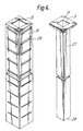
- Each stack 6 consists of a plurality of setting plates 7. As shown in the drawings, these plates have the shape of pyramids but they could be, for instance, cones. Each pyramid may consist solely of outwardly inclined surfaces in which event each is preferably a tight sliding fit over a composite duct 39 that can be a downwardly extending duct 18 that is closed at the end 19, as shown in Figure 4. However the pyramids or cones can have vertically extending necks 20 at their uppermost edges and these necks can slide over the duct 18 or they can inter-engage with each other so as to define the duct 18. The inter-engagement may be by means of, for instance, ribs 21 that clip over one another to hold the pyramids rigidly with respect to one another.
- Suspension flows down through the tank between the adjacent stacks and enters at the slot 22 between the lowermost edges of the lower part 23 of an adjacent pair of plates.
- the suspension flows upwardly between the inclined plates towards the upper part 24 and as it flows up between the plates solids tend to sediment on to the lower plate 7L while clarified liquor tends to rise up against the upper plate 7U.
- the cell between these plates is closed at its upper part 24 by a neck 20 or the pipe 18 but orifices 25 are provided in this upper part to allow the clarified water to escape from the cell into the central duct defined by the neck 20 or the pipe 18.
- Figure 3 shows a pyramidal duct of the same general construction as the ducts illustrated in Figure 2 except that a skirt 40 extends vertically downwards from the lowermost edge 41 of each of the pyramids.
- the vertical spacing between adjacent pyramids is defined by the vertical height of the neck 20 and the skirt 40 has a vertical dimension less than about 3/4 of the vertical spacing between the pyramids so as to ensure that the slot 23 that is defined between the lowermost edge 42 of the skirt and the lowermost edge of the next adjacent pyramid is at least about 1/4 of the vertical spacing between the pyramids. If the slot is too narrow then excessive mixing of the solids and the incoming suspension may occur.
- the vertical dimension of the skirt 40 is about half the vertical length of the neck 20.
- the top of the outer duct 18, or the duct defined by the necks 20 of the pyramids, is blanked off (for instance as at 19 in Figure 5) so that the flow through this duct has to be downwardly. If the duct is defined by pipe 18 then this is provided with orifices 26 in positions to match those of orifices 25.
- the area of the orifices can decrease downwardly, for instance the orifices at the top of Figure 3 are very much larger than the orifices at the bottom.
- the composite duct 39 is formed of a downflow collection pipe 18 or the vertical necks 20 and a co-axial, smaller, upflow duct 27 fitted in it.
- This duct is open at its lower end 28 so that the clarified water that flows downwardly along the annulus around duct 27 reverses its flow at the bottom 28 and flows upwardly through the duct 27 to the outlet 3, which is surrounded by a plate 19 that blanks off the top of the outer duct 18.
- the orifices are elongated slots extending over at least three quarters of the horizontal length of the plates at the positon of the orfices, i.e. at top part 24, thus promoting uniformity of flow.
- the composite duct 39 comprises a short downflow duct 31, leading at 32 into an inner coaxial upflow duct that has a narrow portion 33 and that leads into an upflow collection portion 34.
- the composite duct 39 has two short downflow ducts 35 and 36.
- the upflow duct consists of a narrow portion 37 leading into a wider portion 38 leading into a collection portion 34. This provides a particularly convenient way of obtaining different flow rates through different orifices even though the orifices are all of the same dimensions. Also, replacement of downflow ducts 31, or 35 and 36, by different ducts having different lengths or radii permits further variation in flow rates. Three or more short downflow ducts may be used if required.
- the tank 1 provided with the necessary inlets and outlets 2 to 5, and subsequently to install in the tank a plurality of settling assemblies, each consisting of a stack 6 of the settling plates mounted around a vertical collection duct.
- the vertical collection duct may be fitted previously in the chamber, in which event the plates are merely fitted over it, but it is often preferred that an assembly comprising part or all of the vertical collection duct and the stack should be preassembled and inserted into the chamber.
- the clarification apparatus used was substantially as shown in Figure 1, comprising a vertical rectangular tank having a height 2.13 metres and cross sectional area 0.21 m2 with a sedimentation conical zone positioned beneath the rectangular tank for collection and removal of settled solids. Feed and overflow launders were also fitted at the top of the tank and stacks of pyramids were arranged inside the tank.
- the central duct formed by each stack of pyramids had square cross sectional area, with the sides of the square base of the pyramids having length 15cm. The slope of the pyramids was 53° to the horizontal.
- the central collection duct was provided with slots, through which clarified water could escape.
- the apparatus was operated for a substantial period of time with a feed rate of 15m/hour (i.e., the volume of suspension for clarification entering the tank measured in m3 per hour per m2 of tank area).
- the suspension used for clarification was an aqueous solution of china clay particles with a solids content 580 mg per litre.
- the rate of delivery of clarified water from both pairs of stacks was about 15m/ hour and the solids content of the clarified water was found to be 35mg per litre for both pairs of stacks.
- the overflow of the clarified water was also at a rate of approximately 20m per hour.
- the resultant clarified liquid contained a solids content of 51mg per litre.
- the plant was operated at a flow rate for the suspension approximately 4 or 5 times a suitable flow rate in the absence of a stack, thus illustrating the benefit of the inclusion of the stack.
- the flow rates can be up to 10 or more times a suitable flow rate for an apparatus in which there are no stacks.
Landscapes
- Chemical & Material Sciences (AREA)
- Chemical Kinetics & Catalysis (AREA)
- Separation Using Semi-Permeable Membranes (AREA)
- Connector Housings Or Holding Contact Members (AREA)
- Manufacturing Of Electrical Connectors (AREA)
- Separation Of Suspended Particles By Flocculating Agents (AREA)
- Sewage (AREA)
- Separation By Low-Temperature Treatments (AREA)
- Amplifiers (AREA)
- Television Systems (AREA)
- Paper (AREA)
- Water Treatment By Sorption (AREA)
Applications Claiming Priority (2)
| Application Number | Priority Date | Filing Date | Title |
|---|---|---|---|
| GB8818866 | 1988-08-09 | ||
| GB888818866A GB8818866D0 (en) | 1988-08-09 | 1988-08-09 | Clarification apparatus |
Publications (3)
| Publication Number | Publication Date |
|---|---|
| EP0354744A2 true EP0354744A2 (de) | 1990-02-14 |
| EP0354744A3 EP0354744A3 (en) | 1990-05-16 |
| EP0354744B1 EP0354744B1 (de) | 1994-12-28 |
Family
ID=10641817
Family Applications (1)
| Application Number | Title | Priority Date | Filing Date |
|---|---|---|---|
| EP89308005A Expired - Lifetime EP0354744B1 (de) | 1988-08-09 | 1989-08-07 | Klärungsanlage |
Country Status (10)
| Country | Link |
|---|---|
| US (1) | US4988441A (de) |
| EP (1) | EP0354744B1 (de) |
| AT (1) | ATE116147T1 (de) |
| AU (1) | AU631559B2 (de) |
| DE (1) | DE68920232D1 (de) |
| DK (1) | DK387589A (de) |
| FI (1) | FI893762A7 (de) |
| GB (1) | GB8818866D0 (de) |
| NO (1) | NO893185L (de) |
| ZA (1) | ZA896038B (de) |
Families Citing this family (17)
| Publication number | Priority date | Publication date | Assignee | Title |
|---|---|---|---|---|
| US5474688A (en) * | 1993-09-29 | 1995-12-12 | Uop | Process for phase separation |
| US5340470A (en) * | 1993-09-29 | 1994-08-23 | Uop | Phase separator apparatus |
| AUPM714794A0 (en) * | 1994-07-29 | 1994-08-18 | International Fluid Separation Pty Limited | Separation apparatus and method |
| US6183634B1 (en) * | 1998-04-02 | 2001-02-06 | Bateman Process Equipment Limited | Separator |
| US6245243B1 (en) * | 1999-10-07 | 2001-06-12 | Meurer Industries, Inc. | Settler plate supports with integral outlets for individual flow channels and methods of collecting liquid from each flow channel |
| CA2417504A1 (en) * | 2000-07-25 | 2002-01-31 | Water Minerals Limited | Separators |
| US7718076B1 (en) | 2006-02-14 | 2010-05-18 | Charles Lonnie Meurer | Methods of and common gantry drive for single-pass cleaning of multiple stages of a material separation and removal system |
| US7314572B1 (en) | 2006-02-14 | 2008-01-01 | Meurer Research, Inc. | Methods of and apparatus for low-angle-tray settling with multi-zone configuration |
| US7780015B1 (en) | 2006-08-24 | 2010-08-24 | Meurer Research, Inc. | Methods of and sludge collector with adjacent opposed oppositely-moving blades for moving sludge in a basin |
| KR100732052B1 (ko) * | 2007-04-06 | 2007-06-25 | 이천억 | 유수부상 분리용 eip 팩 |
| US7560035B1 (en) | 2007-06-22 | 2009-07-14 | Charles Lonnie Meurer | Overhead trough with constant trough flow velocity configuration and methods of regulating trough flow velocity |
| US8173012B1 (en) * | 2010-09-17 | 2012-05-08 | Hue Nguyen Che | Marine oil leak recovery and marine petroleum mining method |
| IT1404151B1 (it) * | 2010-12-29 | 2013-11-15 | Eni Spa | Apparato di separazione per coalescenza di una miscela comprendente due fasi fluide tra loro immiscibili e di diversa densita' specifica |
| US10596492B2 (en) | 2014-07-09 | 2020-03-24 | Sudhin Biopharma | Particle settling devices |
| MY201619A (en) * | 2018-04-18 | 2024-03-06 | Sudhin Biopharma | Particle settling devices |
| US11433328B1 (en) * | 2019-09-11 | 2022-09-06 | Crescent Gdg Filter Venture, Llc | Non-discharge backwash filter system |
| AU2021236679B2 (en) | 2020-03-19 | 2024-02-15 | Sudhin Biopharma | Particle settling devices |
Family Cites Families (11)
| Publication number | Priority date | Publication date | Assignee | Title |
|---|---|---|---|---|
| US454487A (en) * | 1891-06-23 | Charles a | ||
| US635591A (en) * | 1899-05-01 | 1899-10-24 | Rasmus Rasmussen | Support for agricultural tools. |
| US879349A (en) * | 1907-04-24 | 1908-02-18 | James Worthington | Strain-distributing device for vehicles. |
| US2314977A (en) * | 1940-08-08 | 1943-03-30 | Infilce Inc | Liquid purification |
| US2570304A (en) * | 1946-05-17 | 1951-10-09 | Mirrlees Watson Company Ltd | Removing suspended solids from liquids |
| US2793186A (en) * | 1954-01-08 | 1957-05-21 | Ca Nat Research Council | Apparatus for classifying or settling fluid suspensions |
| GB879349A (en) * | 1959-02-13 | 1961-10-11 | Zd Y Na Vyrobu Vzduchotechnick | Improvements in or relating to settling tanks |
| CH428667A (de) * | 1962-12-07 | 1967-01-31 | Kralovopolska Strojirna Z Chem | Rektifizierapparat |
| US3306456A (en) * | 1964-09-16 | 1967-02-28 | Westinghouse Electric Corp | Settling apparatus |
| GB1344064A (en) * | 1970-07-01 | 1974-01-16 | Mirrlees Watson Co Ltd | Process and apparatus for the clarification of liquids |
| US4544487A (en) * | 1982-11-08 | 1985-10-01 | Bosnjak Milovan A | Clarifier/thickener |
-
1988
- 1988-08-09 GB GB888818866A patent/GB8818866D0/en active Pending
-
1989
- 1989-08-07 EP EP89308005A patent/EP0354744B1/de not_active Expired - Lifetime
- 1989-08-07 DE DE68920232T patent/DE68920232D1/de not_active Expired - Lifetime
- 1989-08-07 AT AT89308005T patent/ATE116147T1/de not_active IP Right Cessation
- 1989-08-08 AU AU39404/89A patent/AU631559B2/en not_active Ceased
- 1989-08-08 US US07/391,133 patent/US4988441A/en not_active Expired - Fee Related
- 1989-08-08 NO NO89893185A patent/NO893185L/no unknown
- 1989-08-08 ZA ZA896038A patent/ZA896038B/xx unknown
- 1989-08-08 DK DK387589A patent/DK387589A/da not_active Application Discontinuation
- 1989-08-09 FI FI893762A patent/FI893762A7/fi not_active IP Right Cessation
Also Published As
| Publication number | Publication date |
|---|---|
| NO893185D0 (no) | 1989-08-08 |
| FI893762A7 (fi) | 1990-02-10 |
| EP0354744A3 (en) | 1990-05-16 |
| FI893762A0 (fi) | 1989-08-09 |
| EP0354744B1 (de) | 1994-12-28 |
| ZA896038B (en) | 1990-05-30 |
| NO893185L (no) | 1990-02-12 |
| US4988441A (en) | 1991-01-29 |
| AU631559B2 (en) | 1992-12-03 |
| DK387589A (da) | 1990-02-10 |
| ATE116147T1 (de) | 1995-01-15 |
| GB8818866D0 (en) | 1988-09-14 |
| DE68920232D1 (de) | 1995-02-09 |
| DK387589D0 (da) | 1989-08-08 |
| AU3940489A (en) | 1990-02-15 |
Similar Documents
| Publication | Publication Date | Title |
|---|---|---|
| US4988441A (en) | Clarification apparatus | |
| US3813851A (en) | Process and apparatus for at least partly removing by gravity a particulate component from a liquid dispersion | |
| US9023216B2 (en) | Device for turbulence reduction | |
| US4346005A (en) | Tube settler module | |
| US3613889A (en) | Floating settler for separation of liquid and solid phases | |
| JP3331219B2 (ja) | 液体から不溶性粒子を分離する方法および装置 | |
| CA1040546A (en) | Perforate tube separator with depending lamellar thickener | |
| US4681683A (en) | Lamella gravity separator | |
| US4783255A (en) | Split countercurrent flow tube settler | |
| US2961099A (en) | Apparatus for separation of liquids or of solids from a liquid | |
| LT5160B (lt) | Suspensijos atskyrimo būdas, ypač skirtas nutekamųjų vandenų apdorojimui, ir įrenginys jo atlikimui | |
| US3891557A (en) | Peripheral feed clarification tank | |
| CN210114860U (zh) | 一种竖流式沉淀池 | |
| EP0258359B1 (de) | Verfahren zur trennung eines mediums in verschiedenartige komponenten durch schwerkraft | |
| CN207324181U (zh) | 竖流沉淀塔高效能中心管机构 | |
| EP0215862B1 (de) | Abscheidevorrichtung mit lamellen | |
| GB1602673A (en) | Apparatus for separating from each other the components of a mixture of water oil and dirt (sludge) | |
| US4515698A (en) | Liquid clarifying apparatus and methods | |
| EP0125306B1 (de) | Verbesserter aufklärer/verdicker | |
| CN201128742Y (zh) | 静态快速沉降器 | |
| EP0641585B1 (de) | Nachklärbecken | |
| KR100491353B1 (ko) | 고액분리장치 | |
| US7213712B2 (en) | System for settling solids or other impurities from water or wastewater and associated methods | |
| CN216403946U (zh) | 一种自循环连续流好氧颗粒污泥滤沉装置 | |
| EP0537221B1 (de) | Abschneider |
Legal Events
| Date | Code | Title | Description |
|---|---|---|---|
| PUAI | Public reference made under article 153(3) epc to a published international application that has entered the european phase |
Free format text: ORIGINAL CODE: 0009012 |
|
| AK | Designated contracting states |
Kind code of ref document: A2 Designated state(s): AT BE CH DE ES FR GB IT LI NL SE |
|
| PUAL | Search report despatched |
Free format text: ORIGINAL CODE: 0009013 |
|
| AK | Designated contracting states |
Kind code of ref document: A3 Designated state(s): AT BE CH DE ES FR GB IT LI NL SE |
|
| 17P | Request for examination filed |
Effective date: 19901109 |
|
| 17Q | First examination report despatched |
Effective date: 19920324 |
|
| GRAA | (expected) grant |
Free format text: ORIGINAL CODE: 0009210 |
|
| AK | Designated contracting states |
Kind code of ref document: B1 Designated state(s): AT BE CH DE ES FR GB IT LI NL SE |
|
| PG25 | Lapsed in a contracting state [announced via postgrant information from national office to epo] |
Ref country code: FR Effective date: 19941228 Ref country code: ES Free format text: THE PATENT HAS BEEN ANNULLED BY A DECISION OF A NATIONAL AUTHORITY Effective date: 19941228 Ref country code: LI Effective date: 19941228 Ref country code: NL Effective date: 19941228 Ref country code: CH Effective date: 19941228 Ref country code: BE Effective date: 19941228 Ref country code: AT Effective date: 19941228 Ref country code: IT Free format text: LAPSE BECAUSE OF FAILURE TO SUBMIT A TRANSLATION OF THE DESCRIPTION OR TO PAY THE FEE WITHIN THE PRE;WARNING: LAPSES OF ITALIAN PATENTS WITH EFFECTIVE DATE BEFORE 2007 MAY HAVE OCCURRED AT ANY TIME BEFORE 2007. THE CORRECT EFFECTIVE DATE MAY BE DIFFERENT FROM THE ONE RECORDED.SCRIBED TIME-LIMIT Effective date: 19941228 |
|
| REF | Corresponds to: |
Ref document number: 116147 Country of ref document: AT Date of ref document: 19950115 Kind code of ref document: T |
|
| REF | Corresponds to: |
Ref document number: 68920232 Country of ref document: DE Date of ref document: 19950209 |
|
| PG25 | Lapsed in a contracting state [announced via postgrant information from national office to epo] |
Ref country code: SE Effective date: 19950328 |
|
| PG25 | Lapsed in a contracting state [announced via postgrant information from national office to epo] |
Ref country code: DE Effective date: 19950329 |
|
| REG | Reference to a national code |
Ref country code: CH Ref legal event code: PL |
|
| EN | Fr: translation not filed | ||
| NLV1 | Nl: lapsed or annulled due to failure to fulfill the requirements of art. 29p and 29m of the patents act | ||
| PLBI | Opposition filed |
Free format text: ORIGINAL CODE: 0009260 |
|
| PLAB | Opposition data, opponent's data or that of the opponent's representative modified |
Free format text: ORIGINAL CODE: 0009299OPPO |
|
| 26 | Opposition filed |
Opponent name: SNF Effective date: 19950928 |
|
| R26 | Opposition filed (corrected) |
Opponent name: SNF Effective date: 19950928 |
|
| REG | Reference to a national code |
Ref country code: GB Ref legal event code: 732E |
|
| PLBF | Reply of patent proprietor to notice(s) of opposition |
Free format text: ORIGINAL CODE: EPIDOS OBSO |
|
| PLBL | Opposition procedure terminated |
Free format text: ORIGINAL CODE: EPIDOS OPPC |
|
| PLBM | Termination of opposition procedure: date of legal effect published |
Free format text: ORIGINAL CODE: 0009276 |
|
| D27C | Opposition proceedings terminated (deleted) | ||
| PLAD | Information related to termination of opposition procedure modified |
Free format text: ORIGINAL CODE: 0009299OPPC |
|
| STAA | Information on the status of an ep patent application or granted ep patent |
Free format text: STATUS: OPPOSITION PROCEDURE CLOSED |
|
| R27C | Opposition proceedings terminated (corrected) |
Effective date: 19960502 |
|
| PGFP | Annual fee paid to national office [announced via postgrant information from national office to epo] |
Ref country code: GB Payment date: 19970206 Year of fee payment: 8 |
|
| PG25 | Lapsed in a contracting state [announced via postgrant information from national office to epo] |
Ref country code: GB Free format text: LAPSE BECAUSE OF NON-PAYMENT OF DUE FEES Effective date: 19970807 |
|
| GBPC | Gb: european patent ceased through non-payment of renewal fee |
Effective date: 19970807 |
|
| RAP4 | Party data changed (patent owner data changed or rights of a patent transferred) |
Owner name: CIBA SPECIALTY CHEMICALS WATER TREATMENTS LIMITED |
|
| PLAB | Opposition data, opponent's data or that of the opponent's representative modified |
Free format text: ORIGINAL CODE: 0009299OPPO |