EP0354867A2 - Compresseur à volutes - Google Patents
Compresseur à volutes Download PDFInfo
- Publication number
- EP0354867A2 EP0354867A2 EP89730181A EP89730181A EP0354867A2 EP 0354867 A2 EP0354867 A2 EP 0354867A2 EP 89730181 A EP89730181 A EP 89730181A EP 89730181 A EP89730181 A EP 89730181A EP 0354867 A2 EP0354867 A2 EP 0354867A2
- Authority
- EP
- European Patent Office
- Prior art keywords
- compressor
- volume
- bypass
- capacity
- hole
- Prior art date
- Legal status (The legal status is an assumption and is not a legal conclusion. Google has not performed a legal analysis and makes no representation as to the accuracy of the status listed.)
- Granted
Links
- 230000006835 compression Effects 0.000 claims abstract description 22
- 238000007906 compression Methods 0.000 claims abstract description 22
- 239000012530 fluid Substances 0.000 claims abstract description 4
- 238000010586 diagram Methods 0.000 claims description 49
- 238000001816 cooling Methods 0.000 abstract description 16
- 230000004044 response Effects 0.000 abstract description 5
- 230000009471 action Effects 0.000 description 7
- 230000007246 mechanism Effects 0.000 description 7
- 230000001105 regulatory effect Effects 0.000 description 5
- 238000004378 air conditioning Methods 0.000 description 4
- 238000010276 construction Methods 0.000 description 3
- 230000000694 effects Effects 0.000 description 3
- 238000005461 lubrication Methods 0.000 description 3
- 238000007789 sealing Methods 0.000 description 3
- 230000008878 coupling Effects 0.000 description 2
- 238000010168 coupling process Methods 0.000 description 2
- 238000005859 coupling reaction Methods 0.000 description 2
- 230000009467 reduction Effects 0.000 description 2
- 239000003507 refrigerant Substances 0.000 description 2
- 230000002159 abnormal effect Effects 0.000 description 1
- 230000000903 blocking effect Effects 0.000 description 1
- 230000015556 catabolic process Effects 0.000 description 1
- 238000004891 communication Methods 0.000 description 1
- 230000003247 decreasing effect Effects 0.000 description 1
- 238000006731 degradation reaction Methods 0.000 description 1
- 230000002708 enhancing effect Effects 0.000 description 1
- 238000009434 installation Methods 0.000 description 1
- 230000000149 penetrating effect Effects 0.000 description 1
- 230000002265 prevention Effects 0.000 description 1
- 238000000926 separation method Methods 0.000 description 1
- 230000035939 shock Effects 0.000 description 1
Images


Classifications
-
- F—MECHANICAL ENGINEERING; LIGHTING; HEATING; WEAPONS; BLASTING
- F04—POSITIVE - DISPLACEMENT MACHINES FOR LIQUIDS; PUMPS FOR LIQUIDS OR ELASTIC FLUIDS
- F04C—ROTARY-PISTON, OR OSCILLATING-PISTON, POSITIVE-DISPLACEMENT MACHINES FOR LIQUIDS; ROTARY-PISTON, OR OSCILLATING-PISTON, POSITIVE-DISPLACEMENT PUMPS
- F04C28/00—Control of, monitoring of, or safety arrangements for, pumps or pumping installations specially adapted for elastic fluids
- F04C28/10—Control of, monitoring of, or safety arrangements for, pumps or pumping installations specially adapted for elastic fluids characterised by changing the positions of the inlet or outlet openings with respect to the working chamber
- F04C28/12—Control of, monitoring of, or safety arrangements for, pumps or pumping installations specially adapted for elastic fluids characterised by changing the positions of the inlet or outlet openings with respect to the working chamber using sliding valves
Definitions
- the present invention relates to a rotary compressor of such type as rotary vane, sliding vane, screw, scroll or the like.
- FIG. 10 is a vertical sectional diagram and FIG. 11 is a vertical sectional diagram as seen along the line XI-XI in FIG. 10.
- 10 is a housing which houses a power element A consisting of a motor rotor 09, a motor stator 08 and the like, and a compression element B consisting of a crankshaft 01, a roller 02, an upper bearing 03, a lower bearing 04, a cylinder 05, a diaphragm 06 (FIG. 11), a spring 07 (FIG.11) and the like.
- the crankshaft 01 is rotated by the motor stator 08 and the motor roller 09 to cause an eccentric motion in the roller 02, and sucks and compresses a gas by changing the volume of a compression space 05a.
- Sucked gas is brought into the compression space 05a through an accumulator 11, an inlet pipe 12 and an inlet space 31, changed to a high pressure gas by the compression action, and discharged to the outside of the housing 10 from a discharge pipe 18 through a discharge port 30, a discharge valve 15, a discharge valve hole 21, a discharge opening 22, and through a discharge muffler 20 and a discharge gas passage 17.
- lubrication oil is filled in the housing 10 to the neighborhood of the normal oil surface 19, rises within an oil pump 14 through a lubrication oil intake port 13, and lubricates the roller 02, the upper bearing 03, the lower bearing 04 and the like.
- the diaphragm 06 is immersed in the lubrication oil and carries out a reciprocating motion following the eccentric motion of the roller 02 so that it can be lubricated thoroughly.
- a frost prevention thermoswitch of the evaporator is actuated, and the compressor repeats turning on and off.
- problems such as lowering of the cool feeling due to variation in the blow-off temperature, increase of power due to raise in the torque at the time of starting, and generation of vibrations due to shocks at the time of starting and stopping of the compressor.
- a cylinder 32 is provided within the lower bearing 04, and the cylinder 32 is communicated via a bypass hole 33 to a portion of the compression space 05a, and also communicated via the bypass passage 34 to the inlet space 31.
- the bypass hole 33 and the bypass passage 34 are made communicable and interruptable by means of a piston 35 slidably fitted within the cylinder 32, and a compression spring 36 is interposed behind the piston 35 and the low pressure on the inlet side is introduced via a circuit 37 and an electro-magnetic valve 38 so as to control the capacity of the compressor.
- the compresser when the thermal load is large, the compresser can be operated at full output power by blocking the bypass hole 33 with the piston 35. Further, when the thermal load is reduced, the electromagnetic valve 38 is opened to move the piston 35 to the left of the figure, the refrigerant gas under compression is bypassed to the inlet space 31 side by communicating the bypass hole 33 and the bypass passage 34, and the number of times of turning on and off of the compressor is reduced by arranging the compressor output to match the load.
- the aforementioned problems can be improved to a large extent compared with the case of a compressor without capacity control.
- the following problems are generated in such a compressor. Namely, when the air conditioner is used throughout the four seasons, during the periods where the cooling capability is relatively unnecessary such as during the between season and the winter period, the output of the compressor becomes relatively large with cooling capability which is too large. This causes an intermittent operation of the compressor which sometimes results in the lowering of air-conditioning feeling. Further, when the compressor is operated at a high rotational frequency, similar phenomenon also takes place occasionally. In other words, with the conventional compressor there has been a problem that the range of capacity control is not sufficiently wide.
- the present invention was accomplished with the above in mind, and it is, therefore, the object of the invention to provide a rotary compressor which can resolve the above-mentioned problems, carrying out a continuous operation, and generating a suitable output in response to the load.
- the present invention has a constitution as characterized in (1) and (2) below.
- (1) The bypass hole is opened at a position of the revolving angle for which the compressed volume is in the range of zero to several percents of the volume of the compression space in the diagram representing the dependence of the compressed volume on the revolving angle, and the capacity of the compressor is made to be controllable in the range of 100 to substantially zero percent.
- a plurality of the bypass holes are provided along the direction of rotation, and at least one of them is opened at the position of the revolving angle for which the compressed volume is in the range of zero to several percents of the volume of the compression space in the diagram showing the dependence of the compressed volume on the revolving angle, and the capacity of the compressor is made to be controllable in the range of 100 to substantially zero percent.
- the bypass hole is provided at the position for which the flow rate of bypassing of a gas under compression from the compression space to the inlet space is appropriate in the compressed volume-revolving angle relation. Then, the opening and closing of the hole is controlled by the action of a piston operated via a control valve, and the capacity control is executed in the range of 0 to 100% or several to 100% of the actual discharge quantity of the compressor.
- the present invention can achieve the following effect.
- FIG. 1 is a sectional view of the rotary compressor which is a first embodiment of the present invention, a diagram corresponding to FIG. 11 of the prior art
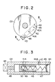
- FIG. 2 is a sectional diagram corresponding to the view along the line II-II in FIG. 10 of the prior art
- FIG. 3 is a sectional diagram along the line III-III in FIG. 2
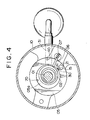
- FIG. 4 is a sectional view of the rotary compressor which is a second embodiment of the present invention
- FIG. 5 is a sectional view corresponding to FIG. 2
- FIG. 6 is a sectional view corresponding to FIG. 3
- FIG. 7 is a sectional view of a third embodiment of the rotary compressor in accordance with the present invention, a diagram corresponding to FIG. 1 or FIG. 4, FIG.
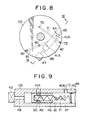
- FIG. 8 is a sectional diagram corresponding to FIG. 2 or FIG. 5
- FIG. 9 is a sectional diagram corresponding to FIG. 3 or FIG. 6
- FIG. 10 is a vertical sectional view of the prior art rotary compressor
- FIG. 11 is a sectional diagram as seen along the line XI-XI in FIG. 10
- FIG. 12 is a sectional view of the prior art rotary compressor equipped with a capacity control mechanism
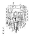
- FIG. 13 is a vertical sectional diagram showing a known scroll compressor
- FIG. 14 is a sectional view of the bypass passage of a prior art scroll compressor equipped with the capacity control mechanism
- FIG. 15 is a sectional view of the stationary scroll for the scroll compressor shown in FIG. 14, FIG.
- FIG. 16 is a diagram showing the volume (compressed volume) - revolving angle relation
- FIG. 17 is the volume-revolving angle relation diagram of a fourth embodiment of the present invention as applied to the scroll compressor
- FIG. 18 is a sectional diagram of a stationary scroll
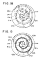
- FIG. 19 is a sectional diagram of the stationary scroll of a fifth embodiment of the present invention
- FIG. 20 is an enlarged diagram of the inner portion of the spiral element
- FIG. 21 is the volume-revolving angle diagram for a sixth embodiment of the present invention
- FIG. 22 is a sectional diagram of the stationary scroll of the above embodiment
- FIG. 23 is the volume-revolving angle diagram for a seventh embodiment of the present invention
- FIG. 24 is a sectional diagram the stationary scroll of the above embodiment.
- FIG. 1 to FIG. 9 show embodiments (the first to the third embodiments) of the present invention as applied to the sealed motor driven type rotary compressor.
- FIG. 1 is a sectional diagram of the first embodiment in the rotary compressor of the present invention which corresponds to FIG. 11 of the prior art compressor
- FIG. 2 is a sectional diagram corresponding to the sectional diagram as seen along the line II-II in FIG. 10 of the prior art compressor
- FIG. 3 is a sectional diagram viewed along the line III-III in FIG. 2.
- 40 is a hole provided in cylinder 05, and is communicated to an inlet space 31.
- Reference numeral 41 is a hole provided in the cylinder 05, and is communicated with a discharge port 30 in front of a discharge valve 15.
- a device consisting of an unloader piston hole 42, a control passage 48, a pressure control valve 43, a stiffening plate 45, a stopper ring, a piston 46 and a spring 47.
- Reference numeral 40A is a bypass cylinder communicated with the unloader piston hole 42, and is communicated with an input space via the cylinder hole 40.
- Reference numeral 41A is a bypass hole penetrating to the unloader piston hole 42, and is communicated with the discharge port 30 via the cylinder hole 41. Namely, a bypass passage is formed from the discharge port 30 to the inlet space 31 via the unloader piston hole 42.
- Reference numeral 43 is the pressure control valve, and the controlled pressure is applied to the piston 46 via the passage 48 to move the piston 46, and the bypass holes 40A and 41A are opened and closed.
- Reference numeral 49 is a circumferential groove provided in the piston 46, and 50 is a hole provided for communication with the unloader piston hole 42 (several of them may be formed depending upon the quantity for bypassing).
- Reference numeral 45 is a stiffening plate serving for both as stopper and seal for the piston 46 and the spring 47, and 44 is a fixing ring for fixing the stiffening plate 45 (installation of an O ring is desirable for the seal).
- FIG. 3 shows the condition in which the bypass passage which connects the front of the discharge valve to the inlet space is fully opened and the output is close to 0%.
- FIG. 4 is a sectional diagram of the rotary compressor in accordance with the second embodiment of the present invention, a diagram corresponding to FIG. 1, FIG. 5 is a sectional diagram corresponding to FIG. 2, and FIG. 6 is a sectional diagram corresponding to FIG. 3.
- 70 is a bypass hole at the position of volume of about 50%, which is provided in the upper bearing 03.
- the bypass hole 70 is provided at the position of revolving angle of the roller for which the compressed volume, in the relationship of the roller revolving angle relative to the compressed volume of the compressor (referred to simply as volume-revolving angle relation hereinafter), is 50%.
- a bypass hole passage 71 is provided so as to communicate the bypass hole 70 with the unloader piston hole 42.
- Reference numeral 72 is a sealing plug.
- the construction other than the above is similar to the first embodiment.
- the bypass passage is constructed as shown in FIGS. 4 and 5 so that at the start of capacity control the compressed gas is first bypassed to the inlet space by the opening of the hole at the position of volume of about 50% caused by the motion of the piston. As the piston moves further, the bypass passage in front of the discharge valve is opened to the inlet space, increasing further the rate of capacity control.
- FIG. 6 shows the condition in which the output is close to 0% as a result of full opening by the piston of the bypass passage 41A in front of the discharge valve and the hole 70 at the position of volume of about 50%.
- FIG. 7 is a sectional diagram of the rotary compressor in accordance with the third embodiment of the present invention, a diagram corresponding to FIG. 1 or FIG. 4, FIG. 8 is a sectional diagram corresponding to FIG. 2 or FIG. 5, and FIG. 9 is a sectional diagram corresponding to FIG. 3 or FIG. 6.
- Reference numeral 80 is a bypass hole at the position of volume of about 30%, provided in the upper bearing 03. Further, a bypass hole passage 81 is provided so as to communicate the bypass hole 80 with the unloader piston hole 42.
- Reference numeral 82 is a sealing plug. The construction other than the above is similar to the second embodiment.
- the present embodiment is to assure the action of the second embodiment described above.
- the bypass passage as shown in FIGS. 7 and 8
- the hole at the position of volume of about 50% is first opened to be bypassed by the piston to the inlet space.
- the hole at the position of volume of about 30% is opened to be bypassed to the inlet space.
- the bypass passage in front of the discharge valve is opened to the inlet space, and the rate of output control is further enhanced.
- FIG. 9 there is shown the condition of output of close to 0% in which the hole at the position of volume of about 50%, the hole at the position of volume of about 30% and the bypass passage in front of the discharge valve are fully opened by the piston.
- FIG. 13 is a vertical sectional diagram of the scroll compressor in which the compressor main body 001 consists of a front case 011, a front nose 012 and a housing 013.
- a main bearing 021 is provided at about the center of the front case 011, an auxiliary bearing 022 is provided in the front nose 012, and a main bearing 003 is supported rotatably by these bearings.
- a stationary scroll 004 and a revolving scroll 005 are arranged within the housing 013, and the stationary scroll 004 is fixed integrally in the housing 013 with a bolt 014.
- the stationary scroll 004 consists of an approximately disk-shaped end plate 041 and a spiral element 042.
- the revolving scroll 005 On the tip of the spiral element 042 there is mounted a tip seal 043 to give a better sealing, and a discharge port 044 is provided at about the central part of the end plate 041.
- the revolving scroll 005 has an approximately disk-shaped end plate 051, a spiral element 052, and a boss 053 provided protruding in the end plate 051.
- a revolving bearing 023 for moving the revolving scroll 005 is installed within the boss 053, and a tip seal 054 is mounted on the tip of the spiral element 052 similar to the case of stationary scroll 004.
- the main shaft 003 has a balance weight 031 and a drive bush 032, and the drive bush 032 is supported rotatably by the revolving bearing 023 of the revolving scroll 005.
- the front case 011 there is constructed a ball coupling which inhibits the rotation and permits the revolution of the revolving scroll 005 and receives a thrust force of the resolving scroll 005.
- Sealed small spaces 055, 056 and 057 are formed by engaging the spiral element 052 of the revolving scroll 005 with the spiral element 042 of the stationary scroll 004, with the phase of 180° between the spiral elements.
- the revolving scroll 005 is driven via the drive bush 032.
- the revolving scroll 005 revolves around the stationary scroll 004 without rotation by means of the ball coupling 026.
- the contact point of the spiral elements 042 and 052 moves from the outside toward inside of the spirals.
- the sealed small spaces 055, 056 and 057 formed by the engagement of the scrolls 004 and 005 are moved toward the center of the spirals 042 and 052 while reducing their volumes.
- a referigerant gas sucked into an inlet chamber (not shown) from an external heat exchanger (not shown) or the like is sucked into the sealed small space 005 from a spiral outer end opening 058 of the spiral elements 042 and 052, compressed under the volume changes in the sealed small spaces 055, 056 and 057. Then, the gas moves successivelysively toward the centers of the spiral elements 052 and 042, discharged to a discharge chamber 045 from the discharge port 044 provided on the end plate 041 of the stationary scroll 004, and is sent to the outside of the compressor main body 001 from the discharge chamber 045.
- FIG. 14 is a vertical sectional diagram which is partially different from the vertical sectional diagram shown in FIG. 13) as shown in FIG.
- First bypass holes 121a and 121b and second bypass holes 122a and 122b are provided to be opened to sealed small spaces 111 and 112, respectively, facing the end plate 041 of the stationary scroll 004.
- pistons 130a and 130b that open and close the pairs of the first and the second bypass holes 121a, 122a and 121b and 122b.
- the piston 130a is internally equipped with a spring 131a, and the piston is constructed so as to receive a working pressure from a pressure control valve 132 on the other end of the piston 101.
- the bypass holes 121a and 122a are opened by moving the piston 130a by means of the spring 131a, and the refrigerant gas is led from the sealed small spaces 111 and 112 to the bypass passage 123 via the bypass holes 121a and 122a to be led to the spiral outer end opening 058 or the inlet chamber (not shown), as may be understood by referring to FIG. 14.
- the first bypass holes 121a and 121b and the second bypass holes 122a and 122b are ordinarily provided, as indicated in the volume-revolving angle relation shown in FIG.
- the curve shown in FIG. 16 corresponds to the case where the top clearance volume that is generated from the revolving angle at which the two scrolls start to be separated at the central parts is neglected.
- the range of capacity control is not wide enough, similar to the case of the rotary compressor, so that there has been a problem that the air conditioning feeling is spoiled due to intermittent operation of the compressor.
- FIG. 17 is a diagram showing the volume-revoling angle relation for the fourth embodiment of the present invention, that is, a diagram showing the relation between the compressed volume of the compression space and the revolving angle of the revolving scroll
- FIG. 18 is a sectional diagram of the stationary scroll of the above embodiment.
- 004 is a stationary scroll which is composed of an end plate 041 and a spiral element 042 similar to the conventional device
- first bypass holes 121a and 121b are provided analogous to the conventional device. It is desirable to determine the range of opening of the first bypass holes 121a and 121b so as to cover, including the case of volume of 100%, the lower volume percent region in the diagram for the volume-revolving angle relation.
- Second bypass holes 211a and 211b are provided in such a way that one end of the respective holes is opened to a discharge port 044, and the other end of the respective holes is provided on an end plate 041 of the stationary scroll 004 so as to be opened to a bypass passage 123a or 123b that is opened and closed by a piston (not shown).
- Components other than those mentioned above, namely, the piston, spring, bypass holes 123a and 123b, and pressure control valve are installed in the same way as in the conventional capacity control mechanism.
- the range of the revolving angle of the revolving scroll for which the bypass holes are opened can be made to cover the range of 100-0% of the compressed volume, so that it becomes possible to increase markedly the capacity control range of the conventional capacity control mechanism. That is, by increasing the capacity control range the cooling capability at the time of capacity control, even during the between season, winter season and the like, is decreased substantially, so that there will be no cooling capability generated that is more than what is necessary. As a result, the compressor can be operated continuously and degradation of the air conditioning feeling due to intermittent operation of the compressor can be avoided. It should be noted that the situation is analogous at the time of fast operation of the compressor.
- bypass holes at the position of compress value 0% are opened at the discharge port.
- second bypass holes 511a and 511b are provided in the regions that are on the inner side of the spiral element than the marginal points that are determined by the marginal angle for defining a due involute curve of the spiral element. In this case, capacity control in the range of 100-0% becomes also possible similar to the fourth embodiment.
- FIG. 20 is an enlarged diagram of the inner end portion of the spiral element, and the way of determining its profile is shown, for example, in Japanese Patent Application, No. 62-17074.
- the points B and E in the drawing represent the marginal points determined by the angle ⁇ of the marginal angle for defining a due involute curve.
- a small clearance A for avoiding abnormal collision with the revolving scroll. Because of this, engagement between both scrolls begins to be separated in the region on the inner side of the points B and E. If the top clearance volume that is generated by the separation of both scrolls in the inner central portion is neglected in the diagram for the volume-revolving angle relation, the compressed volume at the points B and E will become 0%.
- FIG. 21 and FIG. 22 representing the sixth embodiment shows an example in which the capacity control is arranged to cover the compressed volume in the range of 100 to several percents.
- FIG. 22 shows a sectional diagram of the stationary scroll of the present embodiment.
- Reference numerals 311a and 311b are bypass holes at the position of volume of about several percents provided in place of 511a and 511b of the fifth embodiment, and the remaining constitution of the embodiment is similar to the case of the fifth embodiment.
- the effect realizable is the same as the fifth embodiment.
- FIG. 23 is a diagram showing the volume-revolving angle relation in accordance with the seventh embodiment of the present invention and FIG. 24 is a sectional diagram of the stationary scroll of the present embodiment.
- This embodiment is provided with three pairs fo bypass holes.
- Reference numerals 410a and 410b are first bypass holes
- 411a and 411b are second bypass holes provided at the position of volume of about 30%
- 412a and 412b are third bypass holes.
- the remaining portion is the same as the sixth embodiment.
- the embodiment characterized in that it can realize an effect of finer capacity control.
- the first embodiment is an example in which a bypass passage is provided from the discharge port to the inlet space, a capacity control valve (pressure control valve) is installed in a part of the bypass passage, and the discharge quantity of the compressor is controlled in the range of 0-100% by means of the opening of the capacity control valve.
- a capacity control valve pressure control valve
- the second embodiment is an example in which a bypass hole is provided at the position of capacity of about 50%, in series to the bypass hole of the first embodiment, and the discharge quantity of the compressor is controlled to be in the range of 0-100% by regulating the opening of the capacity control valve.
- the third embodiment is an example in which a bypass hole is provided at the position of capacity of about 30%, in series to those of the second embodiment, and the discharge quantity of the compressor is controlled to be in the range of 0-100% by regulating the opening of the capacity control valve.
- the fourth embodiment and the fifth embodiments are examples in which, on the assumption that the volume at the time of intake shutoff is 100% and that at the time of discharge completion is 0% in the diagram showing the volume-revolving angle relation of the compressor, bypass holes are provided at the discharge port or within marginal points determined by a marginal angle for defining a due involute curve, bypass passages are provided leading from the bypass holes to the inlet space, a capacity control valve is installed in a portion of a bypass passages, and the discharge quantity of the compressor is controlled in the range of 0-100% by regulating the opening of the capacity control valve.
- the sixth embodiment is an example in which the position of the bypass hole for volume of 0% is provided at a position for volume of several percents which is somewhat on the outside of that of 0%, and the discharge quantity of the compressor is controlled in the range of several to 100% by regulating the opening of the capacity control valve.
- the seventh embodiment is an example in which a bypass hole at the volume position of about 30% in series to those of the sixth embodiment, and the discharge quantity is controlled in the range of several to 100% by regulating the opening of the capacity control valve.
Landscapes
- Engineering & Computer Science (AREA)
- Mechanical Engineering (AREA)
- General Engineering & Computer Science (AREA)
- Applications Or Details Of Rotary Compressors (AREA)
- Rotary Pumps (AREA)
Applications Claiming Priority (2)
| Application Number | Priority Date | Filing Date | Title |
|---|---|---|---|
| JP63199998A JPH0794832B2 (ja) | 1988-08-12 | 1988-08-12 | 回転式圧縮機 |
| JP199998/88 | 1988-08-12 |
Related Child Applications (1)
| Application Number | Title | Priority Date | Filing Date |
|---|---|---|---|
| EP92250107.7 Division-Into | 1992-05-05 |
Publications (3)
| Publication Number | Publication Date |
|---|---|
| EP0354867A2 true EP0354867A2 (fr) | 1990-02-14 |
| EP0354867A3 EP0354867A3 (en) | 1990-05-30 |
| EP0354867B1 EP0354867B1 (fr) | 1994-05-11 |
Family
ID=16417100
Family Applications (2)
| Application Number | Title | Priority Date | Filing Date |
|---|---|---|---|
| EP19920250107 Withdrawn EP0519580A3 (en) | 1988-08-12 | 1989-08-03 | Rotary compressor |
| EP89730181A Expired - Lifetime EP0354867B1 (fr) | 1988-08-12 | 1989-08-03 | Compresseur à volutes |
Family Applications Before (1)
| Application Number | Title | Priority Date | Filing Date |
|---|---|---|---|
| EP19920250107 Withdrawn EP0519580A3 (en) | 1988-08-12 | 1989-08-03 | Rotary compressor |
Country Status (7)
| Country | Link |
|---|---|
| US (2) | US5074760A (fr) |
| EP (2) | EP0519580A3 (fr) |
| JP (1) | JPH0794832B2 (fr) |
| CN (1) | CN1014346B (fr) |
| AU (2) | AU619876B2 (fr) |
| CA (1) | CA1330430C (fr) |
| DE (1) | DE68915224T2 (fr) |
Cited By (11)
| Publication number | Priority date | Publication date | Assignee | Title |
|---|---|---|---|---|
| EP0486122A1 (fr) * | 1990-11-16 | 1992-05-20 | Mitsubishi Jukogyo Kabushiki Kaisha | Compresseur du type à volutes |
| EP0486121A1 (fr) * | 1990-11-14 | 1992-05-20 | Mitsubishi Jukogyo Kabushiki Kaisha | Compresseur du type à volutes |
| EP0486120A1 (fr) * | 1990-11-14 | 1992-05-20 | Mitsubishi Jukogyo Kabushiki Kaisha | Compresseur du type à volutes |
| EP0555945A1 (fr) * | 1992-02-06 | 1993-08-18 | Mitsubishi Jukogyo Kabushiki Kaisha | Dispositif de contrôle de capacité pour compresseur à volutes |
| EP0809032A1 (fr) * | 1996-05-21 | 1997-11-26 | Sanden Corporation | Compresseur à spirales avec dispositif de variation de la capacité |
| WO2004094829A1 (fr) * | 2003-04-19 | 2004-11-04 | Lg Electronics Inc. | Compresseur du type rotatif |
| WO2006014086A1 (fr) * | 2004-08-06 | 2006-02-09 | Lg Electronics Inc. | Compresseur tournant de type à capacité variable et méthode de fonctionnement correspondante |
| WO2006014083A1 (fr) * | 2004-08-06 | 2006-02-09 | Lg Electronics Inc. | Compresseur tournant de type à capacité variable, méthode de fonctionnement correspondante et méthode pour climatiseur avec compresseur |
| WO2006014079A1 (fr) * | 2004-08-06 | 2006-02-09 | Lg Electronics Inc. | Compresseur rotatif à cylindrée variable et méthode d’utilisation s’y rapportant |
| EP1657443A1 (fr) * | 2004-11-12 | 2006-05-17 | LG Electronics Inc. | Compresseur à spirales |
| EP1696125A1 (fr) * | 2005-01-27 | 2006-08-30 | LG Electronics Inc. | Système d'air conditionné à capacité variable |
Families Citing this family (91)
| Publication number | Priority date | Publication date | Assignee | Title |
|---|---|---|---|---|
| US5451146A (en) * | 1992-04-01 | 1995-09-19 | Nippondenso Co., Ltd. | Scroll-type variable-capacity compressor with bypass valve |
| US5224839A (en) * | 1992-04-15 | 1993-07-06 | Hydraulic Concepts | Variable delivery pump |
| CN1056214C (zh) * | 1993-11-19 | 2000-09-06 | 倪诗茂 | 容积可调且压缩比优化的涡卷容积式流体压缩装置 |
| US5607288A (en) * | 1993-11-29 | 1997-03-04 | Copeland Corporation | Scroll machine with reverse rotation protection |
| US5803716A (en) * | 1993-11-29 | 1998-09-08 | Copeland Corporation | Scroll machine with reverse rotation protection |
| US5591014A (en) * | 1993-11-29 | 1997-01-07 | Copeland Corporation | Scroll machine with reverse rotation protection |
| JP3376692B2 (ja) * | 1994-05-30 | 2003-02-10 | 株式会社日本自動車部品総合研究所 | スクロール型圧縮機 |
| JP3376729B2 (ja) * | 1994-06-08 | 2003-02-10 | 株式会社日本自動車部品総合研究所 | スクロール型圧縮機 |
| US5678985A (en) * | 1995-12-19 | 1997-10-21 | Copeland Corporation | Scroll machine with capacity modulation |
| JP3723283B2 (ja) * | 1996-06-25 | 2005-12-07 | サンデン株式会社 | スクロール型可変容量圧縮機 |
| US5800141A (en) * | 1996-11-21 | 1998-09-01 | Copeland Corporation | Scroll machine with reverse rotation protection |
| JPH1182334A (ja) * | 1997-09-09 | 1999-03-26 | Sanden Corp | スクロール型圧縮機 |
| US6123517A (en) * | 1997-11-24 | 2000-09-26 | Copeland Corporation | Scroll machine with capacity modulation |
| US6120255A (en) * | 1998-01-16 | 2000-09-19 | Copeland Corporation | Scroll machine with capacity modulation |
| US6116867A (en) * | 1998-01-16 | 2000-09-12 | Copeland Corporation | Scroll machine with capacity modulation |
| US6089830A (en) * | 1998-02-02 | 2000-07-18 | Ford Global Technologies, Inc. | Multi-stage compressor with continuous capacity control |
| US6079952A (en) * | 1998-02-02 | 2000-06-27 | Ford Global Technologies, Inc. | Continuous capacity control for a multi-stage compressor |
| KR100285846B1 (ko) * | 1998-05-08 | 2001-04-16 | 윤종용 | 밀폐형회전압축기 |
| US6290472B2 (en) | 1998-06-10 | 2001-09-18 | Tecumseh Products Company | Rotary compressor with vane body immersed in lubricating fluid |
| US6120272A (en) * | 1998-08-10 | 2000-09-19 | Gallardo; Arturo | Pump-motor for fluid with elliptical members |
| US6176686B1 (en) | 1999-02-19 | 2001-01-23 | Copeland Corporation | Scroll machine with capacity modulation |
| KR100311994B1 (ko) * | 1999-06-11 | 2001-11-03 | 가나이 쓰토무 | 회전 압축기 |
| US6267565B1 (en) | 1999-08-25 | 2001-07-31 | Copeland Corporation | Scroll temperature protection |
| US6293767B1 (en) | 2000-02-28 | 2001-09-25 | Copeland Corporation | Scroll machine with asymmetrical bleed hole |
| US6464467B2 (en) * | 2000-03-31 | 2002-10-15 | Battelle Memorial Institute | Involute spiral wrap device |
| US6412293B1 (en) | 2000-10-11 | 2002-07-02 | Copeland Corporation | Scroll machine with continuous capacity modulation |
| US6679683B2 (en) | 2000-10-16 | 2004-01-20 | Copeland Corporation | Dual volume-ratio scroll machine |
| US6419457B1 (en) | 2000-10-16 | 2002-07-16 | Copeland Corporation | Dual volume-ratio scroll machine |
| FR2830291B1 (fr) * | 2001-09-28 | 2004-04-16 | Danfoss Maneurop S A | Compresseur a spirales, de capacite variable |
| US6821092B1 (en) | 2003-07-15 | 2004-11-23 | Copeland Corporation | Capacity modulated scroll compressor |
| CN100424355C (zh) * | 2004-06-21 | 2008-10-08 | 乐金电子(天津)电器有限公司 | 旋转式压缩机的排出阀装置 |
| US8425204B2 (en) * | 2004-06-24 | 2013-04-23 | Luk Automobiltechnik Gmbh & Co. Kg | Pump |
| JP2008506885A (ja) | 2004-07-13 | 2008-03-06 | タイアックス エルエルシー | 冷凍システムおよび冷凍方法 |
| KR100629872B1 (ko) | 2004-08-06 | 2006-09-29 | 엘지전자 주식회사 | 로터리 압축기의 용량 가변 장치 및 이를 구비한 에어콘의운전 방법 |
| JP2006177194A (ja) * | 2004-12-21 | 2006-07-06 | Sanyo Electric Co Ltd | 多気筒回転圧縮機 |
| JP2006300048A (ja) * | 2005-03-24 | 2006-11-02 | Matsushita Electric Ind Co Ltd | 密閉型圧縮機 |
| US20070036661A1 (en) * | 2005-08-12 | 2007-02-15 | Copeland Corporation | Capacity modulated scroll compressor |
| US9404499B2 (en) * | 2006-12-01 | 2016-08-02 | Emerson Climate Technologies, Inc. | Dual chamber discharge muffler |
| US8057194B2 (en) * | 2006-12-01 | 2011-11-15 | Emerson Climate Technologies, Inc. | Compressor with discharge muffler attachment using a spacer |
| US7547202B2 (en) * | 2006-12-08 | 2009-06-16 | Emerson Climate Technologies, Inc. | Scroll compressor with capacity modulation |
| US20090071183A1 (en) * | 2007-07-02 | 2009-03-19 | Christopher Stover | Capacity modulated compressor |
| US7811071B2 (en) | 2007-10-24 | 2010-10-12 | Emerson Climate Technologies, Inc. | Scroll compressor for carbon dioxide refrigerant |
| KR101192642B1 (ko) * | 2008-05-30 | 2012-10-18 | 에머슨 클리메이트 테크놀로지즈 인코퍼레이티드 | 용량조절 시스템을 가진 압축기 |
| US7976295B2 (en) * | 2008-05-30 | 2011-07-12 | Emerson Climate Technologies, Inc. | Compressor having capacity modulation system |
| US7972125B2 (en) * | 2008-05-30 | 2011-07-05 | Emerson Climate Technologies, Inc. | Compressor having output adjustment assembly including piston actuation |
| CN102076963B (zh) * | 2008-05-30 | 2013-09-18 | 艾默生环境优化技术有限公司 | 一种具有容量调节系统的压缩机 |
| ES2647783T3 (es) * | 2008-05-30 | 2017-12-26 | Emerson Climate Technologies, Inc. | Compresor que tiene un sistema de modulación de la capacidad |
| JP5360709B2 (ja) * | 2008-08-29 | 2013-12-04 | 東芝キヤリア株式会社 | 密閉型圧縮機と冷凍サイクル装置 |
| WO2010024409A1 (fr) * | 2008-08-29 | 2010-03-04 | 東芝キヤリア株式会社 | Compresseur clos, compresseur rotatif à deux cylindres, et appareil à cycle frigorifique |
| CN102132046B (zh) * | 2008-08-29 | 2014-08-06 | 东芝开利株式会社 | 密闭型压缩机、双汽缸旋转式压缩机和制冷循环装置 |
| US7976296B2 (en) * | 2008-12-03 | 2011-07-12 | Emerson Climate Technologies, Inc. | Scroll compressor having capacity modulation system |
| US7988433B2 (en) | 2009-04-07 | 2011-08-02 | Emerson Climate Technologies, Inc. | Compressor having capacity modulation assembly |
| US8568118B2 (en) * | 2009-05-29 | 2013-10-29 | Emerson Climate Technologies, Inc. | Compressor having piston assembly |
| US8616014B2 (en) | 2009-05-29 | 2013-12-31 | Emerson Climate Technologies, Inc. | Compressor having capacity modulation or fluid injection systems |
| CN101691863B (zh) * | 2009-09-24 | 2012-02-01 | 珠海格力电器股份有限公司 | 一种降耗变排量回转压缩机 |
| US8517703B2 (en) * | 2010-02-23 | 2013-08-27 | Emerson Climate Technologies, Inc. | Compressor including valve assembly |
| US8794941B2 (en) | 2010-08-30 | 2014-08-05 | Oscomp Systems Inc. | Compressor with liquid injection cooling |
| US9267504B2 (en) | 2010-08-30 | 2016-02-23 | Hicor Technologies, Inc. | Compressor with liquid injection cooling |
| JP2012097677A (ja) * | 2010-11-03 | 2012-05-24 | Denso Corp | 可変容量式スクロール型圧縮機 |
| CN201916158U (zh) * | 2010-12-17 | 2011-08-03 | 靳北彪 | 回流式高效气体压缩机 |
| CN102734165A (zh) * | 2011-04-11 | 2012-10-17 | 广东美芝制冷设备有限公司 | 容量控制式旋转压缩机 |
| CN103185007B (zh) * | 2011-12-29 | 2015-11-04 | 珠海格力节能环保制冷技术研究中心有限公司 | 旋转压缩机的气缸、旋转压缩机及空调器 |
| US9249802B2 (en) | 2012-11-15 | 2016-02-02 | Emerson Climate Technologies, Inc. | Compressor |
| US9651043B2 (en) | 2012-11-15 | 2017-05-16 | Emerson Climate Technologies, Inc. | Compressor valve system and assembly |
| US9127677B2 (en) | 2012-11-30 | 2015-09-08 | Emerson Climate Technologies, Inc. | Compressor with capacity modulation and variable volume ratio |
| US9435340B2 (en) | 2012-11-30 | 2016-09-06 | Emerson Climate Technologies, Inc. | Scroll compressor with variable volume ratio port in orbiting scroll |
| JP5459384B2 (ja) * | 2012-12-26 | 2014-04-02 | 株式会社デンソー | 可変容量式スクロール型圧縮機 |
| US9739277B2 (en) | 2014-05-15 | 2017-08-22 | Emerson Climate Technologies, Inc. | Capacity-modulated scroll compressor |
| US9989057B2 (en) | 2014-06-03 | 2018-06-05 | Emerson Climate Technologies, Inc. | Variable volume ratio scroll compressor |
| US9790940B2 (en) | 2015-03-19 | 2017-10-17 | Emerson Climate Technologies, Inc. | Variable volume ratio compressor |
| US10378540B2 (en) | 2015-07-01 | 2019-08-13 | Emerson Climate Technologies, Inc. | Compressor with thermally-responsive modulation system |
| CN207377799U (zh) | 2015-10-29 | 2018-05-18 | 艾默生环境优化技术有限公司 | 压缩机 |
| JP6446542B2 (ja) * | 2016-02-02 | 2018-12-26 | クワントン メイヂー コンプレッサー カンパニー リミテッド | 可変容量型圧縮機及びこれを備える冷凍装置 |
| US10890186B2 (en) | 2016-09-08 | 2021-01-12 | Emerson Climate Technologies, Inc. | Compressor |
| US10801495B2 (en) | 2016-09-08 | 2020-10-13 | Emerson Climate Technologies, Inc. | Oil flow through the bearings of a scroll compressor |
| US10753352B2 (en) | 2017-02-07 | 2020-08-25 | Emerson Climate Technologies, Inc. | Compressor discharge valve assembly |
| CN107237750A (zh) * | 2017-07-14 | 2017-10-10 | 珠海格力节能环保制冷技术研究中心有限公司 | 泵体组件、流体机械及换热设备 |
| US11022119B2 (en) | 2017-10-03 | 2021-06-01 | Emerson Climate Technologies, Inc. | Variable volume ratio compressor |
| US10962008B2 (en) | 2017-12-15 | 2021-03-30 | Emerson Climate Technologies, Inc. | Variable volume ratio compressor |
| US10995753B2 (en) | 2018-05-17 | 2021-05-04 | Emerson Climate Technologies, Inc. | Compressor having capacity modulation assembly |
| US11656003B2 (en) | 2019-03-11 | 2023-05-23 | Emerson Climate Technologies, Inc. | Climate-control system having valve assembly |
| CN111734635A (zh) * | 2020-07-31 | 2020-10-02 | 珠海凌达压缩机有限公司 | 一种泵体组件及转子压缩机 |
| US11655813B2 (en) | 2021-07-29 | 2023-05-23 | Emerson Climate Technologies, Inc. | Compressor modulation system with multi-way valve |
| US12259163B2 (en) | 2022-06-01 | 2025-03-25 | Copeland Lp | Climate-control system with thermal storage |
| US11846287B1 (en) | 2022-08-11 | 2023-12-19 | Copeland Lp | Scroll compressor with center hub |
| US11965507B1 (en) | 2022-12-15 | 2024-04-23 | Copeland Lp | Compressor and valve assembly |
| US12416308B2 (en) | 2022-12-28 | 2025-09-16 | Copeland Lp | Compressor with shutdown assembly |
| US12173708B1 (en) | 2023-12-07 | 2024-12-24 | Copeland Lp | Heat pump systems with capacity modulation |
| US12163523B1 (en) | 2023-12-15 | 2024-12-10 | Copeland Lp | Compressor and valve assembly |
| US12523223B1 (en) * | 2024-09-19 | 2026-01-13 | Mahle International Gmbh | Balanced rolling piston compressor with central mass reductions for improved compressor stability |
| US12320354B1 (en) * | 2024-09-19 | 2025-06-03 | Mahle International Gmbh | Compression device having integrated discharge chamber(s) and compressor with compression device having integrated discharge chamber(s) |
Family Cites Families (24)
| Publication number | Priority date | Publication date | Assignee | Title |
|---|---|---|---|---|
| FR480617A (fr) * | 1915-01-05 | 1916-08-31 | Societe Suisse Pour La Construction De Locomotives | Procédé et dispositif pour la régulation automatique de la dépense de force motrice aux compresseurs d'air rotatifs à compartiments d'aspiration et de compression multiples |
| DE608848C (de) * | 1932-02-10 | 1935-02-01 | Robert Bosch Akt Ges | Verdichter mit rotierendem Kolben |
| FR1035238A (fr) * | 1950-04-13 | 1953-08-19 | Sulzer Ag | Compresseur à piston rotatif |
| FR1303685A (fr) * | 1961-08-23 | 1962-09-14 | Studia Technica Ets | Machine rotative |
| US3224662A (en) * | 1965-02-16 | 1965-12-21 | Oldberg Oscar | Compressor modulating system |
| US3451614A (en) * | 1967-06-14 | 1969-06-24 | Frick Co | Capacity control means for rotary compressors |
| US4022551A (en) * | 1972-06-13 | 1977-05-10 | Aikoh Co., Ltd. | Variable capacity type gear pump |
| US3767328A (en) * | 1972-07-19 | 1973-10-23 | Gen Electric | Rotary compressor with capacity modulation |
| JPS5428002A (en) * | 1977-08-03 | 1979-03-02 | Hitachi Ltd | Control system for scrool fluid machine |
| US4389171A (en) * | 1981-01-15 | 1983-06-21 | The Trane Company | Gas compressor of the scroll type having reduced starting torque |
| US4514150A (en) * | 1981-03-09 | 1985-04-30 | Sanden Corporation | Scroll type compressor with displacement adjusting mechanism |
| JPS58122386A (ja) * | 1982-01-13 | 1983-07-21 | Hitachi Ltd | スクロ−ル圧縮機 |
| JPS5928083A (ja) * | 1982-08-07 | 1984-02-14 | Sanden Corp | スクロ−ル型圧縮機 |
| EP0113786A1 (fr) * | 1982-12-15 | 1984-07-25 | Sanden Corporation | Compresseur à volutes imbriquées avec mécanimsme de contrôle du débit |
| JPS59119080A (ja) * | 1982-12-24 | 1984-07-10 | Hitachi Ltd | スクロ−ル圧縮機 |
| JPS601397A (ja) * | 1983-06-17 | 1985-01-07 | Toyoda Autom Loom Works Ltd | 圧縮容量可変型圧縮機 |
| US4497615A (en) * | 1983-07-25 | 1985-02-05 | Copeland Corporation | Scroll-type machine |
| JPS6048501A (ja) * | 1983-08-26 | 1985-03-16 | Hitachi Ltd | アナログ電流信号の標本化回路 |
| JPS60101295A (ja) * | 1983-11-08 | 1985-06-05 | Sanden Corp | 圧縮容量可変型のスクロ−ル型圧縮機 |
| JPS60249688A (ja) * | 1984-05-25 | 1985-12-10 | Mitsubishi Heavy Ind Ltd | 回転式流体機械 |
| JPS6115275A (ja) * | 1984-06-30 | 1986-01-23 | Fanuc Ltd | 図形処理方法 |
| JPS6238886A (ja) * | 1985-08-10 | 1987-02-19 | Sanden Corp | 容量可変型のスクロ−ル型圧縮機 |
| JPS62197684A (ja) * | 1986-02-26 | 1987-09-01 | Hitachi Ltd | スクロ−ル圧縮機 |
| JP2631649B2 (ja) * | 1986-11-27 | 1997-07-16 | 三菱電機株式会社 | スクロール圧縮機 |
-
1988
- 1988-08-12 JP JP63199998A patent/JPH0794832B2/ja not_active Expired - Lifetime
-
1989
- 1989-07-19 US US07/382,482 patent/US5074760A/en not_active Expired - Lifetime
- 1989-07-27 AU AU39012/89A patent/AU619876B2/en not_active Ceased
- 1989-07-31 CA CA000607063A patent/CA1330430C/fr not_active Expired - Fee Related
- 1989-08-03 EP EP19920250107 patent/EP0519580A3/en not_active Withdrawn
- 1989-08-03 DE DE68915224T patent/DE68915224T2/de not_active Expired - Fee Related
- 1989-08-03 EP EP89730181A patent/EP0354867B1/fr not_active Expired - Lifetime
- 1989-08-11 CN CN89106378.1A patent/CN1014346B/zh not_active Expired
-
1991
- 1991-02-04 US US07/650,452 patent/US5074761A/en not_active Expired - Lifetime
- 1991-05-30 AU AU78031/91A patent/AU627657B2/en not_active Ceased
Cited By (20)
| Publication number | Priority date | Publication date | Assignee | Title |
|---|---|---|---|---|
| EP0486121A1 (fr) * | 1990-11-14 | 1992-05-20 | Mitsubishi Jukogyo Kabushiki Kaisha | Compresseur du type à volutes |
| EP0486120A1 (fr) * | 1990-11-14 | 1992-05-20 | Mitsubishi Jukogyo Kabushiki Kaisha | Compresseur du type à volutes |
| US5193987A (en) * | 1990-11-14 | 1993-03-16 | Mitsubishi Jukogyo Kabushiki Kaisha | Scroll type compressor |
| AU639488B2 (en) * | 1990-11-14 | 1993-07-29 | Mitsubishi Jukogyo Kabushiki Kaisha | Scroll type compressor |
| EP0486122A1 (fr) * | 1990-11-16 | 1992-05-20 | Mitsubishi Jukogyo Kabushiki Kaisha | Compresseur du type à volutes |
| US5236316A (en) * | 1990-11-16 | 1993-08-17 | Mitsubishi Jukogyo Kabushiki Kaisha | Scroll type compressor |
| EP0555945A1 (fr) * | 1992-02-06 | 1993-08-18 | Mitsubishi Jukogyo Kabushiki Kaisha | Dispositif de contrôle de capacité pour compresseur à volutes |
| US5356271A (en) * | 1992-02-06 | 1994-10-18 | Mitsubishi Jukogyo Kabushiki Kaisha | Capacity control mechanism for scroll-type compressor |
| EP0809032A1 (fr) * | 1996-05-21 | 1997-11-26 | Sanden Corporation | Compresseur à spirales avec dispositif de variation de la capacité |
| US5993177A (en) * | 1996-05-21 | 1999-11-30 | Sanden Corporation | Scroll type compressor with improved variable displacement mechanism |
| WO2004094829A1 (fr) * | 2003-04-19 | 2004-11-04 | Lg Electronics Inc. | Compresseur du type rotatif |
| WO2006014086A1 (fr) * | 2004-08-06 | 2006-02-09 | Lg Electronics Inc. | Compresseur tournant de type à capacité variable et méthode de fonctionnement correspondante |
| WO2006014083A1 (fr) * | 2004-08-06 | 2006-02-09 | Lg Electronics Inc. | Compresseur tournant de type à capacité variable, méthode de fonctionnement correspondante et méthode pour climatiseur avec compresseur |
| WO2006014079A1 (fr) * | 2004-08-06 | 2006-02-09 | Lg Electronics Inc. | Compresseur rotatif à cylindrée variable et méthode d’utilisation s’y rapportant |
| CN100540906C (zh) * | 2004-08-06 | 2009-09-16 | Lg电子株式会社 | 可变容量回转式压缩机及其驱动方法 |
| US7891957B2 (en) | 2004-08-06 | 2011-02-22 | Lg Electronics Inc. | Capacity variable type rotary compressor and driving method thereof |
| US7976289B2 (en) | 2004-08-06 | 2011-07-12 | Lg Electronics Inc. | Capacity variable type rotary compressor and driving method thereof |
| EP1657443A1 (fr) * | 2004-11-12 | 2006-05-17 | LG Electronics Inc. | Compresseur à spirales |
| EP1696125A1 (fr) * | 2005-01-27 | 2006-08-30 | LG Electronics Inc. | Système d'air conditionné à capacité variable |
| US7574872B2 (en) | 2005-01-27 | 2009-08-18 | Lg Electronics Inc. | Capacity-variable air conditioner |
Also Published As
| Publication number | Publication date |
|---|---|
| AU619876B2 (en) | 1992-02-06 |
| AU3901289A (en) | 1990-02-15 |
| AU7803191A (en) | 1991-08-08 |
| CN1014346B (zh) | 1991-10-16 |
| US5074761A (en) | 1991-12-24 |
| DE68915224D1 (de) | 1994-06-16 |
| DE68915224T2 (de) | 1994-09-29 |
| AU627657B2 (en) | 1992-08-27 |
| US5074760A (en) | 1991-12-24 |
| EP0354867A3 (en) | 1990-05-30 |
| EP0519580A3 (en) | 1993-07-07 |
| CA1330430C (fr) | 1994-06-28 |
| JPH0249994A (ja) | 1990-02-20 |
| EP0519580A2 (fr) | 1992-12-23 |
| JPH0794832B2 (ja) | 1995-10-11 |
| CN1040417A (zh) | 1990-03-14 |
| EP0354867B1 (fr) | 1994-05-11 |
Similar Documents
| Publication | Publication Date | Title |
|---|---|---|
| US5074760A (en) | Scroll type compressor | |
| US4431388A (en) | Controlled suction unloading in a scroll compressor | |
| EP1253323B1 (fr) | Compresseurs hermétiques | |
| EP1498610B1 (fr) | Compresseur à spirales à capacité modulée | |
| US4545747A (en) | Scroll-type compressor | |
| KR100463283B1 (ko) | 스크롤형 압축기 | |
| EP1515047A2 (fr) | Compresseur à capacité modulée | |
| US20030007873A1 (en) | Screw compressor equipment for accommodating low compression ratio and pressure variation and the operation method thereof | |
| JPS59145384A (ja) | 自動車用補機装置 | |
| US4441863A (en) | Variable discharge rotary compressor | |
| EP0623749B1 (fr) | Compresseur rotatif pour gaz | |
| US5217360A (en) | Scroll compressor with swirling impeller biased by cooled lubricant | |
| US8272846B2 (en) | Integral slide valve relief valve | |
| CA1331751C (fr) | Compresseur rotatif | |
| JPS60228787A (ja) | スクロ−ル形流体機械 | |
| EP0070617B1 (fr) | Appareil à volutes pour transport de fluides | |
| JPS6330516B2 (fr) | ||
| JP2563591B2 (ja) | スクロール圧縮機 | |
| JPS6346713Y2 (fr) | ||
| JPH0125915B2 (fr) | ||
| JPS634027B2 (fr) | ||
| JPH0921393A (ja) | 回転式圧縮機 | |
| JPH0151918B2 (fr) | ||
| JPS58138288A (ja) | 回転圧縮機 | |
| JPS6325195B2 (fr) |
Legal Events
| Date | Code | Title | Description |
|---|---|---|---|
| PUAI | Public reference made under article 153(3) epc to a published international application that has entered the european phase |
Free format text: ORIGINAL CODE: 0009012 |
|
| AK | Designated contracting states |
Kind code of ref document: A2 Designated state(s): DE FR GB |
|
| PUAL | Search report despatched |
Free format text: ORIGINAL CODE: 0009013 |
|
| AK | Designated contracting states |
Kind code of ref document: A3 Designated state(s): DE FR GB |
|
| 17P | Request for examination filed |
Effective date: 19900829 |
|
| 17Q | First examination report despatched |
Effective date: 19911106 |
|
| GRAA | (expected) grant |
Free format text: ORIGINAL CODE: 0009210 |
|
| AK | Designated contracting states |
Kind code of ref document: B1 Designated state(s): DE FR GB |
|
| REF | Corresponds to: |
Ref document number: 68915224 Country of ref document: DE Date of ref document: 19940616 |
|
| ET | Fr: translation filed | ||
| PLBE | No opposition filed within time limit |
Free format text: ORIGINAL CODE: 0009261 |
|
| STAA | Information on the status of an ep patent application or granted ep patent |
Free format text: STATUS: NO OPPOSITION FILED WITHIN TIME LIMIT |
|
| 26N | No opposition filed | ||
| PGFP | Annual fee paid to national office [announced via postgrant information from national office to epo] |
Ref country code: DE Payment date: 20010730 Year of fee payment: 13 |
|
| PGFP | Annual fee paid to national office [announced via postgrant information from national office to epo] |
Ref country code: GB Payment date: 20010801 Year of fee payment: 13 |
|
| PGFP | Annual fee paid to national office [announced via postgrant information from national office to epo] |
Ref country code: FR Payment date: 20010810 Year of fee payment: 13 |
|
| REG | Reference to a national code |
Ref country code: GB Ref legal event code: IF02 |
|
| PG25 | Lapsed in a contracting state [announced via postgrant information from national office to epo] |
Ref country code: GB Free format text: LAPSE BECAUSE OF NON-PAYMENT OF DUE FEES Effective date: 20020803 |
|
| PG25 | Lapsed in a contracting state [announced via postgrant information from national office to epo] |
Ref country code: DE Free format text: LAPSE BECAUSE OF NON-PAYMENT OF DUE FEES Effective date: 20030301 |
|
| GBPC | Gb: european patent ceased through non-payment of renewal fee |
Effective date: 20020803 |
|
| PG25 | Lapsed in a contracting state [announced via postgrant information from national office to epo] |
Ref country code: FR Free format text: LAPSE BECAUSE OF NON-PAYMENT OF DUE FEES Effective date: 20030430 |
|
| REG | Reference to a national code |
Ref country code: FR Ref legal event code: ST |