EP0354961A1 - Collimateur automoule - Google Patents
Collimateur automoule Download PDFInfo
- Publication number
- EP0354961A1 EP0354961A1 EP88904289A EP88904289A EP0354961A1 EP 0354961 A1 EP0354961 A1 EP 0354961A1 EP 88904289 A EP88904289 A EP 88904289A EP 88904289 A EP88904289 A EP 88904289A EP 0354961 A1 EP0354961 A1 EP 0354961A1
- Authority
- EP
- European Patent Office
- Prior art keywords
- collimator
- lens
- reflector
- axis
- refractor
- Prior art date
- Legal status (The legal status is an assumption and is not a legal conclusion. Google has not performed a legal analysis and makes no representation as to the accuracy of the status listed.)
- Withdrawn
Links
Images

Classifications
-
- G—PHYSICS
- G02—OPTICS
- G02B—OPTICAL ELEMENTS, SYSTEMS OR APPARATUS
- G02B19/00—Condensers, e.g. light collectors or similar non-imaging optics
- G02B19/0004—Condensers, e.g. light collectors or similar non-imaging optics characterised by the optical means employed
- G02B19/0028—Condensers, e.g. light collectors or similar non-imaging optics characterised by the optical means employed refractive and reflective surfaces, e.g. non-imaging catadioptric systems
-
- F—MECHANICAL ENGINEERING; LIGHTING; HEATING; WEAPONS; BLASTING
- F21—LIGHTING
- F21S—NON-PORTABLE LIGHTING DEVICES; SYSTEMS THEREOF; VEHICLE LIGHTING DEVICES SPECIALLY ADAPTED FOR VEHICLE EXTERIORS
- F21S41/00—Illuminating devices specially adapted for vehicle exteriors, e.g. headlamps
- F21S41/30—Illuminating devices specially adapted for vehicle exteriors, e.g. headlamps characterised by reflectors
- F21S41/32—Optical layout thereof
- F21S41/322—Optical layout thereof the reflector using total internal reflection
-
- F—MECHANICAL ENGINEERING; LIGHTING; HEATING; WEAPONS; BLASTING
- F21—LIGHTING
- F21S—NON-PORTABLE LIGHTING DEVICES; SYSTEMS THEREOF; VEHICLE LIGHTING DEVICES SPECIALLY ADAPTED FOR VEHICLE EXTERIORS
- F21S43/00—Signalling devices specially adapted for vehicle exteriors, e.g. brake lamps, direction indicator lights or reversing lights
- F21S43/30—Signalling devices specially adapted for vehicle exteriors, e.g. brake lamps, direction indicator lights or reversing lights characterised by reflectors
- F21S43/31—Optical layout thereof
- F21S43/315—Optical layout thereof using total internal reflection
-
- F—MECHANICAL ENGINEERING; LIGHTING; HEATING; WEAPONS; BLASTING
- F21—LIGHTING
- F21S—NON-PORTABLE LIGHTING DEVICES; SYSTEMS THEREOF; VEHICLE LIGHTING DEVICES SPECIALLY ADAPTED FOR VEHICLE EXTERIORS
- F21S43/00—Signalling devices specially adapted for vehicle exteriors, e.g. brake lamps, direction indicator lights or reversing lights
- F21S43/40—Signalling devices specially adapted for vehicle exteriors, e.g. brake lamps, direction indicator lights or reversing lights characterised by the combination of reflectors and refractors
-
- F—MECHANICAL ENGINEERING; LIGHTING; HEATING; WEAPONS; BLASTING
- F21—LIGHTING
- F21V—FUNCTIONAL FEATURES OR DETAILS OF LIGHTING DEVICES OR SYSTEMS THEREOF; STRUCTURAL COMBINATIONS OF LIGHTING DEVICES WITH OTHER ARTICLES, NOT OTHERWISE PROVIDED FOR
- F21V13/00—Producing particular characteristics or distribution of the light emitted by means of a combination of elements specified in two or more of main groups F21V1/00 - F21V11/00
- F21V13/02—Combinations of only two kinds of elements
- F21V13/04—Combinations of only two kinds of elements the elements being reflectors and refractors
-
- F—MECHANICAL ENGINEERING; LIGHTING; HEATING; WEAPONS; BLASTING
- F21—LIGHTING
- F21V—FUNCTIONAL FEATURES OR DETAILS OF LIGHTING DEVICES OR SYSTEMS THEREOF; STRUCTURAL COMBINATIONS OF LIGHTING DEVICES WITH OTHER ARTICLES, NOT OTHERWISE PROVIDED FOR
- F21V5/00—Refractors for light sources
- F21V5/04—Refractors for light sources of lens shape
-
- F—MECHANICAL ENGINEERING; LIGHTING; HEATING; WEAPONS; BLASTING
- F21—LIGHTING
- F21V—FUNCTIONAL FEATURES OR DETAILS OF LIGHTING DEVICES OR SYSTEMS THEREOF; STRUCTURAL COMBINATIONS OF LIGHTING DEVICES WITH OTHER ARTICLES, NOT OTHERWISE PROVIDED FOR
- F21V7/00—Reflectors for light sources
- F21V7/0091—Reflectors for light sources using total internal reflection
-
- G—PHYSICS
- G02—OPTICS
- G02B—OPTICAL ELEMENTS, SYSTEMS OR APPARATUS
- G02B17/00—Systems with reflecting surfaces, with or without refracting elements
- G02B17/006—Systems in which light light is reflected on a plurality of parallel surfaces, e.g. louvre mirrors, total internal reflection [TIR] lenses
-
- G—PHYSICS
- G02—OPTICS
- G02B—OPTICAL ELEMENTS, SYSTEMS OR APPARATUS
- G02B19/00—Condensers, e.g. light collectors or similar non-imaging optics
- G02B19/0033—Condensers, e.g. light collectors or similar non-imaging optics characterised by the use
- G02B19/0047—Condensers, e.g. light collectors or similar non-imaging optics characterised by the use for use with a light source
-
- G—PHYSICS
- G02—OPTICS
- G02B—OPTICAL ELEMENTS, SYSTEMS OR APPARATUS
- G02B27/00—Optical systems or apparatus not provided for by any of the groups G02B1/00 - G02B26/00, G02B30/00
- G02B27/30—Collimators
-
- G—PHYSICS
- G02—OPTICS
- G02B—OPTICAL ELEMENTS, SYSTEMS OR APPARATUS
- G02B3/00—Simple or compound lenses
- G02B3/02—Simple or compound lenses with non-spherical faces
- G02B3/08—Simple or compound lenses with non-spherical faces with discontinuous faces, e.g. Fresnel lens
Definitions
- the invention relates to lighting technology, more precisely to a fully pressed collimator.
- the present invention can be applied to the directed light devices intended for mass production, for example, automotive lights and headlights, traffic lights, low-light headlights, portable lanterns of various uses, including flashlights.
- the collimator As which a concave reflector or a converging lens is usually used.
- a mixed optical collimator system is also used, which contains refraction and reflection elements.
- the mixed optical system is particularly suitable for production if it is in the form of a single, fully pressed single part. les can be reproduced.
- the advantages of a collimator include: a high degree of efficiency (compared to the diameter of the outlet opening, relatively small axial dimensions, low material expenditure, avoidance of the technological operation of applying a mirror coating and, in the case of a fully pressed collimator - the simple pressing process (direct extrusion in one operation) Problem with the expansion of light device production (eg for motor vehicles) is the combination of these advantages in one device.
- a monolithic (fully pressed) optical component made of transparent material (US-A no. 2 254 962), which has collimator properties and consists of a converging lens (refractor) and a coaxial with the lens catadioptric ring (reflector), the inner edge of which adjoins and encompasses the outer edge of the lens.
- This collimator ensures a high degree of efficiency (a large recording angle of the light source), it has a small light opening diameter with moderate material expenditure (or a large material expenditure with acceptable transverse dimensions), requires a miniature light source (a light source of low power) and therefore cannot do it to generate a strong current of directed radiation.
- This collimator contains a concave reflector with a round axial opening, of which a convex refractor is arranged.
- the front part of the refractor is in the form of a disk-shaped converging lens, which is located in front of the axial reflector opening, while the side part of the refractor forms the lens and the reflector into a monolithic individual part is united and optically connected to the reflector (the rays of the light source cut the side part of the refractor before they reach the reflector).
- the present invention has for its object to provide a fully pressed collimator in which the refraction and the reflection part would be optically connected in such a way that an increase in the degree of utilization of the luminous flux coming from the source without increasing the axial collimator dimensions while treating the possibility direct extrusion in one operation.
- the object is achieved in that in the fully pressed collimator, which contains a concave reflector with an axial opening, in front of which there is a refractor, which is surrounded by the reflector and is optically connected to it, with the normal to the front surface of the reflector at each point the same has a positive projection on the collimator axis, but has a negative projection to the rear surface, fiction according to at least part of the refractor is designed in the form of a ring collecting lens, in which the circular axis of symmetry coincides with the collimator axis, while the optical axis of its profile, which passes through the focal point of the collimator, intersects the reflector, the normal to the outer surface of the ring lens in one at any point thereof a positive projection onto the collimator axis, but the normal has a negative projection towards the inner surface.
- the construction of the fully pressed collimator according to the invention allows its efficiency to be increased without increasing the axial dimensions by increasing the equivalent spatial recording angle of the light source in the reflector, thanks to the collecting effect of the existing ring lens, without excluding the possibility of direct extrusion in one operation.
- part of the ring lens is in the form of dioptric Fresnel rings, which are located on the side of the reflector on the outer surface of the supporting lens layer, but on the side of the exit opening on the inner surface thereof.
- the collimator refractor includes a disk-shaped converging lens located in front of the ring lens and confocal with the collimator, the diameter of which is equal to the diameter of the front edge of the ring lens, the (rear part of the ring lens profile closest to the reflector being convex (the convexity is that Collimator focal point turned), the front part of this profile is plano-convex, with the flat profile sections form an angle of not more than 1 ° with the collimator axis.
- This design of the ring lens makes it possible (without touching the possibility of direct extrusion) to almost completely cover the blind opening in the reflector with the help of the disk-shaped lens, as a result of which a more uniform light distribution is achieved on the exit opening surface of the collimator.
- An embodiment of the fully pressed collimator is conceivable, according to which the front and rear part of the ring lens have a different optical force.
- the optical force of the front part is greater than that of the rear part, the extent (along the collimator axis) of the front part of the ring lens profile being smaller than that of the rear part.
- the collimator of FIG. 1 represents a monolithic fully pressed component made of transparent plastic or a glass of any color, on the common supporting layer of which there is a convex refractor 1 and a concave reflector surrounding it (in the radiation direction) coaxially (to the axis 00 ') 2 with a common focal point F on the axis 00'- the arrangement.
- a light source - are executed.
- the refractor 1 has a linear recording angle ⁇ up to 260 ° and consists of converging lenses - a disk-shaped lens 3 and a ring lens 4, in which ring lens the front edge coincides with the outside diameter of the lens 3, but its rear edge coincides with the inside diameter of the reflector 2.
- the optical axis of the lens 3 and the circular symmetry axis of the lens 4 coincide with the axis 00 '.
- the optical axis FQ of the profile of the lens 4 passes through the focal point F of the collimator at an angle 7 to the axis 00 'in the order of 60 0 - 100 ° and intersects the reflector 2.
- a reduction in the cost of materials of the lens 4 at a high recording angle 0 is achieved through the use of dioptric Fresnel rings 5 and 6 at the front on the inner surface and at the rear on the outer surface of the supporting lens layer.
- the reflector 2 consists of prismatic rings 7 with total reflection (from catadioptric Fresnel rings).
- the lens 3 is intended to reduce the divergence limit of the rays coming from the focal point F with respect to this axis.
- the lens 4 is intended for focusing the radiation incident on the same from the focal point F on the reflector 2. If the distance FQ (Q - optical center of the lens) is equal to the focal length of the lens 4 (ie if the rays emanating from the focus F after being refracted by the lens 4 are parallel to the tapered zero deflection surface caused by the rotation of the axis FQ about the Axis 00 'arises), the supporting layer of the reflector 2 has the shape of the side surface of a truncated cone with a cone angle ⁇ / 2.
- catadioptric rings 7 have the shape of isosceles triangles, the base line of which adjoins the supporting layer, the rear surface of which represents the total reflection surface for the rings 7.
- the legs of the triangles form breaking entry and exit surfaces of the rings 7 and close a win with the baseline kel f / 2 - ⁇ a, where ⁇ is within the limits set by the following relationship: where n is the refractive index.
- the left part of the inequality / 1 / is determined by technological considerations, the forming parts of the pressing tool are no negative bevels possess the normal N ie to the front surface of the R ef- lector 2 must in any point of the same one in sign same positive Have projection on axis 00 '(the normal to the back surface - a negative projection).
- the right part of inequality (1) represents the consequence of the requirement that the angle of incidence of the rays on the reflecting surface of the. Rings 7 is greater than the total reflection angle. To reduce the radiation losses at the joints of the rings?
- the following value of the thickness h of the load-bearing layer is recommended: the angle of incidence of the rays on the reflecting surface of the rings 7, S - the width of the rings 7 means.
- the light losses between the adjacent rings 7 are completely excluded.
- the losses for any thickness R of the load-bearing layer are excluded.
- the losses cannot be completely ruled out, rather they increase with increasing ⁇ and do not depend on h.
- the thickness of the supporting layer of the refractor 1 is also with the dimensions of the dioptric Fres nel rings 5, 6 are not optically connected and are only selected taking into account the strength and light filtration properties of the colored collimator material:
- the rings 5 of the (in relation to the axis FQ) front part of the ring lens 4 are on the inside, but the rings 6 of the back part are on the outside the supporting layer of the lens 4 executed.
- the meridional curvature of the supporting layer at the center Q of the lens 4 changes its sign, such that the profile of the front part of the lens 4 faces the focal point F with its concavity, but the profile of the rear part with its convexity.
- the normals N 'and N "to the breaking surfaces of the rings 5 and 6 form an angle with the axis FQ less than (90 ° - ⁇ ).
- the direction of the projections of the latter from the point of view of the pressing process along the axis 00' becomes this Normal on the axis 00 'guaranteed, namely a positive for the normal to the outer surface of the lens 4 and a negative for the normal to the inner surface of the lens 4.
- the central part of the profile of the lens 4 which means that at least at ⁇ 90 ° the axis FQ the lens 4 should not cut normal to the surface of the same (as is usually the case), but should cut at an angle to the normal of more than / ⁇ -90 ° /.
- a catadioptric ring 8 can be designed, the profile of which is different from the profile of the rings 7 because it is intended for the shaping of the rays not detected by the refractor.
- the collimator described is arranged in a lamp behind a protective glass or a control 10.
- the central part of the latter can be in Form a converging lens 11, which supplements the lens 3 up to the collimator with the exit opening, which completely covers the axial blind opening of the reflector 2.
- the lens 3 can be absent at all or have an optical force equal to zero and perform the function of a light filter for the rays incident on the lens 11.
- the luminous flux from the source located at point F is divided into two parts.
- One part consists of beams 12 which illuminate the lens 3 and are converted by it (with the participation of the additional lens 11) into a radiation directed parallel to the axis 00 '.
- the second part - the main part - of the luminous flux consists of rays 13 which illuminate the ring lens 3, which it guides at an angle ⁇ to the axis 00 ', and which converts the latter into radiation directed along the axis 00' by means of the reflector 2 will.
- a small stream of rays 14 falls directly on the catadioptric element 8 of the reflector 2 without being converted by the refractor 1.
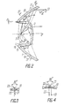
- the collimator of FIG. 2 differs from the collimator according to FIG. 1 by a simpler, smooth profile of the ring lens 4 and a more complicated structure of the reflector 2.
- the front part 15 of the lens 4 (in front of the optical axis FQ) has a plano-convex that rear part 16 of the same but a convex plane profile (with its convexity facing the focal point F), the flat profile sections being almost parallel to the axis 00 'of the collimator (and the press axis), namely with a slight deviation from the parallelism around a small pouring angle 8 of the order of 30 '- 60', which is the sign (required for direct extrusion) of the projections of the normals N 'and N "to the inside and outside surface of the lens 4 on the axis 00', in each case a negative one positive, guaranteed.
- Such a lens 4 covers the axial blind opening in the reflector 2 only by a small amount in the order of the thickness of the lens 4, which allows the dark spot in the light opening of the collimator to be almost completely ruled out without impairing the possibility of direct extrusion, by covering the blind opening of the reflector 2 with the aid of a disk-shaped converging lens 3 confocal with the collimator, the diameter of which is equal to the diameter of the front edge of the lens 4.
- the wide-angle ring lens 4 cannot be designed as completely confocal with the collimator; that is, its optical power is not sufficient to be able to execute the reflector 2 optically connected to it on a simple conical support layer with small axial dimensions. At the same time, these dimensions can be reduced relatively if the greatest refractive effect is concentrated in the front part 15 of the lens 4 due to the reduction in the optical force of its rear part 16.
- the aperture angle ⁇ 1 of the front part 15 of the lens 4 does not exceed 15-20 °, this part can be confocal with the collimator, while the optically connected front part l7 of the reflector 2 is conical.
- the aperture angle ⁇ 2 of the rear part 16 of the lens 4 is 30-60 0 , and its optical force is very small (given a thickness gradient that is the same as the part 15 in the section from the zero refraction point Q to the lens edge), while the rear part 18 of the reflector 2 is on Has a concave profile, which is connected to the part 17 at a point P, in which the axis FQ intersects the reflector 2, for example a parabolic profile with a focal point the location F of the imaginary image of the point F, which is generated by the rear part 16 of the lens 4.
- the reflector 2 of the collimator of FIG. 2 has radially oriented catadioptric prism elements 19 on the back of the supporting layer, the shape of which is shown in different cross sections in FIGS. 3, 4.
- Reflecting surfaces 20 of each prism 19 form a right total reflection surface angle in each cross section perpendicular to their cutting rib 21, the linear dimensions of which are proportional to the distance from the axis 00 '.
- the rib 21 is parallel to the front surface of the supporting layer, which front surface combines the functions of a refractive entry and exit surface of each prism 19.
- Such a reflector 2 is advantageously characterized by a lack of losses for Fresnel reflection, because the rays 22 reflected by the front surface of the reflector 2 coincide in the direction with the rays 23, which have been reflected by the faces 20 of each prism 19, whereby they thanks to the existing light filter, which serves as the lens 4, have a coloration common to them.
- the front surface of the collimator of Fig. 2 is smooth which enables it to operate without a protective glass.
- the reflector 2 does not need a mirror coating, thanks to the applied catadioptric reflection elements 7 (Fig. 1) and 19 (Fig. 2 - 4) in the form of prisms with total reflection
- the ring-shaped catadioptric elements 7 are more suitable for production in terms of press tool manufacture, but the radial prisms 19 (FIGS. 2-4) ensure a higher reflectivity and a smooth front side of the reflector 2.
- the collimator can be manufactured using the two-color casting process.
- the convex part of the collimator which consists of converging lenses 3, 4 and a catadioptric ring 8, which is not optically connected to the refractor 1 (FIG. 1), is made of a colored material and combines the functions of a light filter determining the color of the light signals.
- the concave part of the collimator, or more precisely the reflector 2 (with the exception of the ring 8), is made of a colorless material, whereby the light absorption in the body of the catadioptric reflector 2 is reduced while maintaining the signal color.
- the invention can be applied in lighting devices which are intended for mass production, for example in motor vehicle lights and headlights, traffic lights, headlights with low light output and in portable lanterns for various purposes.
Landscapes
- Physics & Mathematics (AREA)
- Engineering & Computer Science (AREA)
- General Engineering & Computer Science (AREA)
- General Physics & Mathematics (AREA)
- Optics & Photonics (AREA)
- Nitrogen And Oxygen Or Sulfur-Condensed Heterocyclic Ring Systems (AREA)
- Lenses (AREA)
- Non-Portable Lighting Devices Or Systems Thereof (AREA)
Abstract
Un collimateur automoulé de grande efficacité, de dimension axiale réduite et qui ne fait pas appel à des couches réflechissantes comporte les éléments suivants reliés de manière optique: un réfracteur convexe (1) et un réflecteur catadioptique concave (2) entourant le réflecteur (1), ces deux éléments étant réalisés sur une couche-support commune. Une partie latérale du réfacteur (1) comporte une lentille convergente annulaire (4), placée dans le trajet des rayons (13) depuis le point de focalisation (F) jusqu'au réflecteur (2), et comportant des disques Fresnel (5, 6) dont la position permet de réaliser le collimateur par moulage direct en une seule opération.
Applications Claiming Priority (1)
| Application Number | Priority Date | Filing Date | Title |
|---|---|---|---|
| PCT/SU1988/000030 WO1989007280A1 (fr) | 1988-02-05 | 1988-02-05 | Collimateur automoule |
Publications (2)
| Publication Number | Publication Date |
|---|---|
| EP0354961A1 true EP0354961A1 (fr) | 1990-02-21 |
| EP0354961A4 EP0354961A4 (en) | 1990-10-24 |
Family
ID=21617193
Family Applications (1)
| Application Number | Title | Priority Date | Filing Date |
|---|---|---|---|
| EP19880904289 Withdrawn EP0354961A4 (en) | 1988-02-05 | 1988-02-05 | Integrally-pressed collimator |
Country Status (4)
| Country | Link |
|---|---|
| EP (1) | EP0354961A4 (fr) |
| JP (1) | JPH02503131A (fr) |
| FI (1) | FI894700L (fr) |
| WO (1) | WO1989007280A1 (fr) |
Cited By (18)
| Publication number | Priority date | Publication date | Assignee | Title |
|---|---|---|---|---|
| WO1997049950A3 (fr) * | 1996-06-21 | 1998-02-05 | Imab Stiftung | Reflecteur en forme de cristal |
| WO2000001985A1 (fr) * | 1998-07-02 | 2000-01-13 | Jari Ruuttu | Appareil d'eclairage |
| EP1179705A1 (fr) * | 2000-08-07 | 2002-02-13 | CATEYE Co., Ltd. | Projecteur |
| EP1179706A1 (fr) * | 2000-08-07 | 2002-02-13 | CATEYE Co., Ltd. | Projecteur |
| EP1264207A4 (fr) * | 1999-07-22 | 2002-12-11 | Teledyne Lighting & Display | Distributeur et collimateur de lumiere |
| GB2391930A (en) * | 2002-07-04 | 2004-02-18 | Koito Mfg Co Ltd | Vehicle lamp with a translucent refraction and internal reflection region |
| EP1355108A3 (fr) * | 2002-04-18 | 2004-06-16 | VALEO Beleuchtung Deutschland GmbH | Dispositif d'éclairage pour vehicules automobiles |
| EP1596126A1 (fr) * | 2004-05-13 | 2005-11-16 | Valeo Vision | Dispositif d'éclairage ou de signalisation comportant une pièce optique qui réalise un faisceau réglementaire de manière autonome |
| WO2014136074A1 (fr) * | 2013-03-07 | 2014-09-12 | Koninklijke Philips N.V. | Agencement optique à profil bas |
| EP2861906A4 (fr) * | 2012-06-06 | 2015-10-07 | Coast Cutlery Co | Lentille à profil mince pour lampe de poche |
| EP2859269A4 (fr) * | 2012-06-06 | 2015-10-07 | Coast Cutlery Co | Optique de focalisation pour lampe de poche |
| US9416938B2 (en) | 2012-06-06 | 2016-08-16 | Coast Cutlery Co. | Integrated optic and bezel for flashlight |
| US9435515B2 (en) | 2014-01-31 | 2016-09-06 | Energizer Brands, Llc | Near-field lens with convex hyperbolic surface |
| CN106678739A (zh) * | 2017-02-15 | 2017-05-17 | 欧普照明股份有限公司 | 反射装置和光源模组 |
| CN107166187A (zh) * | 2017-06-08 | 2017-09-15 | 欧普照明股份有限公司 | 照明装置 |
| US20190360664A1 (en) * | 2017-02-15 | 2019-11-28 | Opple Lighting Co., Ltd. | Reflecting device, light source module and lighting device |
| CN112696644A (zh) * | 2020-07-23 | 2021-04-23 | 广州市意顿光学设计有限公司 | 一种变焦透镜 |
| US11927340B2 (en) * | 2016-10-26 | 2024-03-12 | Opple Lighting Co., Ltd. | Reflective device and light source module |
Families Citing this family (4)
| Publication number | Priority date | Publication date | Assignee | Title |
|---|---|---|---|---|
| JPH02504319A (ja) * | 1988-03-30 | 1990-12-06 | ナウチノ‐プロイズボドストベンノエ オビエディネニエ ポ アフトエレクトロニケ イ アフトトラクトルノム エレクトロオボルドバニユ | コリメータ |
| CN101750643B (zh) * | 2008-12-05 | 2012-12-19 | 鸿富锦精密工业(深圳)有限公司 | 透镜及采用该透镜的光源模组 |
| JP5596418B2 (ja) * | 2010-06-01 | 2014-09-24 | 株式会社小糸製作所 | 車両用灯具 |
| CN209371152U (zh) * | 2019-03-29 | 2019-09-10 | 欧普照明股份有限公司 | 光学元件及配光模组 |
Family Cites Families (8)
| Publication number | Priority date | Publication date | Assignee | Title |
|---|---|---|---|---|
| US2254962A (en) * | 1937-09-22 | 1941-09-02 | George M Cressaty | Unitary lens system |
| US2253409A (en) * | 1938-11-12 | 1941-08-19 | Westinghouse Electric & Mfg Co | Light projector |
| US2224178A (en) * | 1940-05-08 | 1940-12-10 | Ralph E Bitner | Catadioptrical lens system |
| GB1209377A (en) * | 1968-07-31 | 1970-10-21 | Ignacio Goytisolo Taltavull | Lighting fitting |
| US3883733A (en) * | 1974-03-18 | 1975-05-13 | Voevodsky John | Optical construction of a lens |
| GB2065858A (en) * | 1979-12-14 | 1981-07-01 | Rollei Werke Franke Heidecke | A reflector unit having variable angle light out-put |
| US4530040A (en) * | 1984-03-08 | 1985-07-16 | Rayovac Corporation | Optical focusing system |
| SU1282051A1 (ru) * | 1985-01-09 | 1987-01-07 | Латвийский Государственный Университет Им.П.Стучки | Коллиматор |
-
1988
- 1988-02-05 JP JP63503950A patent/JPH02503131A/ja active Pending
- 1988-02-05 EP EP19880904289 patent/EP0354961A4/ru not_active Withdrawn
- 1988-02-05 FI FI894700A patent/FI894700L/fi not_active IP Right Cessation
- 1988-02-05 WO PCT/SU1988/000030 patent/WO1989007280A1/fr not_active Ceased
Cited By (28)
| Publication number | Priority date | Publication date | Assignee | Title |
|---|---|---|---|---|
| WO1997049950A3 (fr) * | 1996-06-21 | 1998-02-05 | Imab Stiftung | Reflecteur en forme de cristal |
| WO2000001985A1 (fr) * | 1998-07-02 | 2000-01-13 | Jari Ruuttu | Appareil d'eclairage |
| US6474831B1 (en) | 1998-07-02 | 2002-11-05 | Jari Ruuttu | Light fitting |
| EP1264207A4 (fr) * | 1999-07-22 | 2002-12-11 | Teledyne Lighting & Display | Distributeur et collimateur de lumiere |
| EP1179705A1 (fr) * | 2000-08-07 | 2002-02-13 | CATEYE Co., Ltd. | Projecteur |
| EP1179706A1 (fr) * | 2000-08-07 | 2002-02-13 | CATEYE Co., Ltd. | Projecteur |
| US6527423B2 (en) | 2000-08-07 | 2003-03-04 | Cateye Co., Ltd. | Headlight |
| US6726346B2 (en) | 2000-08-07 | 2004-04-27 | Cateye Co., Ltd. | Headlight |
| US6986594B2 (en) | 2002-04-18 | 2006-01-17 | Valeo Wischersystem Gmbh | Lighting device for motor vehicles |
| EP1355108A3 (fr) * | 2002-04-18 | 2004-06-16 | VALEO Beleuchtung Deutschland GmbH | Dispositif d'éclairage pour vehicules automobiles |
| GB2391930A (en) * | 2002-07-04 | 2004-02-18 | Koito Mfg Co Ltd | Vehicle lamp with a translucent refraction and internal reflection region |
| GB2391930B (en) * | 2002-07-04 | 2005-06-08 | Koito Mfg Co Ltd | Vehicle lamp |
| US6951415B2 (en) | 2002-07-04 | 2005-10-04 | Koito Manufacturing Co., Ltd. | Vehicle lamp |
| EP1596126A1 (fr) * | 2004-05-13 | 2005-11-16 | Valeo Vision | Dispositif d'éclairage ou de signalisation comportant une pièce optique qui réalise un faisceau réglementaire de manière autonome |
| FR2870323A1 (fr) * | 2004-05-13 | 2005-11-18 | Valeo Vision Sa | Dispositif d'eclairage ou de signalisation comportant une piece optique qui realise un faisceau reglementaire de maniere autonome |
| DE112013000160B4 (de) | 2012-06-06 | 2020-01-02 | Coast Cutlery Co. | Dünnprofil-Linse für eine Taschenlampe |
| EP2861906A4 (fr) * | 2012-06-06 | 2015-10-07 | Coast Cutlery Co | Lentille à profil mince pour lampe de poche |
| EP2859269A4 (fr) * | 2012-06-06 | 2015-10-07 | Coast Cutlery Co | Optique de focalisation pour lampe de poche |
| US9416937B2 (en) | 2012-06-06 | 2016-08-16 | Coast Cutlery Co. | Thin profile lens for flashlight |
| US9416938B2 (en) | 2012-06-06 | 2016-08-16 | Coast Cutlery Co. | Integrated optic and bezel for flashlight |
| WO2014136074A1 (fr) * | 2013-03-07 | 2014-09-12 | Koninklijke Philips N.V. | Agencement optique à profil bas |
| US9435515B2 (en) | 2014-01-31 | 2016-09-06 | Energizer Brands, Llc | Near-field lens with convex hyperbolic surface |
| US11927340B2 (en) * | 2016-10-26 | 2024-03-12 | Opple Lighting Co., Ltd. | Reflective device and light source module |
| CN106678739A (zh) * | 2017-02-15 | 2017-05-17 | 欧普照明股份有限公司 | 反射装置和光源模组 |
| US20190360664A1 (en) * | 2017-02-15 | 2019-11-28 | Opple Lighting Co., Ltd. | Reflecting device, light source module and lighting device |
| US11131440B2 (en) * | 2017-02-15 | 2021-09-28 | Opple Lighting Co., Ltd. | Reflecting device, light source module and lighting device |
| CN107166187A (zh) * | 2017-06-08 | 2017-09-15 | 欧普照明股份有限公司 | 照明装置 |
| CN112696644A (zh) * | 2020-07-23 | 2021-04-23 | 广州市意顿光学设计有限公司 | 一种变焦透镜 |
Also Published As
| Publication number | Publication date |
|---|---|
| WO1989007280A1 (fr) | 1989-08-10 |
| FI894700A7 (fi) | 1989-10-04 |
| FI894700A0 (fi) | 1989-10-04 |
| EP0354961A4 (en) | 1990-10-24 |
| FI894700L (fi) | 1989-10-04 |
| JPH02503131A (ja) | 1990-09-27 |
Similar Documents
| Publication | Publication Date | Title |
|---|---|---|
| EP0354961A1 (fr) | Collimateur automoule | |
| DE69529866T2 (de) | Apparat zur gleichmässigen Beleuchtung eines Lichtventils | |
| DE69605265T2 (de) | Beleuchtungssystem mit integriertem Mikroteleskop in einer durchsichtigen Platte | |
| DE19910192C2 (de) | Reflektor mit einem konkaven rotationssymmetrischen Grundkörper und einer Facetten aufweisenden Reflexionsfläche | |
| AT398855B (de) | Mikroskopobjektiv zur einstellung auf unterschiedliche deckglasdicken | |
| EP0299091A1 (fr) | Dispositif de signalisation lumineuse | |
| DE19523148A1 (de) | Ultrakompakte komplexe optische Vorrichtung | |
| EP0762515A2 (fr) | Corps optique pour au moins une diode émettrice de lumière | |
| DE69608066T2 (de) | Optisches Gerät zum Abstandsmessen | |
| DE2941227A1 (de) | Lampe fuer kraftfahrzeuge | |
| EP0380663A1 (fr) | Collimateur | |
| DE3926618A1 (de) | Reflektorleuchte | |
| DE3786652T2 (de) | Transmissions-Overhead-Projektor mit reduzierter Höhe. | |
| DE3915119C1 (fr) | ||
| DE2842535A1 (de) | Abzweigelement | |
| DE19840475A1 (de) | Beleuchtungsapparatur | |
| AT16755U1 (de) | Leuchtenoptik | |
| DE3004422C2 (de) | Parabolreflektor | |
| EP0976971A2 (fr) | Dispositif pour l'émission de lumière, notamment lampe ou lanterne | |
| DE69018792T2 (de) | Fahrzeugscheinwerfer. | |
| DE3504366A1 (de) | Optisches system zur ausbildung eines kreisringfoermigen strahls | |
| DE3209113C2 (de) | Kraftfahrzeugscheinwerfer | |
| DE815181C (de) | Optisches System fuer Beleuchtungssysteme, z. B. Lichtsignale | |
| EP3211470B1 (fr) | Dispositif destiné à éclairer un réticule | |
| DE3207469C2 (de) | Anordnung zur Übertragung von mehreren Lichtkanälen zwischen zwei ralativ zueinander um eine gemeinsame Drehachse rotierenden Bauteilen |
Legal Events
| Date | Code | Title | Description |
|---|---|---|---|
| PUAI | Public reference made under article 153(3) epc to a published international application that has entered the european phase |
Free format text: ORIGINAL CODE: 0009012 |
|
| 17P | Request for examination filed |
Effective date: 19891005 |
|
| AK | Designated contracting states |
Kind code of ref document: A1 Designated state(s): DE FR GB IT NL SE |
|
| A4 | Supplementary search report drawn up and despatched | ||
| AK | Designated contracting states |
Kind code of ref document: A4 Designated state(s): DE FR GB IT NL SE |
|
| STAA | Information on the status of an ep patent application or granted ep patent |
Free format text: STATUS: THE APPLICATION IS DEEMED TO BE WITHDRAWN |
|
| 18D | Application deemed to be withdrawn |
Effective date: 19920901 |