EP1179706A1 - Projecteur - Google Patents
Projecteur Download PDFInfo
- Publication number
- EP1179706A1 EP1179706A1 EP01119070A EP01119070A EP1179706A1 EP 1179706 A1 EP1179706 A1 EP 1179706A1 EP 01119070 A EP01119070 A EP 01119070A EP 01119070 A EP01119070 A EP 01119070A EP 1179706 A1 EP1179706 A1 EP 1179706A1
- Authority
- EP
- European Patent Office
- Prior art keywords
- lens
- light
- light source
- headlight
- reflector
- Prior art date
- Legal status (The legal status is an assumption and is not a legal conclusion. Google has not performed a legal analysis and makes no representation as to the accuracy of the status listed.)
- Granted
Links
- 230000005540 biological transmission Effects 0.000 claims abstract description 10
- 238000009826 distribution Methods 0.000 abstract description 23
- 238000004519 manufacturing process Methods 0.000 abstract description 8
- 230000004907 flux Effects 0.000 description 13
- 238000001746 injection moulding Methods 0.000 description 3
- 230000007480 spreading Effects 0.000 description 3
- 238000003892 spreading Methods 0.000 description 3
- 239000007787 solid Substances 0.000 description 2
- 238000010586 diagram Methods 0.000 description 1
- 230000000694 effects Effects 0.000 description 1
- 230000009467 reduction Effects 0.000 description 1
Images


Classifications
-
- F—MECHANICAL ENGINEERING; LIGHTING; HEATING; WEAPONS; BLASTING
- F21—LIGHTING
- F21S—NON-PORTABLE LIGHTING DEVICES; SYSTEMS THEREOF; VEHICLE LIGHTING DEVICES SPECIALLY ADAPTED FOR VEHICLE EXTERIORS
- F21S43/00—Signalling devices specially adapted for vehicle exteriors, e.g. brake lamps, direction indicator lights or reversing lights
- F21S43/40—Signalling devices specially adapted for vehicle exteriors, e.g. brake lamps, direction indicator lights or reversing lights characterised by the combination of reflectors and refractors
-
- F—MECHANICAL ENGINEERING; LIGHTING; HEATING; WEAPONS; BLASTING
- F21—LIGHTING
- F21S—NON-PORTABLE LIGHTING DEVICES; SYSTEMS THEREOF; VEHICLE LIGHTING DEVICES SPECIALLY ADAPTED FOR VEHICLE EXTERIORS
- F21S41/00—Illuminating devices specially adapted for vehicle exteriors, e.g. headlamps
- F21S41/20—Illuminating devices specially adapted for vehicle exteriors, e.g. headlamps characterised by refractors, transparent cover plates, light guides or filters
- F21S41/28—Cover glass
-
- F—MECHANICAL ENGINEERING; LIGHTING; HEATING; WEAPONS; BLASTING
- F21—LIGHTING
- F21S—NON-PORTABLE LIGHTING DEVICES; SYSTEMS THEREOF; VEHICLE LIGHTING DEVICES SPECIALLY ADAPTED FOR VEHICLE EXTERIORS
- F21S43/00—Signalling devices specially adapted for vehicle exteriors, e.g. brake lamps, direction indicator lights or reversing lights
- F21S43/20—Signalling devices specially adapted for vehicle exteriors, e.g. brake lamps, direction indicator lights or reversing lights characterised by refractors, transparent cover plates, light guides or filters
- F21S43/26—Refractors, transparent cover plates, light guides or filters not provided in groups F21S43/235 - F21S43/255
Definitions
- the present invention relates to headlights, and more particularly to a headlight allowing simple adjustment of a delicate luminous intensity (or light) distribution pattern in manufacturing.
- the headlight is used for night traffic, so that attention should be paid not only to safety of a person utilizing the headlight but also to safety of a person driving a car coming from the opposite direction.
- the structure of a conventional headlight does not allow such adjustment down to detail.
- manual work has been done, e.g., to apply a light shield to a portion of the front lens.
- Such manual work would degrade efficiency in manufacturing, and a light distribution pattern exactly as desired would be hard to realize. Accordingly, there has been a demand for development of a headlight having a structure with which meticulous adjustment of a light distribution pattern can readily be performed in mass production.
- An object of the present invention is to provide a headlight that allows easy setting of a light distribution pattern down to detail when manufacturing.
- a headlight projecting light frontward includes: a light source; a reflector surrounding the light source from its backside to reflect light incident from the light source frontward; and a front lens located in front of the light source and the reflector.
- the front lens includes at least two portions different in light transmission characteristic from each other.
- Provision of the front lens having the portions different in light transmission characteristic makes it possible to determine, for each portion, a travelling direction of the luminous flux having been transmitted therethrough, and its spreading manner - diverged, parallel or converged - and the degree of such divergence or convergence.
- it becomes possible to design in advance the light distribution pattern down to detail e.g. by increasing the number of the portions having different light transmission characteristics, changing their positions or shapes, or increasing the aforementioned degree of divergence or the like.
- a mold for injection molding for example, can be prepared to conform to the design. Accordingly, it is possible to manufacture a headlight ensuring a desired light distribution pattern with an automated injection molding process, not relying on the manual work as in the conventional case.
- the front lens of the headlight of the present invention has a center lens in the center, and the center lens includes at least two portions having different light transmission characteristics.
- Luminous flux emitted from the light source directly reaches the center lens and is transmitted therethrough.
- the center lens is divided into the portions different in light transmission characteristic, the travelling direction and the spreading manner - diverged, parallel or converged - of the luminous flux having been transmitted through each portion can be determined independently from each other. This allows superimposition of the luminous flux transmitted through a portion of the front lens other than the center lens on the luminous flux transmitted through the center lens. As a result, it is possible to readily achieve a light distribution pattern controlled with extremely high precision.
- the at least two portions of the center lens include a portion from which the light incident from the light source is radiated with an increased degree of divergence, and a portion from which the light is radiated restricting the degree of divergence.
- Provision of such portions facilitates designing of a desired light distribution pattern. For example, a light distribution pattern for illuminating far ahead, that for illuminating beneath a user's foot in particular, and other patterns can be attained.
- the aforementioned portion from which the light is radiated restricting the degree of divergence radiates a parallel beam.
- the parallel beam can be formed, e.g. by disposing a convex lens at the relevant portion and positioning the light source at the focal point of the convex lens.
- the parallel beam thus radiated from the center of the front lens is allowed to be superimposed on the light beam transmitted through the remaining portion. As a result, it is possible to obtain various kinds of light distribution patterns that can illuminate far ahead.
- the center lens is composed of a concentric lens and a bar lens.
- the luminous flux passing through the center lens that having been transmitted through the concentric lens becomes a parallel beam, while that having been transmitted through the bar lens becomes a divergent beam that diverges outward.
- the parallel beam is obtained from the light transmitted through the concentric lens by positioning the light source at the focal point of the concentric lens.
- the aforementioned concentric lens is a Fresnel lens.
- Fresnel lens it is possible to reduce the thickness of the front lens in the relevant portion.
- the manufacturing process is also simplified as integral injection molding is allowed.
- the headlight of the present invention further includes a cylindrical condenser lens surrounding the light source from its periphery to transmit the light incident from the light source, and a reflector surrounding the light source and the cylindrical condenser lens from their backsides to reflect the light transmitted through the cylindrical condenser lens frontward.
- the cylindrical condenser lens transmits the light emitted from the light source sideward, restricting its degree of divergence.
- the light transmitted through the cylindrical condenser lens generally forms a parallel beam. If such a cylindrical condenser lens is not provided, in order to reflect luminous flux of the same quantity, a reflector would be required which has a size covering an area up to a crossing point with a "downsizing reference line" that is an extended line of the line connecting the light source and a position where the front end of the cylindrical convex lens is supposed to be located.
- the cylindrical condenser lens With provision of the cylindrical condenser lens, the light received from the light source can be condensed, so that a reflector only needs to cover an area up to the front end of the cylindrical condenser lens.
- This reduction in size of the reflector allows positioning of the front lens and the light source closer to each other. Therefore, using a center lens of the same diameter, the solid angle at the light source encompassing the center lens is increased. The luminous flux passing through the center lens is thus increased, so that the influence of the center lens on the light distribution pattern is increased correspondingly.
- the explanation about the solid angle not only applies to the center lens, but also applies to the entire front lens. Accordingly, by the downsizing described above, the at least two portions with different light transmission characteristics provided at the front lens come to have a great influence on the light distribution pattern.
- FIG. 1 is a perspective view of the headlight according to an embodiment of the present invention.
- This headlight 10 is attached to a bicycle and projects light frontward from a front lens 5 including a center lens 6.
- Fig. 2 is an exploded view of portions of the headlight shown in Fig. 1.
- Front lens 5 including center lens 6 and a connect portion 12 by which the front lens is attached to a housing (not shown) are formed in one piece.
- Center lens 6 is composed of a bar lens 6b and a concentric lens 6a.
- a multi-surface mirror 3 and a cylindrical convex lens 2 surrounded by the multi-surface mirror are provided.
- a Fresnel lens is employed as the cylindrical convex lens to achieve a sufficient effect of the convex lens with a thin lens.
- a light source 1 with a filament (not shown) is inserted into Fresnel lens 2. The light source is supplied with power via a socket 11.
- Fig. 3 is a cross sectional view showing light paths of the light emitted from the light source when the headlight is in operation.
- the filament has been designed to emit light from a narrow range on a line intersecting the central axis of the cylinder at right angles. This short filament is disposed approximately at the focal point of Fresnel lens 2.
- the parallel beam is reflected by multi-surface mirror 3 that is arranged to direct the light frontward with a predetermined angle, and projected frontward as a reflected light 20c. In Fig. 3, the light is projected frontward to slightly diverge.
- a cylindrical convex lens it is possible to promote downsizing of the headlight while ensuring the high efficiency, without a reflector covering a wide area.
- Fig. 4 shows light paths from the light source in the case where a common cone reflector 13 is used instead of the multi-surface mirror.
- the light 20a radiated from light source 1 sideward is transmitted through cylindrical Fresnel lens 2 and becomes parallel beam 20b, which is reflected by cone reflector 13 and projected frontward as parallel beam 20c.
- reflector 13 of the headlight according to the present invention provided with the cylindrical convex lens is compared in size with a reflector 113 of a conventional headlight unprovided with the cylindrical convex lens.
- the two headlights are designed to use the respective reflectors to reflect and project frontward the same quantities of luminous flux.
- reflector 113 is required to have a size that covers an area up to a crossing point with downsizing reference line 18 described above, which is an extended line of the line connecting light source 1 and a position where the front end of the cylindrical convex lens is supposed to be located.
- the cylindrical convex lens is used to project the parallel beam restricted in the degree of divergence, so that reflector 13 only needs to cover an area up to the front end of the convex lens. If the restricted degree of divergence is increased, a smaller reflector could be used according to the degree of restriction. With a reflector too small in size, however, it would become necessary to increase the dimensional accuracy of the reflector. Accordingly, the parallel beam is desired as the light restricted in divergence. The parallel beam facilitates designing of the surface of the reflector for forming an intended light distribution pattern.
- a reflector having a depth of approximately one third and a width of approximately four sevenths of the conventional reflector can be used to secure the same efficiency. This results in a remarkable downsizing since the volume of the rectangular parallelepiped for containing the reflector is reduced to approximately 10% of the conventional case.
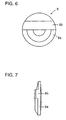
- Fig. 6 is a front view and Fig. 7 is a vertical sectional view of the center lens.
- Center lens 6 is composed of an upper bar-shaped convex lens 6b and a lower concentric Fresnel lens 6a.
- Fig. 8 is a front view of front lens 5 provided with center lens 6.
- Fig. 9 shows a cross section taken along the line IX-IX in Fig. 8.
- light source 1 is placed at the focal point of concentric Fresnel lens 6a.
- the light 16b transmitted through the upper bar lens of center lens 6 is projected frontward, diverged in an upper direction.
- the light 16a transmitted through the lower portion of center lens 6 is projected frontward as the parallel beam.
- Figs. 10 and 11 show cross sections taken along the lines X-X and XI-XI in Fig. 8, respectively. It is appreciated that light 16b transmitted through bar lens 6b is again projected frontward with divergence. It is also understood that light 16a transmitted through concentric lens 6a is again projected frontward as the parallel beam without divergence.
- Provision of the center lens having such portions different in light transmission characteristic increases the degree of freedom of feasible light distribution. For example, when riding on the bicycle, it is possible to illuminate frontward only in a narrow range into the distance to alleviate the dazzle suffered by a driver of an oncoming car on the opposite lane.
- the concentric lens and the bar lens may be replaced with each other in vertical relationship according to where on the bicycle the headlight is being attached or according to a light distribution pattern that is being desired.
Landscapes
- Engineering & Computer Science (AREA)
- General Engineering & Computer Science (AREA)
- Non-Portable Lighting Devices Or Systems Thereof (AREA)
Applications Claiming Priority (2)
| Application Number | Priority Date | Filing Date | Title |
|---|---|---|---|
| JP2000238210 | 2000-08-07 | ||
| JP2000238210A JP3390413B2 (ja) | 2000-08-07 | 2000-08-07 | ヘッドランプ |
Publications (2)
| Publication Number | Publication Date |
|---|---|
| EP1179706A1 true EP1179706A1 (fr) | 2002-02-13 |
| EP1179706B1 EP1179706B1 (fr) | 2003-05-14 |
Family
ID=18729948
Family Applications (1)
| Application Number | Title | Priority Date | Filing Date |
|---|---|---|---|
| EP01119070A Expired - Lifetime EP1179706B1 (fr) | 2000-08-07 | 2001-08-07 | Projecteur |
Country Status (7)
| Country | Link |
|---|---|
| US (2) | US6527423B2 (fr) |
| EP (1) | EP1179706B1 (fr) |
| JP (1) | JP3390413B2 (fr) |
| CN (1) | CN1135313C (fr) |
| DE (1) | DE60100269T2 (fr) |
| HK (1) | HK1044363B (fr) |
| TW (1) | TW533293B (fr) |
Cited By (4)
| Publication number | Priority date | Publication date | Assignee | Title |
|---|---|---|---|---|
| EP1355108A3 (fr) * | 2002-04-18 | 2004-06-16 | VALEO Beleuchtung Deutschland GmbH | Dispositif d'éclairage pour vehicules automobiles |
| FR2856774A1 (fr) * | 2003-06-24 | 2004-12-31 | Valeo Vision | Projecteur de vehicule automobile comportant des moyens pour etaler verticalement le faisceau lumineux |
| US8109662B2 (en) | 2005-08-22 | 2012-02-07 | Docter Optics Gmbh | Headlight lens for a vehicle headlight |
| EP2511601A3 (fr) * | 2011-04-12 | 2018-04-25 | Koito Manufacturing Co., Ltd. | Lampe de véhicule |
Families Citing this family (20)
| Publication number | Priority date | Publication date | Assignee | Title |
|---|---|---|---|---|
| JP3390413B2 (ja) * | 2000-08-07 | 2003-03-24 | 株式会社キャットアイ | ヘッドランプ |
| JP2004259541A (ja) | 2003-02-25 | 2004-09-16 | Cateye Co Ltd | 照明器具 |
| US20040264201A1 (en) * | 2003-06-30 | 2004-12-30 | Guide Corporation, A Delaware Corporation | Chromatic effect using light sources and condensing lenses |
| US20050002186A1 (en) * | 2003-07-01 | 2005-01-06 | Vector Products, Inc. | Multi-beam flashlight |
| WO2005005880A2 (fr) * | 2003-07-01 | 2005-01-20 | Vector Products, Inc. | Lampe de poche multifonctions et dispositif de commande |
| JP4061347B2 (ja) | 2003-08-05 | 2008-03-19 | 株式会社キャットアイ | 照明装置 |
| US8712858B2 (en) * | 2004-08-21 | 2014-04-29 | Directworks, Inc. | Supplier capability methods, systems, and apparatuses for extended commerce |
| FR2874994B1 (fr) * | 2004-09-07 | 2006-11-24 | Valeo Vision Sa | Projecteur d'eclairage ou de signalisation en forme de bandeau comportant un miroir plan a echelons |
| TWM275418U (en) * | 2004-12-03 | 2005-09-11 | Chip Hope Co Ltd | Lens with light uniformization |
| CN100462618C (zh) * | 2005-10-27 | 2009-02-18 | 财团法人车辆研究测试中心 | Led头灯及其灯罩 |
| FR2898402B1 (fr) * | 2006-03-07 | 2015-01-23 | Valeo Vision | Module optique pour projecteur automobile muni d'un element de deviation optique |
| US20090207624A1 (en) * | 2008-02-15 | 2009-08-20 | Acumen, Inc. | Headlight assembly permitting compensation for visibility changes |
| US20090240628A1 (en) * | 2008-03-20 | 2009-09-24 | Co-Exprise, Inc. | Method and System for Facilitating a Negotiation |
| US7931394B2 (en) * | 2008-03-31 | 2011-04-26 | Honda Motor Co., Ltd. | Front accessory light cover assembly |
| JP2010073409A (ja) * | 2008-09-17 | 2010-04-02 | Stanley Electric Co Ltd | 車両用灯具 |
| TWD137509S1 (zh) * | 2009-09-04 | 2010-10-21 | 酷普仕有限公司 | 自行車警示燈(一) |
| TWD137510S1 (zh) * | 2009-09-04 | 2010-10-21 | 酷普仕有限公司 | 自行車警示燈(二) |
| KR101672031B1 (ko) * | 2014-06-02 | 2016-11-02 | 현대모비스 주식회사 | 차량용 램프 모듈 |
| US11040748B1 (en) * | 2020-08-19 | 2021-06-22 | Dirk Steyn | Bicycle headlight with linear LED devices and related methods |
| FR3123411B1 (fr) | 2021-05-31 | 2023-08-04 | Valeo Vision | Module lumineux de véhicule automobile. |
Citations (4)
| Publication number | Priority date | Publication date | Assignee | Title |
|---|---|---|---|---|
| US1955599A (en) * | 1931-07-30 | 1934-04-17 | Us Holding Corp | Motor vehicle headlight |
| GB611032A (en) * | 1945-01-25 | 1948-10-25 | Raleigh Cycle Company Ltd | Improvements in directional beam electric lamps |
| GB820500A (en) * | 1956-05-22 | 1959-09-23 | Ever Ready Co | Improvements in or relating to lamps |
| EP0354961A1 (fr) * | 1988-02-05 | 1990-02-21 | Nauchno-Proizvodstvennoe Obiedinenie Po Avtoelektronike I Avtotraktornomu Elektrooborudovaniju | Collimateur automoule |
Family Cites Families (9)
| Publication number | Priority date | Publication date | Assignee | Title |
|---|---|---|---|---|
| FR2378234A1 (fr) * | 1977-01-24 | 1978-08-18 | Cibie Projecteurs | Feu de signalisation a catadioptre incorpore pour vehicule |
| SE439342C (sv) | 1981-09-28 | 1996-11-18 | Bo Reiner Andersson | Ventilanordning för styrning av en linjär eller roterande hydraulmotor |
| JPH0424203A (ja) | 1990-05-21 | 1992-01-28 | Brother Ind Ltd | テープ状素材の加熱接着装置 |
| DE4315393C2 (de) * | 1993-05-08 | 2002-10-31 | Bosch Gmbh Robert | Kraftfahrzeugscheinwerfer mit einem Reflektor und einer Streulinse |
| JPH08268154A (ja) | 1995-03-28 | 1996-10-15 | Toyota Motor Corp | 車両用灯具 |
| JP3165038B2 (ja) | 1996-07-25 | 2001-05-14 | 株式会社小糸製作所 | 車輌用前照灯 |
| JP4062643B2 (ja) | 1998-05-13 | 2008-03-19 | スタンレー電気株式会社 | 灯具 |
| DE19856281B4 (de) | 1998-12-07 | 2013-06-13 | Automotive Lighting Reutlingen Gmbh | Scheinwerfer für Fahrzeuge nach dem Projektionsprinzip |
| JP3390413B2 (ja) * | 2000-08-07 | 2003-03-24 | 株式会社キャットアイ | ヘッドランプ |
-
2000
- 2000-08-07 JP JP2000238210A patent/JP3390413B2/ja not_active Expired - Fee Related
-
2001
- 2001-07-20 US US09/909,697 patent/US6527423B2/en not_active Expired - Fee Related
- 2001-07-23 TW TW090117871A patent/TW533293B/zh not_active IP Right Cessation
- 2001-08-07 EP EP01119070A patent/EP1179706B1/fr not_active Expired - Lifetime
- 2001-08-07 DE DE60100269T patent/DE60100269T2/de not_active Expired - Fee Related
- 2001-08-07 CN CNB011407336A patent/CN1135313C/zh not_active Expired - Fee Related
-
2002
- 2002-08-14 HK HK02105962.1A patent/HK1044363B/zh not_active IP Right Cessation
-
2003
- 2003-03-03 US US10/378,298 patent/US20030128547A1/en not_active Abandoned
Patent Citations (4)
| Publication number | Priority date | Publication date | Assignee | Title |
|---|---|---|---|---|
| US1955599A (en) * | 1931-07-30 | 1934-04-17 | Us Holding Corp | Motor vehicle headlight |
| GB611032A (en) * | 1945-01-25 | 1948-10-25 | Raleigh Cycle Company Ltd | Improvements in directional beam electric lamps |
| GB820500A (en) * | 1956-05-22 | 1959-09-23 | Ever Ready Co | Improvements in or relating to lamps |
| EP0354961A1 (fr) * | 1988-02-05 | 1990-02-21 | Nauchno-Proizvodstvennoe Obiedinenie Po Avtoelektronike I Avtotraktornomu Elektrooborudovaniju | Collimateur automoule |
Cited By (5)
| Publication number | Priority date | Publication date | Assignee | Title |
|---|---|---|---|---|
| EP1355108A3 (fr) * | 2002-04-18 | 2004-06-16 | VALEO Beleuchtung Deutschland GmbH | Dispositif d'éclairage pour vehicules automobiles |
| US6986594B2 (en) | 2002-04-18 | 2006-01-17 | Valeo Wischersystem Gmbh | Lighting device for motor vehicles |
| FR2856774A1 (fr) * | 2003-06-24 | 2004-12-31 | Valeo Vision | Projecteur de vehicule automobile comportant des moyens pour etaler verticalement le faisceau lumineux |
| US8109662B2 (en) | 2005-08-22 | 2012-02-07 | Docter Optics Gmbh | Headlight lens for a vehicle headlight |
| EP2511601A3 (fr) * | 2011-04-12 | 2018-04-25 | Koito Manufacturing Co., Ltd. | Lampe de véhicule |
Also Published As
| Publication number | Publication date |
|---|---|
| TW533293B (en) | 2003-05-21 |
| CN1337543A (zh) | 2002-02-27 |
| HK1044363A1 (en) | 2002-10-18 |
| JP3390413B2 (ja) | 2003-03-24 |
| HK1044363B (zh) | 2004-12-03 |
| DE60100269T2 (de) | 2003-12-18 |
| CN1135313C (zh) | 2004-01-21 |
| EP1179706B1 (fr) | 2003-05-14 |
| US20030128547A1 (en) | 2003-07-10 |
| JP2002050213A (ja) | 2002-02-15 |
| DE60100269D1 (de) | 2003-06-18 |
| US20020018347A1 (en) | 2002-02-14 |
| US6527423B2 (en) | 2003-03-04 |
Similar Documents
| Publication | Publication Date | Title |
|---|---|---|
| EP1179706B1 (fr) | Projecteur | |
| EP1179705B1 (fr) | Projecteur | |
| US8348486B2 (en) | Vehicular lamp unit and vehicular lamp | |
| EP1357333B1 (fr) | Unité source de lumière pour lampe de véhicule | |
| EP2767750B1 (fr) | Phare de véhicule | |
| US7168836B2 (en) | Vehicle illumination lamp | |
| JP5869223B2 (ja) | 車両用前照灯 | |
| EP1357332B1 (fr) | Unité source de lumière pour lampe de véhicule | |
| KR100570481B1 (ko) | 차량용 전조등 | |
| EP2182272B1 (fr) | Unité de phare de véhicule et phare de véhicule | |
| EP2366940B1 (fr) | Phare de projecteur de motocyclette | |
| JP2003065805A (ja) | 照明及び表示装置 | |
| JP2004158292A (ja) | 車両用前照灯 | |
| US20070177400A1 (en) | Vehicle lighting device | |
| EP0573995B1 (fr) | Dispositif d'éclairage du type à projection | |
| US7341367B2 (en) | Vehicle headlamp | |
| EP4050251B1 (fr) | Dispositif de phare pour véhicule | |
| JP4403586B2 (ja) | 車両用灯具 | |
| JP2002175709A (ja) | 車両用灯具 | |
| JPH0251201B2 (fr) | ||
| JPH0337246B2 (fr) | ||
| CZ338099A3 (cs) | Vozidlové svítidlo | |
| JPS6077302A (ja) | 自動車用前照灯 | |
| JPH09293401A (ja) | 車両用の霧灯 |
Legal Events
| Date | Code | Title | Description |
|---|---|---|---|
| PUAI | Public reference made under article 153(3) epc to a published international application that has entered the european phase |
Free format text: ORIGINAL CODE: 0009012 |
|
| 17P | Request for examination filed |
Effective date: 20011129 |
|
| AK | Designated contracting states |
Kind code of ref document: A1 Designated state(s): DE FR GB Kind code of ref document: A1 Designated state(s): AT BE CH CY DE DK ES FI FR GB GR IE IT LI LU MC NL PT SE TR |
|
| AX | Request for extension of the european patent |
Free format text: AL;LT;LV;MK;RO;SI |
|
| GRAH | Despatch of communication of intention to grant a patent |
Free format text: ORIGINAL CODE: EPIDOS IGRA |
|
| 17Q | First examination report despatched |
Effective date: 20020402 |
|
| AKX | Designation fees paid |
Free format text: DE FR GB |
|
| GRAH | Despatch of communication of intention to grant a patent |
Free format text: ORIGINAL CODE: EPIDOS IGRA |
|
| GRAA | (expected) grant |
Free format text: ORIGINAL CODE: 0009210 |
|
| AK | Designated contracting states |
Designated state(s): DE FR GB |
|
| REG | Reference to a national code |
Ref country code: GB Ref legal event code: FG4D |
|
| REG | Reference to a national code |
Ref country code: IE Ref legal event code: FG4D |
|
| REF | Corresponds to: |
Ref document number: 60100269 Country of ref document: DE Date of ref document: 20030618 Kind code of ref document: P |
|
| ET | Fr: translation filed | ||
| PLBE | No opposition filed within time limit |
Free format text: ORIGINAL CODE: 0009261 |
|
| STAA | Information on the status of an ep patent application or granted ep patent |
Free format text: STATUS: NO OPPOSITION FILED WITHIN TIME LIMIT |
|
| 26N | No opposition filed |
Effective date: 20040217 |
|
| REG | Reference to a national code |
Ref country code: IE Ref legal event code: MM4A |
|
| PGFP | Annual fee paid to national office [announced via postgrant information from national office to epo] |
Ref country code: GB Payment date: 20060802 Year of fee payment: 6 |
|
| PGFP | Annual fee paid to national office [announced via postgrant information from national office to epo] |
Ref country code: DE Payment date: 20060803 Year of fee payment: 6 |
|
| PGFP | Annual fee paid to national office [announced via postgrant information from national office to epo] |
Ref country code: FR Payment date: 20060808 Year of fee payment: 6 |
|
| GBPC | Gb: european patent ceased through non-payment of renewal fee |
Effective date: 20070807 |
|
| REG | Reference to a national code |
Ref country code: FR Ref legal event code: ST Effective date: 20080430 |
|
| PG25 | Lapsed in a contracting state [announced via postgrant information from national office to epo] |
Ref country code: DE Free format text: LAPSE BECAUSE OF NON-PAYMENT OF DUE FEES Effective date: 20080301 |
|
| PG25 | Lapsed in a contracting state [announced via postgrant information from national office to epo] |
Ref country code: FR Free format text: LAPSE BECAUSE OF NON-PAYMENT OF DUE FEES Effective date: 20070831 |
|
| PG25 | Lapsed in a contracting state [announced via postgrant information from national office to epo] |
Ref country code: GB Free format text: LAPSE BECAUSE OF NON-PAYMENT OF DUE FEES Effective date: 20070807 |