EP0355069A2 - Verzweigungssystem mit variabler Verzögerung - Google Patents
Verzweigungssystem mit variabler Verzögerung Download PDFInfo
- Publication number
- EP0355069A2 EP0355069A2 EP89402133A EP89402133A EP0355069A2 EP 0355069 A2 EP0355069 A2 EP 0355069A2 EP 89402133 A EP89402133 A EP 89402133A EP 89402133 A EP89402133 A EP 89402133A EP 0355069 A2 EP0355069 A2 EP 0355069A2
- Authority
- EP
- European Patent Office
- Prior art keywords
- branch
- instructions
- instruction
- sequence
- command
- Prior art date
- Legal status (The legal status is an assumption and is not a legal conclusion. Google has not performed a legal analysis and makes no representation as to the accuracy of the status listed.)
- Withdrawn
Links
Images


Classifications
-
- G—PHYSICS
- G06—COMPUTING OR CALCULATING; COUNTING
- G06F—ELECTRIC DIGITAL DATA PROCESSING
- G06F9/00—Arrangements for program control, e.g. control units
- G06F9/06—Arrangements for program control, e.g. control units using stored programs, i.e. using an internal store of processing equipment to receive or retain programs
- G06F9/30—Arrangements for executing machine instructions, e.g. instruction decode
- G06F9/38—Concurrent instruction execution, e.g. pipeline or look ahead
- G06F9/3802—Instruction prefetching
- G06F9/3804—Instruction prefetching for branches, e.g. hedging, branch folding
-
- G—PHYSICS
- G06—COMPUTING OR CALCULATING; COUNTING
- G06F—ELECTRIC DIGITAL DATA PROCESSING
- G06F9/00—Arrangements for program control, e.g. control units
- G06F9/06—Arrangements for program control, e.g. control units using stored programs, i.e. using an internal store of processing equipment to receive or retain programs
- G06F9/30—Arrangements for executing machine instructions, e.g. instruction decode
- G06F9/38—Concurrent instruction execution, e.g. pipeline or look ahead
- G06F9/3836—Instruction issuing, e.g. dynamic instruction scheduling or out of order instruction execution
- G06F9/3842—Speculative instruction execution
Definitions
- Pipeline computers bear the name by reason of some similarity to petroleum pipelines that pass different products in sequence through interconnected sections. Before one petroleum product clears a pipeline, several others may have been introduced. By analogy, in pipeline computers, a series of stages perform distinct steps on sequences of passing data.
- an initial stage fetches instructions, a second stage decodes the instructions, a third stage locates operands and so on.
- the final stage in the pipeline may update a program counter to provide the address of the next instruction in a current sequence.
- the first stage of a pipeline computer operates with a program counter value that is several cycles ahead of the counter value produced by the last stage.
- the future value of the program counter is estimated for the initial stage on the basis of successive increments.
- a branch operation commanded by a branch instruction breaks the pipeline normally requiring the program counter to split from an existing sequence.
- interaction between the first and last stages of a pipeline computer is effected when a branch command alters the program counter nonsequentially. That is to say, during as many cycles as there are stages in the pipeline, no instructions can be issued. The process is thus blocked with a resulting loss of time.
- branch operations may involve further complications and loss of time in view of conditions that remain undetermined when a conditional branch instruction reaches the last stage of the pipeline.
- the delayed branch affords a way to prevent the usual loss of time attendant pipeline breaks and to enable use of what is already in the pipeline. It significantly improves the performance of branch instructions, the occurrence of which are very common (typically more than fourteen percent). Time losses, traditionally attendant pipeline breaks, are avoided by accommodating effective programming of the system.
- the present invention involves a system (apparatus and process) involving variable delay branch operation which accommodates programming of both conditional and unconditional branch operations as for use in a pipeline computer to avoid the loss of time.
- the system implements steps to accommodate a branch command, followed by a split command to indicate the time for the jump.
- the split command comprises a bit in an instruction to command the execution of a branch. That is, a jump is not executed immediately after a branch command but rather is delayed by a variable number of program instructions pending a split command in the form of a split bit.
- the variable number is under the control of the programmer, enabling considerable flexibility and time saving.
- the delay must be at least one cycle.
- the branch command does not indicate the imposed delay, but rather the system affords flexibility. If no delay is desired, the branch command can be followed by a no-operation instruction containing a split bit.
- the system affords a variable delay during which branch or target instructions are fetched enabling a prompt jump as on the occurrence of a split bit.
- the system of the present invention enables a substantial saving of time and flexibility in the operation of a pipeline computer.
- the saving of time results because with a branch, the currently operating units continue to function while the target instructions are fetched and loaded.
- condition codes are developed concurrently with useful operation.
- the effectiveness of the system is somewhat dependent on the extent of its utilization by an instant operating program.
- FIGURE 1 the system is illustrated with specific regard to the processing of programmed instructions. It is to be recognized that the system might be variously illustrated with a variety of functional components; however, for simplicity and ease of understanding, the disclosed arrangement is detailed primarily with regard to the structural elements related to the branch operations of the present development. Accommodating practical considerations, the disclosed embodiment is presented as a manageable teaching disclosure for one skilled in the art. Accordingly, a control system 10 (FIGURE 1, upper right) represents any of various computer structures or arrangements as well known in the art including multiple processors or function units, memory and programmed control apparatus along with input/output facility. As well known, forms of such apparatus execute programmed instructions in a linked sequence and thereby accomplish a desired operation.
- the system 10 drives an instruction pipeline 12 (FIGURE 1, top central) through which instructions are supplied selectively to one of a pair of instruction buffers 14 and 16. That is, from the pipeline 12, instructions may be supplied either to the instruction buffer 14 or the instruction buffer 16.
- the buffers 14 and 16 comprise FIFO's (first-in-first-out registers) in which instructions are stacked for delivery in sequence to execution units 18.
- FIFO's first-in-first-out registers
- an instruction is continually available for the execution units 18.
- the execution units 18 may involve a variety of complex and extensive structure. However, various forms of such structures are well known and have been widely used in the past.
- the units 18 also include five detectors to provide five specific signals to the control system 10 in relation to branch operations. Specifically, from within the instruction execution units 18, a detector 19 senses branch commands to provide a branch signal in a line 20; a detector 21 senses a conditional branch to provide a representative signal in a line 22; a detector 23 senses the fulfillment of a condition to provide a condition-met signal in a line 24; a detector 25 senses a split bit to provide a split signal in a line 26 and a detector 27 senses that condition codes are ready to provide a code-ready signal in a line 28.
- These control signals are instrumental in branch operations of the system to effect delayed jumps from one sequence of program instructions to another with reduced loss of computing time.
- the selection of instructions in sequence for the buffers 14 and 16 involves a pair of program counters 29 and 30 (lower right) along with a pair of instruction address registers 31 and 32 (upper right).
- the program counters 29 and 30 are incremented to specify sequences of instruction addresses for the registers 31 and 32 serving the instruction pipeline 12.
- current operation involves supplying instructions in accordance with the operation of: one of the instruction buffers 14 or 16, one of the program counters 29 or 30 and one of the address registers 31 or 32.
- one of each of the pairs is designed "current” and the other is designed “target”.
- the currently operating units continue to function, accordingly to save time while the target units are activated to accummulate a set of target instructions in the target instruction buffer. That is, on a branch command, there are still instructions to execute while the target or alternate buffer is being filled, specifically, instructions presently in the buffer and the pipeline. In accordance herewith, those instructions are executed as preparations proceed for a jump without a break in operating cycles. Thus, when a jump occurs, the target units are prepared and become the current units.
- the buffer 14, the counter 29 and the register 31 are designated “current” and the buffer 16, the counter 30 and the register 32 are designated “target”.
- target functions switch to current functions. That is, with each jump, the current operation shifts between: the instruction buffers 14 and 16; the program counters 29 and 30; and the address registers 31 and 32.
- the system accommodates jump operations that avoid breaks in the pipeline with attendant losses of time.
- the operating sequences and control functions attendant the shifts are treated in greater detail below. At this point, the branch command operations will be considered.
- branch commands may be either conditional or unconditional. In either case, after a variable interval, a branch command is followed by an instruction containing a split command indicating a time for execution. Following the appearance of an unconditional branch command in the execution units 18, the occurrence of an instruction word containing a split command prompts an immediate jump to the target program sequence.
- conditional branch command In the case of a conditional branch command, the operation is somewhat more complex. If the condition imposed by a conditional branch has been met upon the occurrence of a split bit, the system jumps to the target program. Such operation is economical of time; however, a split bit also may occur before the condition codes are ready. In that case, the system waits until the condition codes are ready and a determination can be made whether or not the condition is met. If so, the system jumps. Alternatively, if a condition is not met, operation continues in the current program sequence. Accordingly, the current target buffer is flushed and is ready to be used on the occurrence of a subsequent branch instruction.
- target instructions are accumulated for immediate use at the time of a jump.
- FIGURE 1 assume a sequence of current instructions is being processed through the buffer 14 when a branch command occurs. With the occurrence of such a command, target instructions are provided from the pipeline 12 to the instruction buffer 16. However, the current operation continues (executing current instructions) until a split bit occurs. Assuming a jump occurs, the system immediately shifts to the target instruction sequence and the instruction buffer 16 becomes the source of current instructions.
- the program counters 29 and 30 along with the address registers 31 and 32 operate in similar alternative patterns.
- the ninth bit of the instruction (FIGURE 2) is consistently employed as the split bit 35.
- a binary "0" indicates no split and a binary "1" commands a split or jump operation.
- bits ten through fifteen (field 37) and sixteen through twenty-one (field 39) generally designate registers as for destinations, operands and so on.
- Various formats for such fields are well known.
- the word may include additional fields as suggested by the broken line 41 in FIGURE 2.
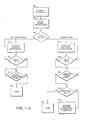
- FIGURE 2 Assume that such a cyclic routine is interrupted by the execution of an instruction word (FIGURE 2) with an unconditional branch command in the field 33. The event is symbolized in the flow diagram of FIGURE 3 by a block 34. Reference will now be made somewhat concurrently to FIGURES 1 and 3.
- the control system 10 sets the target program counter 30 in accordance with the branch to specify the target instruction address for placement in the target address register 32.
- the pipeline 12 then develops the target instruction in the target instruction buffer 16. The cycle is repeated and several instructions of the target sequence are set in the target instruction buffer 16. The operation of fetching target instructions is symbolized in FIGURE 3 by a block 36.
- each execution is tested for a split bit, i.e. the presence of a "1" in the bit location 35 (FIGURE 2).
- the split bit tests are represented for unconditional and conditional branches in FIGURE 3 by the test blocks 42 and 48 respectively.
- split command split bit "1"
- current instructions are processed in sequence until an instruction appears with a split command. It is the resulting delay that enables setting up the target instruction sequence for immediate operation on command.
- a split bit "1" prompts a jump when the target instructions are ready as indicated by the block 44 (FIGURE 3).
- the current sequential stream of instructions is switched from the buffer 14 (FIGURE 1) to the buffer 16. Accordingly, the buffer 16 then carries current instructions and the buffer 14 stands ready to receive target instructions. In the next jump, the sequence of current instructions will shift from the buffer 16 back to the buffer 14. Similar shifts occur between the program counters 29 and 30 along with the address registers 31 and 32.
- a split bit is presented after a delay that sees the development of condition codes, resolution of the condition and useful processing.
- Such operating pattern is economical of time as it accommodates continuity in pipeline operation.
- the sytem is not confined to such patterns of operation.
- a split bit (“1") may occur before the condition codes are ready for a determination of whether the condition has been met.
- a jump is not initiated until a split bit has occurred (box 40, FIGURE 3) and the condition codes are ready (box 50, FIGURE 3).
- a test is made to determine if the condition has been met (box 52). On that determination, the system either jumps (box 53) or current operation is resumed without a pending branch (box 55).
- the units 18 execute current instructions.
- the executions include: testing for a split bit "1", testing for the readiness of condition codes and testing as to whether the condition is met.
- the results of these tests are manifest by the signals in paths 24, 26 and 28. Specifically, if the condition codes are ready, a codes-ready signal appears in the path 28. If the condition is met, a signal is provided from the detector 23 through the condition-met path 26 to the system 10. A split bit prompts a signal in path 26.
- condition has not been met when a split bit "1" occurs, the system continues with the current sequence, or is blocked until the condition codes are available and the condition can be tested.
- a jump occurs from a conditional branch command, it involves shifts to the target operating units precisely as described above with reference to FIGURE 1 in the case of an unconditional branch. If a conditional branch does not result in a jump (condition not met), the target units (instruction buffer 16, program counter 27, and address register 31) are cleared to await the occurrence of another branch command.
- the system of FIGURE 1 has been described to involve three switched pairs of units that alternate functions executing current branch operations.
- the structures are: the buffers 14 and 16; the program counters 29 and 30 and the address registers 31 and 32.
- the controls and signal paths involving the three structures are somewhat distinct and will now be considered in greater detail with reference to FIGURE 4. Note that previously identified components of the system of FIGURE 4 bear the same reference numerals as previously assigned. Also, in the system of FIGURE 4, a single block 66 (upper left) represents the considerable computer facility including function units, master control, execution apparatus, memory and so on.
- the block 66 can be variously fragmented and explained; however, with respect to the structure of the present invention, the system simply performs control functions which may be readily performed by any of a variety of computer systems as well known and widely used in the prior art.
- the program counter 29 (lower left) is active with its contents incremented cyclically by a unit 74 as supplied through a multiplexer 76 to the block 66.
- the multiplexer 76 may supply values from the program counter 30.
- the counters 29 and 30 are controlled by a counter control 75 which is in turn controlled by the unit 66. Distinct from the control 75, the control unit 72 (central) controls a multiplexer 81 (lower right) for passing addresses from either the register 31 or the register 32 to the pipeline 12. Signal-represented addresses are set in the registers 31 and 32 by an address source 83 (lower right) which is coupled to the control 66.
- an executed instruction contains a branch command. Responsive to such command, the control 66 actuates the program counter control 75 to set the branch target number in the counter 30. Concurrently, the control 66 actuates the unit 72 switching the multiplexer 81 to cycle the number from the counter 30 through the increment unit 74 to the control 66.
- the address source 83 (lower right) develops the target address setting it in the buffer register 30 from which it passes through the multiplexer 81 to the pipeline 12.
- a target instruction is supplied from the pipeline 12 through the fetch control 68 to the instruction buffer 16.
- the cycle is repeated advancing the program counter 30 with the result that a sequence of target instructions are developed in the buffer 16.
- the instruction buffer 14 and the multiplexer 70 continue to provide instructions to the control 66 for execution.
- the split bit specifies the time of a jump.
- the split bit "1" commands a jump only if the imposed conditions are met as determined within the control 66 (instruction execution units 18, FIGURE 1). Otherwise, the branch is canceled with operating units cleared.
Landscapes
- Engineering & Computer Science (AREA)
- Software Systems (AREA)
- Theoretical Computer Science (AREA)
- Physics & Mathematics (AREA)
- General Engineering & Computer Science (AREA)
- General Physics & Mathematics (AREA)
- Advance Control (AREA)
- Executing Machine-Instructions (AREA)
Applications Claiming Priority (2)
| Application Number | Priority Date | Filing Date | Title |
|---|---|---|---|
| US07/231,928 US4974155A (en) | 1988-08-15 | 1988-08-15 | Variable delay branch system |
| US231928 | 1988-08-15 |
Publications (2)
| Publication Number | Publication Date |
|---|---|
| EP0355069A2 true EP0355069A2 (de) | 1990-02-21 |
| EP0355069A3 EP0355069A3 (de) | 1992-07-08 |
Family
ID=22871194
Family Applications (1)
| Application Number | Title | Priority Date | Filing Date |
|---|---|---|---|
| EP19890402133 Withdrawn EP0355069A3 (de) | 1988-08-15 | 1989-07-27 | Verzweigungssystem mit variabler Verzögerung |
Country Status (3)
| Country | Link |
|---|---|
| US (1) | US4974155A (de) |
| EP (1) | EP0355069A3 (de) |
| JP (1) | JPH02161524A (de) |
Cited By (12)
| Publication number | Priority date | Publication date | Assignee | Title |
|---|---|---|---|---|
| EP0655679A3 (de) * | 1993-11-26 | 1995-06-28 | Fujitsu Ltd | |
| EP0689131A1 (de) | 1994-06-22 | 1995-12-27 | STMicroelectronics Limited | Rechnersystem zur Ausführung von Verzweigungsbefehlen |
| EP0893756A3 (de) * | 1997-07-25 | 2000-11-15 | Motorola, Inc. | Verfahren und Vorrichtung zur Steuerung der Ausführung bedingter Verzweigungen in einem Datenprozessor |
| WO2000070447A3 (en) * | 1999-05-13 | 2001-05-25 | Arc Internat U S Holdings Inc | Method and apparatus for jump delay slot control in a pipelined processor |
| EP1071010A3 (de) * | 1999-07-23 | 2001-11-14 | International Business Machines Corporation | Entkoppeltes Abrufen und Ausführen von Befehlen mit statischer Verzweigungsvorhersage |
| FR2920557A1 (fr) * | 2007-12-21 | 2009-03-06 | Thomson Licensing Sas | Dispositif et methode de sequencement de taches |
| US8386972B2 (en) | 1998-10-14 | 2013-02-26 | Synopsys, Inc. | Method and apparatus for managing the configuration and functionality of a semiconductor design |
| US8688879B2 (en) | 2000-03-10 | 2014-04-01 | Synopsys, Inc. | Memory interface and method of interfacing between functional entities |
| US9003166B2 (en) | 2006-12-01 | 2015-04-07 | Synopsys, Inc. | Generating hardware accelerators and processor offloads |
| WO2015113879A1 (en) * | 2014-01-29 | 2015-08-06 | Telefonaktiebolaget L M Ericsson (Publ) | Efficient use of branch delay slots and branch prediction in pipelined computer architectures |
| US9430245B2 (en) | 2014-03-28 | 2016-08-30 | Telefonaktiebolaget Lm Ericsson (Publ) | Efficient branch predictor history recovery in pipelined computer architectures employing branch prediction and branch delay slots of variable size |
| WO2017220974A1 (en) * | 2016-06-22 | 2017-12-28 | Arm Limited | Register restoring branch instruction |
Families Citing this family (38)
| Publication number | Priority date | Publication date | Assignee | Title |
|---|---|---|---|---|
| US5034880A (en) * | 1988-12-22 | 1991-07-23 | Wang Laboratories, Inc. | Apparatus and method for executing a conditional branch instruction |
| KR920006770B1 (ko) * | 1988-12-27 | 1992-08-17 | 후지쓰 가부시끼가이샤 | 명령을 페치(fetch)하기 위한 제어 시스템 |
| EP0378415A3 (de) * | 1989-01-13 | 1991-09-25 | International Business Machines Corporation | Verteilungsmechanismus für mehrere Befehle |
| US5093908A (en) * | 1989-04-17 | 1992-03-03 | International Business Machines Corporation | Method and apparatus for executing instructions in a single sequential instruction stream in a main processor and a coprocessor |
| DE69030931T2 (de) * | 1989-04-24 | 1998-01-15 | Ibm | Mehrfachsequenzprozessorsystem |
| EP0404068A3 (de) * | 1989-06-20 | 1991-12-27 | Fujitsu Limited | Vorrichtung zur Ausführung eines Verzweigungsbefehls |
| US5230068A (en) * | 1990-02-26 | 1993-07-20 | Nexgen Microsystems | Cache memory system for dynamically altering single cache memory line as either branch target entry or pre-fetch instruction queue based upon instruction sequence |
| JPH03288228A (ja) * | 1990-04-04 | 1991-12-18 | Koufu Nippon Denki Kk | 情報処理装置 |
| JP2845578B2 (ja) * | 1990-06-19 | 1999-01-13 | 甲府日本電気 株式会社 | 命令制御方式 |
| US5265213A (en) * | 1990-12-10 | 1993-11-23 | Intel Corporation | Pipeline system for executing predicted branch target instruction in a cycle concurrently with the execution of branch instruction |
| US5450585A (en) * | 1991-05-15 | 1995-09-12 | International Business Machines Corporation | Compiler with delayed conditional branching |
| US5493687A (en) | 1991-07-08 | 1996-02-20 | Seiko Epson Corporation | RISC microprocessor architecture implementing multiple typed register sets |
| US5539911A (en) * | 1991-07-08 | 1996-07-23 | Seiko Epson Corporation | High-performance, superscalar-based computer system with out-of-order instruction execution |
| JP3730252B2 (ja) | 1992-03-31 | 2005-12-21 | トランスメタ コーポレイション | レジスタ名称変更方法及び名称変更システム |
| DE69308548T2 (de) | 1992-05-01 | 1997-06-12 | Seiko Epson Corp | Vorrichtung und verfahren zum befehlsabschluss in einem superskalaren prozessor. |
| US5784604A (en) * | 1992-10-09 | 1998-07-21 | International Business Machines Corporation | Method and system for reduced run-time delay during conditional branch execution in pipelined processor systems utilizing selectively delayed sequential instruction purging |
| US5628021A (en) | 1992-12-31 | 1997-05-06 | Seiko Epson Corporation | System and method for assigning tags to control instruction processing in a superscalar processor |
| KR100292300B1 (ko) | 1992-12-31 | 2001-09-17 | 야스카와 히데아키 | 레지스터재명명시스템및방법 |
| CA2123442A1 (en) * | 1993-09-20 | 1995-03-21 | David S. Ray | Multiple execution unit dispatch with instruction dependency |
| JP3452655B2 (ja) * | 1993-09-27 | 2003-09-29 | 株式会社日立製作所 | ディジタル信号処理プロセッサおよびそれを用いて命令を実行する方法 |
| US5724566A (en) * | 1994-01-11 | 1998-03-03 | Texas Instruments Incorporated | Pipelined data processing including interrupts |
| US5659722A (en) * | 1994-04-28 | 1997-08-19 | International Business Machines Corporation | Multiple condition code branching system in a multi-processor environment |
| US5812811A (en) * | 1995-02-03 | 1998-09-22 | International Business Machines Corporation | Executing speculative parallel instructions threads with forking and inter-thread communication |
| US5724565A (en) * | 1995-02-03 | 1998-03-03 | International Business Machines Corporation | Method and system for processing first and second sets of instructions by first and second types of processing systems |
| SE509499C2 (sv) | 1996-05-03 | 1999-02-01 | Ericsson Telefon Ab L M | Metod och anordning för hantering av villkorliga hopp vid instruktionsbehandling i en pipeline-arkitektur |
| FR2770662B1 (fr) * | 1997-11-03 | 1999-12-10 | Inside Technologies | Microprocesseur pipeline a saut conditionnel en un cycle d'horloge |
| US20060168431A1 (en) * | 1998-10-14 | 2006-07-27 | Peter Warnes | Method and apparatus for jump delay slot control in a pipelined processor |
| US6233676B1 (en) * | 1999-03-18 | 2001-05-15 | Ip-First, L.L.C. | Apparatus and method for fast forward branch |
| EP1039375A1 (de) * | 1999-03-19 | 2000-09-27 | Motorola, Inc. | Verfahren und Vorrichtung zur Durchführung von Schleifen mit kleinem Verwaltungsaufwand |
| US7000095B2 (en) * | 2002-09-06 | 2006-02-14 | Mips Technologies, Inc. | Method and apparatus for clearing hazards using jump instructions |
| US7139902B2 (en) * | 2002-10-29 | 2006-11-21 | Broadcom Corporation | Implementation of an efficient instruction fetch pipeline utilizing a trace cache |
| US20040103414A1 (en) * | 2002-11-27 | 2004-05-27 | Vomlehn David M. | Method and apparatus for interprocess communications |
| EP2104930A2 (de) | 2006-12-12 | 2009-09-30 | Evans & Sutherland Computer Corporation | System und methode zum ausgleichen des rgb-licht in einem monomodulator projektor |
| US8358317B2 (en) | 2008-05-23 | 2013-01-22 | Evans & Sutherland Computer Corporation | System and method for displaying a planar image on a curved surface |
| US8702248B1 (en) | 2008-06-11 | 2014-04-22 | Evans & Sutherland Computer Corporation | Projection method for reducing interpixel gaps on a viewing surface |
| US8077378B1 (en) | 2008-11-12 | 2011-12-13 | Evans & Sutherland Computer Corporation | Calibration system and method for light modulation device |
| US8843218B2 (en) * | 2011-07-22 | 2014-09-23 | GM Global Technology Operations LLC | Method and system for limited time fault tolerant control of actuators based on pre-computed values |
| US9641826B1 (en) | 2011-10-06 | 2017-05-02 | Evans & Sutherland Computer Corporation | System and method for displaying distant 3-D stereo on a dome surface |
Family Cites Families (9)
| Publication number | Priority date | Publication date | Assignee | Title |
|---|---|---|---|---|
| US3577190A (en) * | 1968-06-26 | 1971-05-04 | Ibm | Apparatus in a digital computer for allowing the skipping of predetermined instructions in a sequence of instructions, in response to the occurrence of certain conditions |
| US3577189A (en) * | 1969-01-15 | 1971-05-04 | Ibm | Apparatus and method in a digital computer for allowing improved program branching with branch anticipation reduction of the number of branches, and reduction of branch delays |
| AU529675B2 (en) * | 1977-12-07 | 1983-06-16 | Honeywell Information Systems Incorp. | Cache memory unit |
| US4338661A (en) * | 1979-05-21 | 1982-07-06 | Motorola, Inc. | Conditional branch unit for microprogrammed data processor |
| JPS56149646A (en) * | 1980-04-21 | 1981-11-19 | Toshiba Corp | Operation controller |
| US4435756A (en) * | 1981-12-03 | 1984-03-06 | Burroughs Corporation | Branch predicting computer |
| US4546431A (en) * | 1982-11-03 | 1985-10-08 | Burroughs Corporation | Multiple control stores in a pipelined microcontroller for handling jump and return subroutines |
| US4498136A (en) * | 1982-12-15 | 1985-02-05 | Ibm Corporation | Interrupt processor |
| ATE24784T1 (de) * | 1983-09-16 | 1987-01-15 | Ibm | Einrichtung im befehlswerk eines fliessbandprozessors zur befehlsunterbrechung und -wiederholung. |
-
1988
- 1988-08-15 US US07/231,928 patent/US4974155A/en not_active Expired - Fee Related
-
1989
- 1989-07-27 EP EP19890402133 patent/EP0355069A3/de not_active Withdrawn
- 1989-08-15 JP JP1210532A patent/JPH02161524A/ja active Pending
Cited By (22)
| Publication number | Priority date | Publication date | Assignee | Title |
|---|---|---|---|---|
| US5642500A (en) * | 1993-11-26 | 1997-06-24 | Fujitsu Limited | Method and apparatus for controlling instruction in pipeline processor |
| EP0655679A3 (de) * | 1993-11-26 | 1995-06-28 | Fujitsu Ltd | |
| US7047399B2 (en) | 1994-06-22 | 2006-05-16 | Sgs-Thomson Microelectronics Limited | Computer system and method for fetching, decoding and executing instructions |
| EP0689131A1 (de) | 1994-06-22 | 1995-12-27 | STMicroelectronics Limited | Rechnersystem zur Ausführung von Verzweigungsbefehlen |
| US5961637A (en) * | 1994-06-22 | 1999-10-05 | Sgs-Thomson Microelectronics Limited | Split branch system utilizing separate set branch, condition and branch instructions and including dual instruction fetchers |
| EP1003095A3 (de) * | 1994-06-22 | 2001-02-28 | STMicroelectronics Limited | Rechnersystem zur Ausführung von Verzweigungsbefehlen |
| EP0893756A3 (de) * | 1997-07-25 | 2000-11-15 | Motorola, Inc. | Verfahren und Vorrichtung zur Steuerung der Ausführung bedingter Verzweigungen in einem Datenprozessor |
| KR100570906B1 (ko) * | 1997-07-25 | 2006-10-24 | 프리스케일 세미컨덕터, 인크. | 데이터처리기에서조건부분기실행을제어하기위한장치및방법 |
| US8386972B2 (en) | 1998-10-14 | 2013-02-26 | Synopsys, Inc. | Method and apparatus for managing the configuration and functionality of a semiconductor design |
| WO2000070447A3 (en) * | 1999-05-13 | 2001-05-25 | Arc Internat U S Holdings Inc | Method and apparatus for jump delay slot control in a pipelined processor |
| EP1071010A3 (de) * | 1999-07-23 | 2001-11-14 | International Business Machines Corporation | Entkoppeltes Abrufen und Ausführen von Befehlen mit statischer Verzweigungsvorhersage |
| US9418042B2 (en) | 2000-03-10 | 2016-08-16 | Synopsys, Inc. | Memory interface and method of interfacing between functional entities |
| US8688879B2 (en) | 2000-03-10 | 2014-04-01 | Synopsys, Inc. | Memory interface and method of interfacing between functional entities |
| US8959269B2 (en) | 2000-03-10 | 2015-02-17 | Synopsys, Inc. | Memory interface and method of interfacing between functional entities |
| US9003166B2 (en) | 2006-12-01 | 2015-04-07 | Synopsys, Inc. | Generating hardware accelerators and processor offloads |
| US9690630B2 (en) | 2006-12-01 | 2017-06-27 | Synopsys, Inc. | Hardware accelerator test harness generation |
| FR2920557A1 (fr) * | 2007-12-21 | 2009-03-06 | Thomson Licensing Sas | Dispositif et methode de sequencement de taches |
| US9535701B2 (en) | 2014-01-29 | 2017-01-03 | Telefonaktiebolaget Lm Ericsson (Publ) | Efficient use of branch delay slots and branch prediction in pipelined computer architectures |
| WO2015113879A1 (en) * | 2014-01-29 | 2015-08-06 | Telefonaktiebolaget L M Ericsson (Publ) | Efficient use of branch delay slots and branch prediction in pipelined computer architectures |
| US9430245B2 (en) | 2014-03-28 | 2016-08-30 | Telefonaktiebolaget Lm Ericsson (Publ) | Efficient branch predictor history recovery in pipelined computer architectures employing branch prediction and branch delay slots of variable size |
| WO2017220974A1 (en) * | 2016-06-22 | 2017-12-28 | Arm Limited | Register restoring branch instruction |
| US10877767B2 (en) | 2016-06-22 | 2020-12-29 | Arm Limited | Register restoring branch instruction |
Also Published As
| Publication number | Publication date |
|---|---|
| US4974155A (en) | 1990-11-27 |
| JPH02161524A (ja) | 1990-06-21 |
| EP0355069A3 (de) | 1992-07-08 |
Similar Documents
| Publication | Publication Date | Title |
|---|---|---|
| US4974155A (en) | Variable delay branch system | |
| EP1003095B1 (de) | Rechnersystem zur Ausführung von Verzweigungsbefehlen | |
| EP0423906B1 (de) | Verfahren und Vorrichtung zur Annulierung eines Befehls | |
| US5357617A (en) | Method and apparatus for substantially concurrent multiple instruction thread processing by a single pipeline processor | |
| US5564028A (en) | Pipelined data processing including instruction trace | |
| US5235686A (en) | Computer system having mixed macrocode and microcode | |
| EP0211152A2 (de) | Programmumschaltung mit Vektorregistern | |
| US5922070A (en) | Pipelined data processing including program counter recycling | |
| JPH0115093B2 (de) | ||
| EP0357188B1 (de) | Pipelineprozessor | |
| JP2535252B2 (ja) | 並列処理装置 | |
| US6640297B1 (en) | Link pipe system for storage and retrieval of sequences of branch addresses | |
| US3553655A (en) | Short forward conditional skip hardware | |
| EP0279953B1 (de) | Computersystem mit Durchführung von vermischten Makro- und Mikrocodebefehlen | |
| CA1208798A (en) | Timing control system in data processor | |
| JP3335735B2 (ja) | 演算処理装置 | |
| JP3100705B2 (ja) | マイクロプロセッサ内の命令準備のための装置 | |
| EP0211487A1 (de) | Bedingte Operationen in Rechnern | |
| JPH0287229A (ja) | 実行命令の先取り制御方式 | |
| KR100329780B1 (ko) | 인터럽트 응답 시간을 줄인 인터럽트 처리 장치 | |
| JP3017866B2 (ja) | 割込み処理方式 | |
| JP2825315B2 (ja) | 情報処理装置 | |
| JPH0228724A (ja) | 分岐命令制御方式 | |
| JPS60198640A (ja) | パイプライン型情報処理装置 | |
| JPH0353324A (ja) | プログラムループ制御方式 |
Legal Events
| Date | Code | Title | Description |
|---|---|---|---|
| PUAI | Public reference made under article 153(3) epc to a published international application that has entered the european phase |
Free format text: ORIGINAL CODE: 0009012 |
|
| AK | Designated contracting states |
Kind code of ref document: A2 Designated state(s): BE DE ES FR GB IT NL SE |
|
| PUAL | Search report despatched |
Free format text: ORIGINAL CODE: 0009013 |
|
| STAA | Information on the status of an ep patent application or granted ep patent |
Free format text: STATUS: THE APPLICATION IS DEEMED TO BE WITHDRAWN |
|
| AK | Designated contracting states |
Kind code of ref document: A3 Designated state(s): BE DE ES FR GB IT NL SE |
|
| 18D | Application deemed to be withdrawn |
Effective date: 19910801 |