EP0355103B1 - A method of manufacturing a truss beam - Google Patents
A method of manufacturing a truss beam Download PDFInfo
- Publication number
- EP0355103B1 EP0355103B1 EP88903297A EP88903297A EP0355103B1 EP 0355103 B1 EP0355103 B1 EP 0355103B1 EP 88903297 A EP88903297 A EP 88903297A EP 88903297 A EP88903297 A EP 88903297A EP 0355103 B1 EP0355103 B1 EP 0355103B1
- Authority
- EP
- European Patent Office
- Prior art keywords
- carcase
- elongate members
- flexible elements
- spacer plates
- flexible
- Prior art date
- Legal status (The legal status is an assumption and is not a legal conclusion. Google has not performed a legal analysis and makes no representation as to the accuracy of the status listed.)
- Expired - Lifetime
Links
Images
Classifications
-
- E—FIXED CONSTRUCTIONS
- E04—BUILDING
- E04C—STRUCTURAL ELEMENTS; BUILDING MATERIALS
- E04C3/00—Structural elongated elements designed for load-supporting
- E04C3/02—Joists; Girders, trusses, or trusslike structures, e.g. prefabricated; Lintels; Transoms; Braces
- E04C3/29—Joists; Girders, trusses, or trusslike structures, e.g. prefabricated; Lintels; Transoms; Braces built-up from parts of different material, i.e. composite structures
-
- E—FIXED CONSTRUCTIONS
- E04—BUILDING
- E04C—STRUCTURAL ELEMENTS; BUILDING MATERIALS
- E04C3/00—Structural elongated elements designed for load-supporting
- E04C3/02—Joists; Girders, trusses, or trusslike structures, e.g. prefabricated; Lintels; Transoms; Braces
- E04C3/29—Joists; Girders, trusses, or trusslike structures, e.g. prefabricated; Lintels; Transoms; Braces built-up from parts of different material, i.e. composite structures
- E04C3/291—Joists; Girders, trusses, or trusslike structures, e.g. prefabricated; Lintels; Transoms; Braces built-up from parts of different material, i.e. composite structures with apertured web
-
- E—FIXED CONSTRUCTIONS
- E04—BUILDING
- E04C—STRUCTURAL ELEMENTS; BUILDING MATERIALS
- E04C3/00—Structural elongated elements designed for load-supporting
- E04C3/02—Joists; Girders, trusses, or trusslike structures, e.g. prefabricated; Lintels; Transoms; Braces
- E04C3/04—Joists; Girders, trusses, or trusslike structures, e.g. prefabricated; Lintels; Transoms; Braces of metal
- E04C3/08—Joists; Girders, trusses, or trusslike structures, e.g. prefabricated; Lintels; Transoms; Braces of metal with apertured web, e.g. with a web consisting of bar-like components; Honeycomb girders
-
- E—FIXED CONSTRUCTIONS
- E04—BUILDING
- E04C—STRUCTURAL ELEMENTS; BUILDING MATERIALS
- E04C3/00—Structural elongated elements designed for load-supporting
- E04C3/02—Joists; Girders, trusses, or trusslike structures, e.g. prefabricated; Lintels; Transoms; Braces
- E04C3/04—Joists; Girders, trusses, or trusslike structures, e.g. prefabricated; Lintels; Transoms; Braces of metal
- E04C2003/0404—Joists; Girders, trusses, or trusslike structures, e.g. prefabricated; Lintels; Transoms; Braces of metal beams, girders, or joists characterised by cross-sectional aspects
- E04C2003/0408—Joists; Girders, trusses, or trusslike structures, e.g. prefabricated; Lintels; Transoms; Braces of metal beams, girders, or joists characterised by cross-sectional aspects characterised by assembly or the cross-section
- E04C2003/0413—Joists; Girders, trusses, or trusslike structures, e.g. prefabricated; Lintels; Transoms; Braces of metal beams, girders, or joists characterised by cross-sectional aspects characterised by assembly or the cross-section being built up from several parts
-
- E—FIXED CONSTRUCTIONS
- E04—BUILDING
- E04C—STRUCTURAL ELEMENTS; BUILDING MATERIALS
- E04C3/00—Structural elongated elements designed for load-supporting
- E04C3/02—Joists; Girders, trusses, or trusslike structures, e.g. prefabricated; Lintels; Transoms; Braces
- E04C3/04—Joists; Girders, trusses, or trusslike structures, e.g. prefabricated; Lintels; Transoms; Braces of metal
- E04C2003/0404—Joists; Girders, trusses, or trusslike structures, e.g. prefabricated; Lintels; Transoms; Braces of metal beams, girders, or joists characterised by cross-sectional aspects
- E04C2003/0426—Joists; Girders, trusses, or trusslike structures, e.g. prefabricated; Lintels; Transoms; Braces of metal beams, girders, or joists characterised by cross-sectional aspects characterised by material distribution in cross section
- E04C2003/0434—Joists; Girders, trusses, or trusslike structures, e.g. prefabricated; Lintels; Transoms; Braces of metal beams, girders, or joists characterised by cross-sectional aspects characterised by material distribution in cross section the open cross-section free of enclosed cavities
-
- E—FIXED CONSTRUCTIONS
- E04—BUILDING
- E04C—STRUCTURAL ELEMENTS; BUILDING MATERIALS
- E04C3/00—Structural elongated elements designed for load-supporting
- E04C3/02—Joists; Girders, trusses, or trusslike structures, e.g. prefabricated; Lintels; Transoms; Braces
- E04C3/04—Joists; Girders, trusses, or trusslike structures, e.g. prefabricated; Lintels; Transoms; Braces of metal
- E04C2003/0404—Joists; Girders, trusses, or trusslike structures, e.g. prefabricated; Lintels; Transoms; Braces of metal beams, girders, or joists characterised by cross-sectional aspects
- E04C2003/0443—Joists; Girders, trusses, or trusslike structures, e.g. prefabricated; Lintels; Transoms; Braces of metal beams, girders, or joists characterised by cross-sectional aspects characterised by substantial shape of the cross-section
- E04C2003/0465—Joists; Girders, trusses, or trusslike structures, e.g. prefabricated; Lintels; Transoms; Braces of metal beams, girders, or joists characterised by cross-sectional aspects characterised by substantial shape of the cross-section square- or rectangular-shaped
-
- E—FIXED CONSTRUCTIONS
- E04—BUILDING
- E04C—STRUCTURAL ELEMENTS; BUILDING MATERIALS
- E04C3/00—Structural elongated elements designed for load-supporting
- E04C3/02—Joists; Girders, trusses, or trusslike structures, e.g. prefabricated; Lintels; Transoms; Braces
- E04C3/04—Joists; Girders, trusses, or trusslike structures, e.g. prefabricated; Lintels; Transoms; Braces of metal
- E04C2003/0486—Truss like structures composed of separate truss elements
-
- E—FIXED CONSTRUCTIONS
- E04—BUILDING
- E04C—STRUCTURAL ELEMENTS; BUILDING MATERIALS
- E04C3/00—Structural elongated elements designed for load-supporting
- E04C3/02—Joists; Girders, trusses, or trusslike structures, e.g. prefabricated; Lintels; Transoms; Braces
- E04C3/04—Joists; Girders, trusses, or trusslike structures, e.g. prefabricated; Lintels; Transoms; Braces of metal
- E04C2003/0486—Truss like structures composed of separate truss elements
- E04C2003/0495—Truss like structures composed of separate truss elements the truss elements being located in several non-parallel surfaces
Definitions
- the invention relates to a method of manufacturing a truss beam.
- Truss beams are commonly made either of steel or of composite material. Steel beams are strong but are very heavy and thus awkward to handle. Comparatively strong beams of composite material are produced in sections using a tool which inevitably increases the cost of manufacture. Furthermore, such beams of composite material have large solid sections which cause the beams to be undesirably heavy.
- the invention seeks to provide a strong, lightweight truss beam which is easy and cheap to manufacture.
- GB2047738A discloses a truss beam manufactured from a number of frame bars braced apart by a plurality of internal bracing elements having struts which are inclined to the axes of the frame bars. Wires are wound in zig-zag form around the frame bars.
- a truss beam having planar plates in combination with inclined bracing elements to increase the beam's resistance to torsion is also disclosed.
- the amount of material required to produce such a beam is extremely high.
- the flexible elements are wound around the carcase such that the edges of the spacer plates are contacted by the same some flexible elements between adjacent elongate members.
- each flexible element is fixed to the carcase at each point of contact therebetween.
- the elongate members are tubular.
- the elongate members are of a composite material comprising thermosetting or thermoplastics resin and fibres.
- the materials used are selected such that their modulii of elasticity, Poisson's ratios and densities have values of the same order.
- the materials used are selected such that they have modulii of elasticity, Poisson's ratios and densities of substantially the same values.
- each flexible element is electrically conductive material and preferably has a coating of a thermoplastics material.
- the flexible elements are made to adhere to the carcase by passing an electrical current therethrough.
- the spacing of the elongate members of a beam produced according to the method described above allows a beam of low mass per unit length to be produced.
- the flexible elements contact the elongate members in the plane of each spacer plate in order to press the elongate members towards the spacer plates and retain a close fit therebetween.
- the beam thus produced then behaves as a single member for mechanical purposes: the flexible elements carry the majority of any stresses which are applied to the beam.
- the beam is therefore strong and lightweight. It may also be manufactured in substantial lengths, rather than in sections
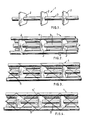
- the method according to the invention begins with the manufacture of the carcase 1.
- Spacer plates 2 of a composite material of glassfibres and a thermoplastics resin are spaced at equal intervals along a shaft or tube 3.
- the shaft or tube 3 is arranged on a vertically rotatable turntable to increase the accessibility of the beam during manufacture.
- Elongate members in the form of tubes 4 also of a similar composite material are then arranged in predetermined positions in relation to the spacer plates 2.
- a plurality of wires 5 is then wound in a predetermined pattern around the carcase 1. This pattern may be a spiral pattern.
- Each tube 4 is contacted by a wire 5 in the plane of each spacer plate 2.
- the edges of each spacer plate 2 are crossed by a wire 5 between adjacent tubes 4.
- Further wires 5′ are then added to increase the stability and strength of the beam.
- the further wires 5′ are also wound in a spiral pattern, preferably rotating in the opposite direction to the first wires 5.
- the further wires 5′ also contact the tubes 4 in the plane of each spacer plate 2 and the edges of the spacer plates 2 are each crossed by a wire 5′ between adjacent tubes 4.
- Each of the wires 5,5′ has a core of electrically conducting material and a coating of a thermoplastics material.
- the wires 5, 5′ are made to adhere to the carcase 1 by passing a current through the core such that the thermoplastics coating is melted.
- the thermoplastics resin of the composite material of the tubes 4 and spacer plates 2 is also melted in the region adjacent each point of contact with the wires 5,5′. When the current is cut off and the wires 5,5′ cool, the thermoplastics resin sets joining the wire 5,5′ to the tubes 4 and the spacer plates 2.
- elongate members described above are tubular, it would be equally acceptable to utilise solid bars of relatively lightweight construction or tubular members filled with foam or synthetic material. Different arrangements of elongate members around the spacer plates are possible: the arrangement shown in the representations is by way of example only. The invention is not limited to elongate members of composite material - it is envisaged that elongate members comprising thin-walled steel or aluminium tubes would also be suitable.
- the flexible elements may be wires, lines or bands of steel or other metal, or could comprise non-metallic materials of high tensile strength such as carbon- or glass-reinforced resin.
- the flexible elements may have a coating of a plastics material and may be adhered to the carcase by means other than those described above, e.g. by direct application of heat to to thermoplastics coating.
- the flexible elements may be fixed to the carcase at either end of the beam or at periodical intervals. The fixing may take any suitable form, e.g. by tying, welding or repeated winding. Patterns other than spirals may be used, provided that the elongate members are contacted by the flexible elements in the plane of each spacer plate.
- a single flexible element refers to a wire or the like running from one end of the beam to the other. It would, of course, be possible to arrange for successively wound flexible elements to be connected end to end and wound back and forth along the beam.
Landscapes
- Engineering & Computer Science (AREA)
- Architecture (AREA)
- Civil Engineering (AREA)
- Structural Engineering (AREA)
- Chemical & Material Sciences (AREA)
- Composite Materials (AREA)
- Rod-Shaped Construction Members (AREA)
- Laminated Bodies (AREA)
- Slide Fasteners, Snap Fasteners, And Hook Fasteners (AREA)
- Diaphragms For Electromechanical Transducers (AREA)
- External Artificial Organs (AREA)
- Glass Compositions (AREA)
- Inorganic Insulating Materials (AREA)
- Electrical Discharge Machining, Electrochemical Machining, And Combined Machining (AREA)
- Mechanical Treatment Of Semiconductor (AREA)
- Manufacture Of Motors, Generators (AREA)
- Superconductors And Manufacturing Methods Therefor (AREA)
- Lining Or Joining Of Plastics Or The Like (AREA)
- Electronic Switches (AREA)
- Control Of El Displays (AREA)
- Moulding By Coating Moulds (AREA)
- Ropes Or Cables (AREA)
Priority Applications (1)
| Application Number | Priority Date | Filing Date | Title |
|---|---|---|---|
| AT88903297T ATE70877T1 (de) | 1987-04-09 | 1988-04-11 | Herstellungsverfahren eines fachwerktraegers. |
Applications Claiming Priority (2)
| Application Number | Priority Date | Filing Date | Title |
|---|---|---|---|
| GB8708500 | 1987-04-09 | ||
| GB08708500A GB2204614A (en) | 1987-04-09 | 1987-04-09 | Manufacture of a truss beam of composite materials |
Publications (2)
| Publication Number | Publication Date |
|---|---|
| EP0355103A1 EP0355103A1 (en) | 1990-02-28 |
| EP0355103B1 true EP0355103B1 (en) | 1991-12-27 |
Family
ID=10615530
Family Applications (1)
| Application Number | Title | Priority Date | Filing Date |
|---|---|---|---|
| EP88903297A Expired - Lifetime EP0355103B1 (en) | 1987-04-09 | 1988-04-11 | A method of manufacturing a truss beam |
Country Status (13)
| Country | Link |
|---|---|
| EP (1) | EP0355103B1 (da) |
| JP (1) | JPH03500068A (da) |
| KR (1) | KR890700726A (da) |
| CN (1) | CN88102214A (da) |
| AT (1) | ATE70877T1 (da) |
| AU (1) | AU616887B2 (da) |
| BR (1) | BR8807454A (da) |
| DE (1) | DE3867235D1 (da) |
| DK (1) | DK496589A (da) |
| FI (1) | FI894791A0 (da) |
| GB (1) | GB2204614A (da) |
| NO (1) | NO885476L (da) |
| WO (1) | WO1988008064A1 (da) |
Families Citing this family (5)
| Publication number | Priority date | Publication date | Assignee | Title |
|---|---|---|---|---|
| DE9312391U1 (de) * | 1993-08-14 | 1993-10-21 | Menzel, Hans-Claus, Dr., 70619 Stuttgart | Verstrebung der Mittelstütze eines Verbundpfeilers |
| DE29907874U1 (de) * | 1999-05-04 | 2000-09-14 | Hupperich, Werner, 53804 Much | Montagevorrichtung für Bauzwecke |
| AUPQ356699A0 (en) * | 1999-10-21 | 1999-11-11 | Bhp Steel (Rp) Pty Ltd | A rollable mesh apparatus |
| AU782363B2 (en) * | 1999-10-21 | 2005-07-21 | Onesteel Reinforcing Pty Limited | A rollable mesh apparatus |
| US8919071B2 (en) * | 2012-12-19 | 2014-12-30 | Patco, Llc | Truss configuration |
Family Cites Families (4)
| Publication number | Priority date | Publication date | Assignee | Title |
|---|---|---|---|---|
| US3501880A (en) * | 1967-11-08 | 1970-03-24 | Lawrence R Bosch | Captive column structure |
| CH636929A5 (de) * | 1979-04-18 | 1983-06-30 | Pantex Stahl Ag | Gittertraeger fuer den untertag-strecken- und -schachtausbau. |
| US4566247A (en) * | 1983-08-03 | 1986-01-28 | Overbo Gordon I | Captive column |
| DE3436882A1 (de) * | 1984-07-27 | 1986-01-30 | Burger, Frank, 8000 München | Rahmensystem, insbesondere fuer gestelle und den innenausbau |
-
1987
- 1987-04-09 GB GB08708500A patent/GB2204614A/en active Pending
-
1988
- 1988-04-09 CN CN8888102214A patent/CN88102214A/zh active Pending
- 1988-04-11 DE DE8888903297T patent/DE3867235D1/de not_active Expired - Fee Related
- 1988-04-11 EP EP88903297A patent/EP0355103B1/en not_active Expired - Lifetime
- 1988-04-11 FI FI894791A patent/FI894791A0/fi not_active IP Right Cessation
- 1988-04-11 AU AU15779/88A patent/AU616887B2/en not_active Ceased
- 1988-04-11 WO PCT/GB1988/000279 patent/WO1988008064A1/en not_active Ceased
- 1988-04-11 JP JP63503063A patent/JPH03500068A/ja active Pending
- 1988-04-11 AT AT88903297T patent/ATE70877T1/de not_active IP Right Cessation
- 1988-04-11 BR BR888807454A patent/BR8807454A/pt unknown
- 1988-12-08 KR KR1019880701625A patent/KR890700726A/ko not_active Withdrawn
- 1988-12-09 NO NO88885476A patent/NO885476L/no unknown
-
1989
- 1989-10-06 DK DK496589A patent/DK496589A/da not_active Application Discontinuation
Also Published As
| Publication number | Publication date |
|---|---|
| AU616887B2 (en) | 1991-11-14 |
| GB2204614A (en) | 1988-11-16 |
| CN88102214A (zh) | 1988-10-26 |
| BR8807454A (pt) | 1990-05-15 |
| WO1988008064A1 (en) | 1988-10-20 |
| DK496589D0 (da) | 1989-10-06 |
| FI894791A7 (fi) | 1989-10-09 |
| DE3867235D1 (de) | 1992-02-06 |
| ATE70877T1 (de) | 1992-01-15 |
| DK496589A (da) | 1989-10-06 |
| FI894791A0 (fi) | 1989-10-09 |
| JPH03500068A (ja) | 1991-01-10 |
| NO885476D0 (no) | 1988-12-09 |
| NO885476L (no) | 1989-02-01 |
| AU1577988A (en) | 1988-11-04 |
| KR890700726A (ko) | 1989-04-27 |
| EP0355103A1 (en) | 1990-02-28 |
| GB8708500D0 (en) | 1987-05-13 |
Similar Documents
| Publication | Publication Date | Title |
|---|---|---|
| DE68917184T2 (de) | Verfahren zur Herstellung eines geschweissten, wabenförmigen Kernes. | |
| US4685608A (en) | Soldering apparatus | |
| EP1112448B2 (en) | Lightning protection for wind turbine blade | |
| US4538131A (en) | Air-core choke coil | |
| US3627903A (en) | Woven cable harness assembly and method of making same | |
| EP1930914A2 (en) | Composite reinforced electrical transmission conductor | |
| EP0244120A2 (en) | Composite element | |
| JPH0453826B2 (da) | ||
| EP0355103B1 (en) | A method of manufacturing a truss beam | |
| US4435242A (en) | Elongate structure | |
| DE69308208T2 (de) | Heizvorrichtung zum thermoplastischen schweissen | |
| DE10118816A1 (de) | Herstellungsverfahren für eine anisotrope leitfähige Folie und nach diesem Verfahren hergestellte anisotrope leitfähige Folie | |
| EP0290677A1 (de) | Verfahren zur Isolierung von Bauteilen | |
| WO1999041061A1 (en) | Continuous process for forming structure suitable for use as a core member | |
| DE4234129A1 (de) | Mehrphasige elektrische Maschine mit zusammenmontierbaren Leiterlagen | |
| JP3426089B2 (ja) | 繊維強化プラスチック製のハニカムコア | |
| EP0029910B1 (de) | Verfahren zum Verkleben von Gegenständen mittels eines heiBhärtbaren Klebers | |
| DE3939570C2 (de) | Anbohrschelle für Kunststoffrohre | |
| EP0924054A2 (en) | Welding element for thermoplastic parts | |
| DE4234175A1 (de) | Mehrphasige elektrische Maschine mit schleifenlos montierten Leitersträngen | |
| GB2237442A (en) | Flat cable | |
| DE3523929A1 (de) | Induktiv erhitzbare vorrichtung | |
| EP0205459A1 (de) | Scheibenläufer für eine elektrische axialluftspaltmaschine | |
| US3739203A (en) | Linear induction motor armatures | |
| JPS6178011A (ja) | 製織ケ−ブル |
Legal Events
| Date | Code | Title | Description |
|---|---|---|---|
| PUAI | Public reference made under article 153(3) epc to a published international application that has entered the european phase |
Free format text: ORIGINAL CODE: 0009012 |
|
| 17P | Request for examination filed |
Effective date: 19891009 |
|
| AK | Designated contracting states |
Kind code of ref document: A1 Designated state(s): AT BE CH DE FR GB IT LI LU NL SE |
|
| 17Q | First examination report despatched |
Effective date: 19900710 |
|
| GRAA | (expected) grant |
Free format text: ORIGINAL CODE: 0009210 |
|
| AK | Designated contracting states |
Kind code of ref document: B1 Designated state(s): AT BE CH DE FR GB IT LI LU NL SE |
|
| PG25 | Lapsed in a contracting state [announced via postgrant information from national office to epo] |
Ref country code: IT Free format text: LAPSE BECAUSE OF FAILURE TO SUBMIT A TRANSLATION OF THE DESCRIPTION OR TO PAY THE FEE WITHIN THE PRESCRIBED TIME-LIMIT;WARNING: LAPSES OF ITALIAN PATENTS WITH EFFECTIVE DATE BEFORE 2007 MAY HAVE OCCURRED AT ANY TIME BEFORE 2007. THE CORRECT EFFECTIVE DATE MAY BE DIFFERENT FROM THE ONE RECORDED. Effective date: 19911227 Ref country code: CH Effective date: 19911227 Ref country code: LI Effective date: 19911227 Ref country code: NL Effective date: 19911227 Ref country code: BE Effective date: 19911227 Ref country code: AT Effective date: 19911227 |
|
| REF | Corresponds to: |
Ref document number: 70877 Country of ref document: AT Date of ref document: 19920115 Kind code of ref document: T |
|
| REF | Corresponds to: |
Ref document number: 3867235 Country of ref document: DE Date of ref document: 19920206 |
|
| REG | Reference to a national code |
Ref country code: CH Ref legal event code: PL |
|
| PG25 | Lapsed in a contracting state [announced via postgrant information from national office to epo] |
Ref country code: LU Free format text: LAPSE BECAUSE OF NON-PAYMENT OF DUE FEES Effective date: 19920430 |
|
| ET | Fr: translation filed | ||
| NLV1 | Nl: lapsed or annulled due to failure to fulfill the requirements of art. 29p and 29m of the patents act | ||
| PLBE | No opposition filed within time limit |
Free format text: ORIGINAL CODE: 0009261 |
|
| STAA | Information on the status of an ep patent application or granted ep patent |
Free format text: STATUS: NO OPPOSITION FILED WITHIN TIME LIMIT |
|
| 26N | No opposition filed | ||
| REG | Reference to a national code |
Ref country code: GB Ref legal event code: 732E |
|
| REG | Reference to a national code |
Ref country code: FR Ref legal event code: TP |
|
| EAL | Se: european patent in force in sweden |
Ref document number: 88903297.5 |
|
| PGFP | Annual fee paid to national office [announced via postgrant information from national office to epo] |
Ref country code: GB Payment date: 19990305 Year of fee payment: 12 |
|
| PGFP | Annual fee paid to national office [announced via postgrant information from national office to epo] |
Ref country code: FR Payment date: 19990330 Year of fee payment: 12 |
|
| PGFP | Annual fee paid to national office [announced via postgrant information from national office to epo] |
Ref country code: SE Payment date: 19990408 Year of fee payment: 12 |
|
| PGFP | Annual fee paid to national office [announced via postgrant information from national office to epo] |
Ref country code: DE Payment date: 19990428 Year of fee payment: 12 |
|
| PG25 | Lapsed in a contracting state [announced via postgrant information from national office to epo] |
Ref country code: GB Free format text: LAPSE BECAUSE OF NON-PAYMENT OF DUE FEES Effective date: 20000411 |
|
| PG25 | Lapsed in a contracting state [announced via postgrant information from national office to epo] |
Ref country code: SE Free format text: LAPSE BECAUSE OF NON-PAYMENT OF DUE FEES Effective date: 20000412 |
|
| GBPC | Gb: european patent ceased through non-payment of renewal fee |
Effective date: 20000411 |
|
| EUG | Se: european patent has lapsed |
Ref document number: 88903297.5 |
|
| PG25 | Lapsed in a contracting state [announced via postgrant information from national office to epo] |
Ref country code: FR Free format text: LAPSE BECAUSE OF NON-PAYMENT OF DUE FEES Effective date: 20001229 |
|
| PG25 | Lapsed in a contracting state [announced via postgrant information from national office to epo] |
Ref country code: DE Free format text: LAPSE BECAUSE OF NON-PAYMENT OF DUE FEES Effective date: 20010201 |
|
| REG | Reference to a national code |
Ref country code: FR Ref legal event code: ST |