EP0355216B1 - Porte-outil de coupe - Google Patents
Porte-outil de coupe Download PDFInfo
- Publication number
- EP0355216B1 EP0355216B1 EP88307536A EP88307536A EP0355216B1 EP 0355216 B1 EP0355216 B1 EP 0355216B1 EP 88307536 A EP88307536 A EP 88307536A EP 88307536 A EP88307536 A EP 88307536A EP 0355216 B1 EP0355216 B1 EP 0355216B1
- Authority
- EP
- European Patent Office
- Prior art keywords
- insert
- clamping
- ball
- tool holder
- groove
- Prior art date
- Legal status (The legal status is an assumption and is not a legal conclusion. Google has not performed a legal analysis and makes no representation as to the accuracy of the status listed.)
- Expired - Lifetime
Links
- 238000005520 cutting process Methods 0.000 title claims description 37
- 230000000284 resting effect Effects 0.000 claims description 3
- 238000006073 displacement reaction Methods 0.000 claims description 2
- 239000002184 metal Substances 0.000 description 8
- 229910052751 metal Inorganic materials 0.000 description 8
- 238000003754 machining Methods 0.000 description 2
- 230000000712 assembly Effects 0.000 description 1
- 238000000429 assembly Methods 0.000 description 1
- 230000005484 gravity Effects 0.000 description 1
- 230000002452 interceptive effect Effects 0.000 description 1
- 150000002739 metals Chemical class 0.000 description 1
Images



Classifications
-
- B—PERFORMING OPERATIONS; TRANSPORTING
- B23—MACHINE TOOLS; METAL-WORKING NOT OTHERWISE PROVIDED FOR
- B23B—TURNING; BORING
- B23B27/00—Tools for turning or boring machines; Tools of a similar kind in general; Accessories therefor
- B23B27/14—Cutting tools of which the bits or tips or cutting inserts are of special material
- B23B27/16—Cutting tools of which the bits or tips or cutting inserts are of special material with exchangeable cutting bits or cutting inserts, e.g. able to be clamped
- B23B27/1666—Cutting tools of which the bits or tips or cutting inserts are of special material with exchangeable cutting bits or cutting inserts, e.g. able to be clamped with plate-like cutting inserts clamped by a clamping member acting almost perpendicularly on chip-forming plane
-
- B—PERFORMING OPERATIONS; TRANSPORTING
- B23—MACHINE TOOLS; METAL-WORKING NOT OTHERWISE PROVIDED FOR
- B23B—TURNING; BORING
- B23B27/00—Tools for turning or boring machines; Tools of a similar kind in general; Accessories therefor
- B23B27/14—Cutting tools of which the bits or tips or cutting inserts are of special material
- B23B27/16—Cutting tools of which the bits or tips or cutting inserts are of special material with exchangeable cutting bits or cutting inserts, e.g. able to be clamped
- B23B27/1659—Cutting tools of which the bits or tips or cutting inserts are of special material with exchangeable cutting bits or cutting inserts, e.g. able to be clamped with plate-like exchangeable cutting inserts
-
- B—PERFORMING OPERATIONS; TRANSPORTING
- B23—MACHINE TOOLS; METAL-WORKING NOT OTHERWISE PROVIDED FOR
- B23B—TURNING; BORING
- B23B2260/00—Details of constructional elements
- B23B2260/022—Balls
-
- Y—GENERAL TAGGING OF NEW TECHNOLOGICAL DEVELOPMENTS; GENERAL TAGGING OF CROSS-SECTIONAL TECHNOLOGIES SPANNING OVER SEVERAL SECTIONS OF THE IPC; TECHNICAL SUBJECTS COVERED BY FORMER USPC CROSS-REFERENCE ART COLLECTIONS [XRACs] AND DIGESTS
- Y10—TECHNICAL SUBJECTS COVERED BY FORMER USPC
- Y10T—TECHNICAL SUBJECTS COVERED BY FORMER US CLASSIFICATION
- Y10T407/00—Cutters, for shaping
- Y10T407/22—Cutters, for shaping including holder having seat for inserted tool
- Y10T407/2222—Tool adjustable relative to holder
- Y10T407/2248—Pivoted tool
-
- Y—GENERAL TAGGING OF NEW TECHNOLOGICAL DEVELOPMENTS; GENERAL TAGGING OF CROSS-SECTIONAL TECHNOLOGIES SPANNING OVER SEVERAL SECTIONS OF THE IPC; TECHNICAL SUBJECTS COVERED BY FORMER USPC CROSS-REFERENCE ART COLLECTIONS [XRACs] AND DIGESTS
- Y10—TECHNICAL SUBJECTS COVERED BY FORMER USPC
- Y10T—TECHNICAL SUBJECTS COVERED BY FORMER US CLASSIFICATION
- Y10T407/00—Cutters, for shaping
- Y10T407/22—Cutters, for shaping including holder having seat for inserted tool
- Y10T407/2272—Cutters, for shaping including holder having seat for inserted tool with separate means to fasten tool to holder
-
- Y—GENERAL TAGGING OF NEW TECHNOLOGICAL DEVELOPMENTS; GENERAL TAGGING OF CROSS-SECTIONAL TECHNOLOGIES SPANNING OVER SEVERAL SECTIONS OF THE IPC; TECHNICAL SUBJECTS COVERED BY FORMER USPC CROSS-REFERENCE ART COLLECTIONS [XRACs] AND DIGESTS
- Y10—TECHNICAL SUBJECTS COVERED BY FORMER USPC
- Y10T—TECHNICAL SUBJECTS COVERED BY FORMER US CLASSIFICATION
- Y10T82/00—Turning
- Y10T82/25—Lathe
- Y10T82/2585—Tool rest
Definitions
- This invention relates to a cutting tool assembly wherein a replaceable cutting insert is releasably clamped in an insert seat formed in a tool holder.
- the replaceable cutting insert is generally of the indexable kind and it is therefore an important requirement for the clamping arrangement that as each cutting edge is indexed into position, it should occupy the exact same position as that occupied by the preceding edge. Furthermore, the clamping arrangement must be such as not to constitute an undesired interference with the controlled flow of the chips produced during cutting.
- FR-A-2 327 839 discloses a clamping arrangement wherein a centrally apertured insert is closely fitted on a mounting pin extending from a tool holder and the insert is pressed against the pin by means of a pair of radially directed pressure members (which can consist of aligned balls) means being provided to displace the balls thereby pressing the insert against the pin.
- a pair of radially directed pressure members which can consist of aligned balls
- a clamping arrangement for clamping a cutting insert (12) to a tool holder (10) wherein said tool holder (10) is formed at an end thereof with an insert seat (13) defined by a base surface (16) and a transverse side surface (22); a mounting pin (14) secured to said tool holder (10) and extending out of said base surface (16) so as to have mounted thereon a centrally apertured cutting insert (12); a ball guide groove (18) formed in said tool holder (10); a plurality of clamping balls (32) located in said groove (18); a ball displacing member (40) articulated to said tool holder (10) and juxtaposed with respect to said groove (18) so as to bear on said innermost clamping ball (32) and displacing means (45) for displacing said member (40) towards said tool holder (10) so as to displace said innermost clamping ball (32) into displacing said outermost clamping ball (32) outwardly with respect to said side surface (22
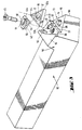
- FIGs. 1 and 2 are side and top views of the novel holder 10, designed to support and rigidly secure thereto a cutting insert 12, while Fig. 3 is an expanded isometric view of the holder 10 and the insert 12.
- like elements are designated by like numerals.
- the holder 10 has a recess 13 (see Fig. 3) constituting a seat and is of the pin supporting type, in that it has a pin 14 which is typically cylindrical and which extends upwardly, perpendicular to a flat surface 16, hereafter also referred to as the first surface, designed to support thereon the insert 12.
- the latter is shown in the shape of an equilateral triangle with cutting edges 12a-12c, and with a central hole or cavity 17 which extends perpendicularly from the insert's top side 19 to its bottom side 21, which rests on surface 16.
- the recess 13 is typically triangularly shaped, so that surface 16 extends from a front tip 16t on which the insert's cutting edge, e.g. 12a, rests, to a rearward edge from which a side wall 22 of the holder extends upwardly.
- the insert 12 When the insert 12 rests on surface 16, with edge 12a pointed as the cutting edge, the insert's side 23, extending between cutting edges 12b and 12c, lies adjacent and substantially parallel to side wall 22, hereafter simply referred to as side 22. As long as a locking force is not applied to the insert, it is freely supported on surface 16 about pin 14, in that it is free to partially pivot and move with respect to the pin as well as become disengaged from surface 16.
- a locking force is applied to the insert 12 by means of an element which is projectable out of side 22 to push against side 23 of the insert so as to apply a rotational force or torque to the insert. Consequently, the insert pivots about pin 14, as represented in Fig. 2 by arrow 25. As the insert pivots, since its side 23 is very close to side 22, it finally abuts side 22, thus terminating the insert's pivoting motion. However, the locking force also pushes the insert slightly forward until one or more surface points of its cavity 17 presses against pin 14. Thus the insert becomes locked to or secured in the holder by being pressed against it at at least two spaced apart points, in addition to being pressed by the element which causes its initial pivoting. That is, the insert is pressed against side 22 and against pin 14 and against the element which caused it to pivot.
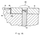
- side 22 preferably is tilted slightly forward so that when the locking force is applied to the insert as a result of the fact that the point of contact between sides 22 and 23 as represented in Fig. 1A by R1 is at a higher level or plane than the point(s) of contact between pin 14 and hole 17 as represented by R2, a downward-pointing moment is produced, represented in Fig. 1A by arrow 24.
- This moment causes the insert to be pressed tightly against the front part of the holder surface 16, and thus reduces the likelihood that the insert will move with respect to the holder, due to forces applied to the insert's cutting edge by the workpiece, which is being cut.
- a unique locking arrangement is employed to apply the locking force to the insert so as to lock it to the holder.
- the locking force can be speedily and easily released to unlock the insert.
- the insert Once unlocked, the insert can be pulled up and rotated so as to position another of its cutting edges at the cutting position. Similarly, one insert can be easily replaced by another. Due to the novel holder, once it has been properly indexed for a cutting operation the changing of cutting edges at the cutting position does not affect the indexing, in that each newly positioned cutting edge assumes the exact location at the cutting position, previously occupied by a previously-positioned cutting edge.
- the unique arrangement is positionable to apply a clamping force to the insert top, without interfering with metal ribbon flow.
- metal ribbons are referred to as chips.
- Such clamping force is provided to further increase the pressing of the insert against tool surface 16 in addition to that provided by the downward directed moment, represented by arrow 24.
- Such additional force may be found to be desirable to further secure the insert in the holder, particularly when machining in extremely difficult conditions, e.g. hard metals, intermittent cutting, or unstable conditions.
- a second surface 26 extends in a direction away from surface 16.
- a channel 18 is formed to extend from surface 26 to side 22.
- the channel 18 constitutes a ball guide groove designed to accommodate therein several hardened metal balls of the bearing type.
- the channel is wide enough for the balls to move therein.
- the channel end, exposed through surface 26, hereafter referred to as the top end is large enough for the balls to be inserted into the channel therethrough, while the channel end exposed through side 22, hereafter referred to as the bottom end, is narrower than the ball diameter.
- balls cannot exit through the channel bottom end.
- a portion of the ball closest to the bottom end e.g. Ball 32 can extend outwardly from the channel.
- only less than half of ball 32 can extend out of the channel.
- the channel length and the balls' sizes are chosen so that even when ball 32 extends outwardly to the maximum extent possible, part of ball 31 protrudes through and is exposed above surface 26. Furthermore, the channel is shaped to insure that even when a large downward force is applied to ball 31, its centre is always substantially above that of the centre of ball 32. Thus ball 31 always partially rides on and presses against ball 32.
- Fig. 4 to which reference is made. The latter is a cross-sectional view along lines 4-4 in Fig. 2.
- the bottom of the channel 28 is provided with a ledge 28x, to prevent ball 31 from lowering to the level of ball 32, even when a downward force is applied to ball 31, as indicated by arrow 35.
- the downward force on the ball 31 will hereafter be referred to as external force 35 or locking force 35.
- the two balls 31 and 32 are inserted into channel 28 through the top end.
- the balls remain in the channel, and cannot exit the bottom end at holder side 22, since the bottom end is narrower than the diameter of ball 32.
- part of ball 32 is exposed through the bottom end while part of the ball 31 is exposed through the top end at surface 26.
- the only force which is applied to ball 32 by ball 31 is due to gravity.
- the balls fit loosely in the channel 28. Even though part of ball 32 may extend out of the channel, it does not interfere with placing the insert 12 over the pin 14, to be supported on surface 16.
- insert side 23 When insert 12 is supported on surface 16, the insert side 23 is close to holder side 22 and the surface of the protruding ball 32. As a downward external force 35 is applied to ball 31 it exerts a force on ball 32, urging the latter to extend farther out of the channel bottom end. Since the width of the latter is less than the diameter of ball 32, less than half of ball 32 can protrude out of the channel. When the external force 35 is applied to ball 31, ball 32 extends farther outwardly of the channel and finally comes in contact wit6h insert side 23. When the force 35 on ball 31 is sufficiently large the ball 32 is urged outwardly to an extent sufficient to cause insert 12 to pivot and be locked in the holder, as previously described.
- the locking of the insert is achievable by applying the external force to an element, other than the insert itself, to achieve insert locking. Furthermore, the force is applied at a point away from the insert top surface 19. Thus, the latter is unobstructed by any clamping elements whatsoever, and therefore any means therein are free to properly direct metal ribbons or chips away from the cutting position.
- a washer-like member which acts as a clamp, and will be hereafter referred to as the clamp member or simply member 40.
- the member 40 has a flat bottom side 42 (see Fig. 6) with a central hole 44 extending from its bottom side 42 to its top, in order to enable a bolt 45 to extend therethrough.
- the clamp member 40 is pressed against the holder 10, as well as against ball 31 by bolt 45 being threaded tightly within threaded hole 47 in holder surface 26.
- the top end of hole 44 is flared outwardly to accommodate therein the bolt's flat head.
- member 40 can choose the outer dimension of member 40 to be sufficiently large to come in contact with protruding ball 31 when the member 40 is tightened by bolt 45 toward surface 26. Since the ball 31 always protrudes out of surface 26 the member's bottom side 42 can never lie flat against surface 26. However, even when disposed at an angle, side 42 can press on ball 31 when it is urged toward surface 26, and yet be in contact with surface 26. By being pressed against ball 31 member 40 effectively applies the external force 35 to ball 31 which is necessary to push ball 32 farther outwardly and thus lock the insert, as herebefore explained.
- the member 40 may be truncated, to form a truncated edge 40x and be aligned so that when pressed or clamped by bolt 45, even though it presses on ball 31, it does not extend beyond holder side 22, so as not to protrude over the lockable insert. This facilitates the changing of the cutting edge at the cutting position or insert replacement.
- the member 40 may be designed to assume either of two clamped positions, one in which, due to the truncated member edge 40x, it does not project beyond side 22 and thus does not extend over the insert, and one in which part of the member's bottom side 42 actually presses down on the insert, to provide an additional securing force thereto.
- the holder 10 is shaped to have a ledge 50 with a top side 51 and a curved side 52 which is at the edge of top surface 26.
- the curved side 52 acts as a cam and thus will be referred to as the cam 52.
- Member 40 is shaped to have two cam following sides or faces 55 and 56 which are designed to follow cam 52. Briefly, faces 55 and 56 are formed in a side of member 40 which is recessed inwardly toward hole 44, so that part of the member top defines a ledge 58, which extends outwardly.
- Face 55 is effectively positioned opposite truncated edge 40x so that when face 55 follows the cam 52 the truncated edge 40x of member 40 is effectively parallel with side wall 22. That is, the member 40 does not extend over the insert, as shown in Figs. 1 and 2. In this position member 40, in addition to pressing on ball 31 and thus resting on it, is pressed against holder surface 26 and ledge 50. On the other hand, when face 56 follows the cam 52 and member 40 is tightened to the holder 10 by bolt 45, the end of the truncated edge 40x, opposite face 56, is effectively in contact with the top side of the insert and applies a downward clamping force thereto, as shown in Figs. 5 and 6.
- the member 40 is pressed against substantially three point contacts.
- One is the top ball 31, the second is the top side 19 of the insert, and the third is at or near the edge between faces 51 and 52 of ledge 50.
- the member is securely held by being pressed against three spaced apart points, one being the top of ball 31, to which the external force is applied by member 40, and which causes ball 32 to apply the locking force to the insert.
- the hole 44 in member 40 in addition to accommodating the bolt 45 therethrough, is shaped (see Fig. 6) to accommodate a spring washer 62 which is secured to the bolt just below its head.
- member 40 fits loosely below the bolt head.
- the loose member 40 is aligned around the bolt so that cam following side 55 abuts against cam 52, and edge 40x is substantially parallel to side 22.
- cam following face 56 rather than face 55, tends to abut against cam 52.
- member 40 assumes the position, as shown in Figs. 5 and 6. That is, an end of its edge 40x presses directly on insert 12, thereby providing the additional clamping force thereto.
- this additional clamping force is not necessary for most machining operations in order to secure the insert in the holder, since the former is sufficiently secured by the locking force provided by ball 32.
- the additional force may be provided by the member 40, acting as a top clamp on only a limited surface area of the insert.
Landscapes
- Engineering & Computer Science (AREA)
- Mechanical Engineering (AREA)
- Cutting Tools, Boring Holders, And Turrets (AREA)
- Milling Processes (AREA)
- Gripping On Spindles (AREA)
Claims (4)
- Dispositif de serrage pour outil tranchant destiné à immobiliser un élément coupant (12) sur un support d'outil (10) où ce support d'outil (10) présente à l'une de ses extrémités un siège (13) à élément coupant délimité par une surface de base (16) et une surface latérale transversale (22) ; un pion de montage (14) fixé à ce support d'outil (10) et saillant sur cette surface de base (16) de manière à pouvoir recevoir un élément coupant à orifice central ; une gorge de guidage (18) de billes ménagée dans ce support d'outils (10) ; des billes (32) d'immobilisation logées dans cette gorge (18) ; un organe (40) de déplacement des billes articulé à ce support d'outil (10) et juxtaposé à cette gorge (18) de manière à porter sur la bille (32) la plus à l'intérieur et des moyens de déplacement (45) pour mouvoir cet organe (40) vers ce support d'outil (10), afin d'agir sur cette bille (32) la plus à l'intérieur pour chasser la bille (32) la plus à l'extérieur en saillie relativement à cette surface latérale (22) de manière qu'un élément coupant (12) placé sur ce pion (14) et reposant sur cette surface de base (16) est appliquée en serrage contre celui-ci, dispositif caractérisé en ce que cette gorge (18) présente une ouverture supérieure sur toute sa longueur ménagée dans une surface (26) supérieure du support d'outil (10) voisine du siège (13) à élément coupant pour permettre une insertion directe de ces billes (32) dans cette gorge (18) dont une première extrémité interne sert de portée pour la bille (32) la plus à l'intérieur et dont une seconde extrémité externe débouche dans cette surface latérale transversale (22) avec une dimension transversale inférieure au diamètre de celles de ces billes (32) la plus à l'extérieur, ainsi qu'un fond (28) distant de cette surface supérieure (28) dans la zone de cette première extrémité d'une première valeur moindre que le diamètre de la bille (32) la plus à l'intérieur et dans la zone de cette seconde extrémité d'une seconde valeur, ce dispositif étant tel qu'un élément coupant (12) peut être placé sur ce pion (14) de manière à ce qu'il soit doué d'un degré de liberté limité relativement à celui-ci, cette bille (32) la plus à l'extérieur étant apte à porter contre un bord latéral de cet élément coupant (12) afin que lors d'un déplacement vers l'extérieur de cette bille (32) la plus à l'extérieur cet élément coupant tourne pour venir en contact d'immobilisation avec ces surfaces latérale et de base (22, 16).
- Dispositif selon la revendication 1, caractérisé en ce que cet organe de déplacement (40) est une rondelle (40) discoïde montée sur ce support d'outil (10) au-dessus de cette gorge à billes (18).
- Dispositif selon la revendication 2, caractérisé en ce que cette rondelle (40) est configurée pour rester à distance de cet élément coupant (12)
- Dispositif selon la revendication 2, caractérisé en ce que ces moyens de déplacement (45) comprennent une vis (45) traversant dans cette rondelle (40) et engagée dans un trou (47) chanfreiné du support d'outil (10).
Priority Applications (1)
| Application Number | Priority Date | Filing Date | Title |
|---|---|---|---|
| DE8888307536T DE3875615T2 (de) | 1988-08-15 | 1988-08-15 | Schneidwerkzeughalter. |
Applications Claiming Priority (1)
| Application Number | Priority Date | Filing Date | Title |
|---|---|---|---|
| US07/232,908 US4876932A (en) | 1988-08-16 | 1988-08-16 | Cutting tool holder |
Publications (2)
| Publication Number | Publication Date |
|---|---|
| EP0355216A1 EP0355216A1 (fr) | 1990-02-28 |
| EP0355216B1 true EP0355216B1 (fr) | 1992-10-28 |
Family
ID=22875078
Family Applications (1)
| Application Number | Title | Priority Date | Filing Date |
|---|---|---|---|
| EP88307536A Expired - Lifetime EP0355216B1 (fr) | 1988-08-15 | 1988-08-15 | Porte-outil de coupe |
Country Status (3)
| Country | Link |
|---|---|
| US (1) | US4876932A (fr) |
| EP (1) | EP0355216B1 (fr) |
| DE (1) | DE3875615T2 (fr) |
Families Citing this family (18)
| Publication number | Priority date | Publication date | Assignee | Title |
|---|---|---|---|---|
| US5167473A (en) * | 1991-06-24 | 1992-12-01 | Allied-Signal Inc. | Unidirectional insert lock |
| US5209146A (en) * | 1991-10-15 | 1993-05-11 | Kennametal Inc. | Ball lock apparatus for small diameter toolholders |
| US5536120A (en) * | 1994-05-11 | 1996-07-16 | Miller; Arthur W. | Turning tool holder having rotatably adjustable clamping mechanism |
| US5868530A (en) * | 1995-10-12 | 1999-02-09 | Shouse; Virgil | Cutting tool |
| US5647701A (en) * | 1995-12-13 | 1997-07-15 | Tempel; Daryl K. | Multiple spindle screw machine box tool insert holder |
| US5913643A (en) * | 1997-04-22 | 1999-06-22 | Kennametal Inc. | Adjustable lead angle chamfering toolholder |
| US6155753A (en) * | 1999-07-15 | 2000-12-05 | Chang; Hsin-Tien | Fine adjusting mechanism for a cutting tool |
| IL131463A (en) * | 1999-08-18 | 2003-05-29 | Iscar Ltd | Cutting insert pocket |
| IL153796A0 (en) * | 2003-01-05 | 2003-07-31 | Iscar Ltd | Cutting insert holder |
| DE20303316U1 (de) * | 2003-02-28 | 2003-04-30 | Gühring, Jörg, Dr., 72458 Albstadt | Drehangetriebenes Zerspanungswerkzeug |
| US7789598B2 (en) * | 2005-07-12 | 2010-09-07 | Kyocera Corporation | Surface coated cutting tool |
| US7429150B2 (en) * | 2006-05-31 | 2008-09-30 | Kennametal Inc. | Tool holder with spherical contact points |
| US7422395B2 (en) * | 2006-11-15 | 2008-09-09 | Hsien-Jen Huang | Tool holder structure |
| JP5323149B2 (ja) * | 2011-08-19 | 2013-10-23 | 三星ダイヤモンド工業株式会社 | ホイールユニット |
| US8821079B2 (en) * | 2012-03-06 | 2014-09-02 | Iscar, Ltd. | Cutting tool and cutting insert therefor |
| SE536881C2 (sv) * | 2013-02-06 | 2014-10-14 | Sandvik Intellectual Property | Anordning för spånavskiljande bearbetning försedd med underläggsplatta |
| US11612943B2 (en) * | 2019-08-01 | 2023-03-28 | Iscar, Ltd. | Insert adaptor and turning tool comprising same |
| US11701719B2 (en) * | 2019-12-26 | 2023-07-18 | Iscar, Ltd. | Cutting insert adaptor and tool assembly |
Family Cites Families (7)
| Publication number | Priority date | Publication date | Assignee | Title |
|---|---|---|---|---|
| GB1357768A (en) * | 1971-12-20 | 1974-06-26 | Clarkson International Tools L | Cutting tools for machine tools |
| US3889330A (en) * | 1974-06-19 | 1975-06-17 | Valeron Corp | Lateral lock indexable insert cutting tool |
| FR2327839A1 (fr) * | 1975-10-14 | 1977-05-13 | Ugine Carbone | Procede et dispositif de fixation d'une plaquette de coupe |
| DE7831988U1 (de) * | 1978-10-27 | 1980-04-03 | Komet Stahlhalter- Und Werkzeugfabrik Robert Breuning Gmbh, 7122 Besigheim | Klemmvorrichtung zur klemmung einer wendeschneidplatte an einem werkzeughalter |
| US4244666A (en) * | 1979-06-11 | 1981-01-13 | Kennametal Inc. | Pin lock tool holder |
| IL61368A (en) * | 1980-10-29 | 1984-05-31 | Iscar Ltd | Holder assembly for tools such as apertured cutting inserts |
| US4520701A (en) * | 1982-12-27 | 1985-06-04 | Watamura Abe S | Tool holder for lathe |
-
1988
- 1988-08-15 EP EP88307536A patent/EP0355216B1/fr not_active Expired - Lifetime
- 1988-08-15 DE DE8888307536T patent/DE3875615T2/de not_active Expired - Fee Related
- 1988-08-16 US US07/232,908 patent/US4876932A/en not_active Expired - Fee Related
Also Published As
| Publication number | Publication date |
|---|---|
| US4876932A (en) | 1989-10-31 |
| EP0355216A1 (fr) | 1990-02-28 |
| DE3875615T2 (de) | 1993-05-06 |
| DE3875615D1 (de) | 1992-12-03 |
Similar Documents
| Publication | Publication Date | Title |
|---|---|---|
| US4876932A (en) | Cutting tool holder | |
| EP0767023B1 (fr) | Jeu d'outils avec adaptateur échangeable | |
| EP1159101B1 (fr) | Porte-outil avec lame amovible | |
| EP0568515B1 (fr) | Plaquette de support pour outil de coupe | |
| CA1104330A (fr) | Mecanisme de fixation pour mise de coupe | |
| US4533283A (en) | Tool holder assembly | |
| KR100314926B1 (ko) | 절삭공구 | |
| EP0670191B1 (fr) | Porte-outil | |
| US6789983B2 (en) | Rotary cutting tool and throw-away tip | |
| JPS61265203A (ja) | 切削工具及び植刃 | |
| US4244666A (en) | Pin lock tool holder | |
| EP0617648A4 (fr) | Appareil servant a adapter un porte-outil pour le monter sur un element de base. | |
| KR20020091194A (ko) | 막힌 구멍 및 l형상의 로크핀을 갖는 인써트용핀로크시스템 | |
| KR100557383B1 (ko) | 칩 제거 가공용 공구와 클램프 | |
| KR101071600B1 (ko) | 클램프를 수용하기 위한 별 모양의 리세스를 지닌 절삭인서트 | |
| US4669924A (en) | Insert retaining apparatus | |
| EP2316597B1 (fr) | Élément de serrage | |
| JPH08505093A (ja) | 切削プレートのための締めつけ保持器 | |
| JP2001515794A (ja) | 切り屑を除去する機械加工用の工具 | |
| US3946473A (en) | Cutting tools | |
| EP0137680B1 (fr) | Outil de coupe | |
| GB1567004A (en) | Tool tip | |
| JP2001515795A (ja) | 切り屑を除去する機械加工用の工具 | |
| JPH0259205A (ja) | 切削工具保持器 | |
| JPH07171702A (ja) | 金属切削用工具 |
Legal Events
| Date | Code | Title | Description |
|---|---|---|---|
| PUAI | Public reference made under article 153(3) epc to a published international application that has entered the european phase |
Free format text: ORIGINAL CODE: 0009012 |
|
| AK | Designated contracting states |
Kind code of ref document: A1 Designated state(s): DE FR GB IT |
|
| 17P | Request for examination filed |
Effective date: 19900807 |
|
| 17Q | First examination report despatched |
Effective date: 19910718 |
|
| GRAA | (expected) grant |
Free format text: ORIGINAL CODE: 0009210 |
|
| AK | Designated contracting states |
Kind code of ref document: B1 Designated state(s): DE FR GB IT |
|
| PG25 | Lapsed in a contracting state [announced via postgrant information from national office to epo] |
Ref country code: IT Free format text: LAPSE BECAUSE OF FAILURE TO SUBMIT A TRANSLATION OF THE DESCRIPTION OR TO PAY THE FEE WITHIN THE PRESCRIBED TIME-LIMIT;WARNING: LAPSES OF ITALIAN PATENTS WITH EFFECTIVE DATE BEFORE 2007 MAY HAVE OCCURRED AT ANY TIME BEFORE 2007. THE CORRECT EFFECTIVE DATE MAY BE DIFFERENT FROM THE ONE RECORDED. Effective date: 19921028 Ref country code: FR Effective date: 19921028 |
|
| REF | Corresponds to: |
Ref document number: 3875615 Country of ref document: DE Date of ref document: 19921203 |
|
| EN | Fr: translation not filed | ||
| PLBE | No opposition filed within time limit |
Free format text: ORIGINAL CODE: 0009261 |
|
| STAA | Information on the status of an ep patent application or granted ep patent |
Free format text: STATUS: NO OPPOSITION FILED WITHIN TIME LIMIT |
|
| 26N | No opposition filed | ||
| PGFP | Annual fee paid to national office [announced via postgrant information from national office to epo] |
Ref country code: GB Payment date: 19990713 Year of fee payment: 12 |
|
| PGFP | Annual fee paid to national office [announced via postgrant information from national office to epo] |
Ref country code: DE Payment date: 19990722 Year of fee payment: 12 |
|
| PG25 | Lapsed in a contracting state [announced via postgrant information from national office to epo] |
Ref country code: GB Free format text: LAPSE BECAUSE OF NON-PAYMENT OF DUE FEES Effective date: 20000815 |
|
| GBPC | Gb: european patent ceased through non-payment of renewal fee |
Effective date: 20000815 |
|
| PG25 | Lapsed in a contracting state [announced via postgrant information from national office to epo] |
Ref country code: DE Free format text: LAPSE BECAUSE OF NON-PAYMENT OF DUE FEES Effective date: 20010501 |