EP0355219B1 - Système optique pour la compensation du déplacement dans un dispositif de balayage optique - Google Patents
Système optique pour la compensation du déplacement dans un dispositif de balayage optique Download PDFInfo
- Publication number
- EP0355219B1 EP0355219B1 EP88307585A EP88307585A EP0355219B1 EP 0355219 B1 EP0355219 B1 EP 0355219B1 EP 88307585 A EP88307585 A EP 88307585A EP 88307585 A EP88307585 A EP 88307585A EP 0355219 B1 EP0355219 B1 EP 0355219B1
- Authority
- EP
- European Patent Office
- Prior art keywords
- drum
- light
- optical
- aperture
- image area
- Prior art date
- Legal status (The legal status is an assumption and is not a legal conclusion. Google has not performed a legal analysis and makes no representation as to the accuracy of the status listed.)
- Expired - Lifetime
Links
- 230000003287 optical effect Effects 0.000 title claims description 68
- 238000001228 spectrum Methods 0.000 claims description 30
- 238000000926 separation method Methods 0.000 claims description 17
- 238000000034 method Methods 0.000 claims description 8
- 238000006073 displacement reaction Methods 0.000 claims description 4
- 230000002250 progressing effect Effects 0.000 claims description 4
- 238000005286 illumination Methods 0.000 description 23
- 238000001514 detection method Methods 0.000 description 18
- 239000003550 marker Substances 0.000 description 6
- 230000008859 change Effects 0.000 description 5
- 238000010586 diagram Methods 0.000 description 5
- 230000005540 biological transmission Effects 0.000 description 4
- 230000008569 process Effects 0.000 description 2
- 230000035945 sensitivity Effects 0.000 description 2
- 229910052724 xenon Inorganic materials 0.000 description 2
- FHNFHKCVQCLJFQ-UHFFFAOYSA-N xenon atom Chemical compound [Xe] FHNFHKCVQCLJFQ-UHFFFAOYSA-N 0.000 description 2
- 238000004458 analytical method Methods 0.000 description 1
- 230000008901 benefit Effects 0.000 description 1
- 230000002301 combined effect Effects 0.000 description 1
- 230000000694 effects Effects 0.000 description 1
- 239000000835 fiber Substances 0.000 description 1
- 238000010191 image analysis Methods 0.000 description 1
- 239000000976 ink Substances 0.000 description 1
- 238000012986 modification Methods 0.000 description 1
- 230000004048 modification Effects 0.000 description 1
- 230000001012 protector Effects 0.000 description 1
- 230000001360 synchronised effect Effects 0.000 description 1
Images



Classifications
-
- H—ELECTRICITY
- H04—ELECTRIC COMMUNICATION TECHNIQUE
- H04N—PICTORIAL COMMUNICATION, e.g. TELEVISION
- H04N1/00—Scanning, transmission or reproduction of documents or the like, e.g. facsimile transmission; Details thereof
- H04N1/46—Colour picture communication systems
- H04N1/48—Picture signal generators
- H04N1/482—Picture signal generators using the same detector device sequentially for different colour components
Definitions
- the present invention relates to an optical system for a color separation scanner and, more particularly, to an improved optical system capable of compensating for stagger introduced during scanning.
- Color separation scanners are used to scan original artwork and separate the image into individual color components, i.e. blue, green and red wavebands.
- the resulting data for the blue, green and red wavebands is most commonly used to produce monochrome halftone separation images on separation films.
- the monochrome separation films are subsequently used to make printing plates, usually for four color printing with traditional yellow, magenta, cyan and black process inks.
- continuous and halftone separation films may be made and used in other processes.
- the present invention pertains to color scanners of the type generally disclosed in UK-A-1600005 entitled "Improvements In Or Relating To Electro-Optical Scanning".
- reflective or transparent artwork containing an image to be analyzed is mounted on a rotating analyzing drum.
- An image point on the original artwork is illuminated with focused light from a light source and analyzed as the analyzing drum rotates at high speed with the scanning head advancing transversely across the surface of the drum at a slower speed.
- Each image point is scanned three times during successive rotations of the drum to obtain density data for the three separate wavelength band components, i.e. blue, green and red, necessary to make yellow, magenta, cyan and black separation films.
- DE-A-3412723 discloses an optical scanner comprising: a rotatable analysing drum having a circumferential surface to receive original artwork; illuminating means; scanning optics movable transverse to the direction of rotation of the drum to direct light from the illuminating means onto the drum surface to define an image area progressing transverse to the direction of rotation of the drum; collection optical means disposed in an optical scanning head, movable transverse to the direction of rotation of the drum, to collect light, modulated by said artwork, from said image area; spectrum separation means for separating light collected by the collection optical means into a spectrum; and a detector for receiving and detecting light from said spectrum separation means.
- a first aspect of the present invention is characterised by spatially varying aperture means, comprising a rotatable disk with n circumferential aperture slits each covering an arc of approximately 360/n° and having a different radius of curvature, disposed in the optical path between the collection optical means and the spectrum separation means, the aperture of the spatially varying aperture means arranged to vary an aperture synchronously with rotation of the drum to select light from adjacent portions of the image area such that the light passed to the color separation means during a predetermined number of successive rotations of the drum has been modulated by the same region of said artwork and wherein n is an integer greater than 1.
- a rotatable analysing drum having a circumferential surface to receive original artwork; illuminating means; scanning optics movable transverse to the direction of rotation of the drum to direct light from the illuminating means onto the drum surface to define an image area progressing transverse to the direction of rotation of the drum; collection optical means disposed in an optical scanning head movable transverse to the direction of rotation of the drum, to collect light, modulated by said artwork, from said image area; and a protector for receiving and detecting light from the collection optical means also known from DE-A-3412723.
- a second aspect of the present invention is characterised in that the illuminating means includes waveband selection means for sequentially transmitting distinct wavebands of illuminating light to the scanning optics, and by spatially varying aperture means, comprising a rotatable disk with n circumferential aperture slits each covering an arc approximately 360/n° and having a different radius of curvature, disposed in the optical path between the collection optical means and the detector, said spatially varying aperture means arranged to vary an aperture synchronously with rotation of the drum to select light from adjacent portions of the image area such that light passed to the detector during a predetermined number of successive rotations of the drum have been modulated by the same region of said artwork and wherein n is an integer greater than 1.
- a method of optical scanning is also known from DE-A-3412723 and comprises the steps of:
- a third aspect of the present invention is a method characterised by the steps of:
- a method of optical scanning comprising the steps of:
- step (a) comprises illuminating the image area on the surface of the rotating analysing drum with distinct wavebands of light during successive rotations of the analysing drum, and by selectively passing a portion of the collecting light by means of a rotating disk having n circumferential aperture slits each covering an arc of approximately 360/n° and having a different radius of curvature, n being an integer greater than 1, prior to step (c), such that the light passed during successive rotations of a predetermined number of rotations of the drum has been modulated by the same region of said artwork.
- the disc rotates in synchronization with the analyzing drum at one-third the rotational speed of the analyzing drum.
- the rotating scanning disc executes one-third of a rotation so that one variable scanning aperture transmits a first image portion.
- the corresponding waveband selection slit transmits one waveband of the spectrum separated image portion for detection by a photomultiplier.
- the rotating scanning disc executes a second third of one full rotation so that a second variable scanning aperture transmits a second image portion.
- the corresponding waveband selection slit transmits a second waveband region of the spectrum separated image portion for detection.
- the rotating scanning disc executes the final third of one full rotation and the third and final variable scanning aperture slit transmits the third and final image portion for detection.
- the corresponding waveband selection slit transmits the last waveband region of the spectrum separated image portion for detection.
- the selected image portions are each transversely displaced one third of one image point or pixel in the direction opposite to the direction of travel of the scanning head.
- each waveband corresponds to one selected image portion which, in turn, is optically displaced to compensate for the lateral displacement of the optical scanning head after each analyzing drum rotation.
- two of the three waveband scans are optically "back-stepped" relative to the preceding waveband scan to ensure that all waveband data for each image point or pixel is accurately aligned, thereby eliminating color fringe and noise effects.
- the same result is obtained with two scanning discs, one to perform waveband selection and a second disc to select image portions for detection.
- waveband selection would be performed at the illumination source.
- Selection of stagger-corrected image portions for detection would be performed after modulation of the waveband separated illumination by the original artwork.
- the present invention advantageously and efficiently obtains stagger compensation by optically adjusting the portion of the image detected during each waveband scan, i.e. during each successive rotation of the analyzing drum, so that all waveband data for each image point is in alignment.
- these highly desirable results are obtained without adding appreciably to the size, weight or cost of the optical scanner.
- an optical system 10 for a color scanner having a rotating scanning drum 12 and an illumination source 14.
- a beam of light from the source is focused by illumination optics 16, 18 at an illumination spot 20 on the surface of the drum to illuminate an image point on original artwork (not shown) placed on the drum.
- illumination optics 16, 18 at an illumination spot 20 on the surface of the drum to illuminate an image point on original artwork (not shown) placed on the drum.
- reflection-type illumination could be used for reflective artwork in a known manner.
- the illumination beam might be diverted into a fiber optic cable which delivers light ot image spot 20 at an angle to the original artwork, such as ina a traditional 45° - 90° reflective illumination configuration.
- a fixed scanning aperture 22 and a variable scanning field aperture such as a rotating scanning disc 24 having stepped spiral slits corresponding to the image portions to be detected.
- Each waveband is sequentially detected by a photomultiplier 26.
- the waveband data is stored, processed, and used to expose one or more separation films in a known manner.
- the preferred illumination source is a xenon lamp 28.
- Light from lamp 28 is transmitted through a heat filter 30, an ultraviolet filter 32, a collimating lens 16, and an illumination spot aperture 34 to form a collimated illumination beam parallel to the axis of the scanner analyzing drum.
- a variety of spot aperture sizes may be required depending upon the degree of magnification, so aperture 34 should be adjustable. This might be accomplished by providing a rotating wheel having a number of appropriate apertures.
- flood illumination may be desirable for general viewing of the original artwork.
- the collimated illumination beam is folded by folding optics 18 and is incident at an image spot 20 on the transparent analyzing drum 12 to illuminate transparency original artwork placed on the drum.
- the illumination spot 20 is slightly larger than the size of the image portion to be analyzed.
- the illumination beam could, in the alternative, be transmitted in a known manner outside the analyzing drum to illuminate non-transparent or reflective artwork mounted on the drum surface.
- magnification optics 48 may, for example, consist of a lens turret equipped with various lens configurations to provide a number of different magnifications.
- the magnified image is transmitted to fixed scan aperture 22, which may be on the order of 1.35 mm (.053 inches) by 2.24 mm (.088 inches).
- Rotating disc 24 has a first, image selection region provided with three partial circumferential field aperture variation slits, each having a different radius of curvature and covering approximately 120° of arc.
- Each aperture variation slit corresponds to one image portion to be detected, the number of image portions coinciding with the number of wavebands to be detected.
- three wavebands i.e. blue, green and red, are detected.
- Light transmitted by the combined aperture defined by the fixed aperture and the variable field aperture is folded by mirror 64 to collimating lens 66, and the collimated image is refracted by color separating prism 68 into a spectrum separated image.
- the spectrum separated image is focused by lens 70 onto a second, waveband selection region of rotating disc 24.
- the waveband selected image is focused by lens 80 onto photomultiplier 26 for detection.
- a first image region 50 corresponds to the light incident on the disc from fixer aperture 22 and a second image region 72 corresponds to the spectrum separated image focused by lens 70 onto the waveband selection region of the disc.
- first region 50 three partial circumferential slits 52, 54, 56, each covering approximately 120° of arc and having different radii of curvature, are provided for selecting and transmitting a portion of the light received from fixer aperture 22.
- inner scan slit 52 overlaps a portion of fixed aperture 22 and transmits a portion of the light received therefrom during one third the rotation period of disc 24.
- each of intermediate scan slit 54 and outer scan slit 56 overlaps a portion of fixed aperture 22 and transmits a portion of the image received therefrom during one third of the period of rotation of disc 24.
- the light transmitted by intermediate slit 54 overlaps and transmits sixty percent of each of the image regions transmitted by slits 52 and 56.
- variable scan slits 52, 54, 56 successively transmit overlapping displaced portions of the image received from fixed scan aperture 22.
- a second set of partial circumferential slits 74, 76, 78 is provided to select different waveband regions of the spectrum separated image for detection by photomultiplier 26 (see Figure 1).
- the waveband selection slits also cover approximately 120° of arc and are 180° out of phase with the variable scan aperture slits.
- the waveband selection slits overlap the spectrum separated image represented at numeral 72, and each waveband slit transmits a portion of the waveband separated image for detection.
- outermost waveband selection slit 78 corresponds to the red portion of the spectrum separated image incident on the disc, with waveband selection slits 74 and 76 corresponding to the green and blue portions of the spectrum separated image, respectively.
- the inner variable scan slit 52 overlaps fixed aperture 22 and transmits light corresponding to the right hand image portion 60 of illuminated spot 20.
- the light transmitted by scan slit 52 is refracted into a spectrum separated image (see Figure 1) and focused onto the waveband selection region of the disc illustrated at 72.
- the green waveband selection slit 74 transmits the green portion of the spectrum separated image portion for detection.
- disc 24 rotate in synchronization with the analyzing drum.
- disc 24 should rotate at one third the speed of the analyzing drum so that the analyzing drum completes three full rotations, i.e. one for each waveband, during each rotation of disc 24.
- uniformly spaced clock speed holes 88 are provided on disc 24 in order to monitor the rotational speed and relative position of disc 24 using a traditional electro-optical sensor.
- a color change marker 82 provides a zero point to indicate the beginning of a disc rotation cycle.
- a position marker (not shown) is provided on the analyzing drum to indicate a location where no original artwork should be placed. With the analyzing drum and disc properly aligned and driven in synchronization, each color change occurs as the position marker on the analyzing drum passes the illumination spot 20. In this manner, each waveband cycle commences as the position marker unoccupied by original artwork passes the illumination spot.
- image spot 20 is illuminated on the surface of the rotating analyzing drum.
- Light modulated by original artwork on the drum is collected by objective lens 36 and is optically transmitted, with or without magnification, through fixed scan aperture 22 to variable scan apertures 52, 54, 56 on disc 24.
- the variable scan apertures determine which portion of the illuminated image spot is selected for detection, thereby permitting correction for the stagger introduced by the continuous advancement of the scanning head transversely across drum surface 12.
- the scanning head moving to the right, i.e. in the direction indicated by arrow 90, the right hand portion 60 of the image spot is first transmitted by variable scan slit 52 for detection.
- variable scan slit 54 is transmitted by variable scan slit 54 for detection.
- left hand image portion 62 is transmitted by variable scan slit 56 for detection.
- the misalignment introduced by the scanning head is optically corrected and the same image is transmitted for detection during all three drum rotations.
- the variable scan slits and the waveband selection slits on rotating disc 24 see Figure 2
- the right hand image portion 60 is detected during green waveband selection
- the central image portion 58 is detected during blue waveband selection
- the left hand image portion 62 is detected during red waveband selection.
- the transverse scanning speed of the optical scanning head varies in direct proportion to desired image resolution.
- magnification optics 48 are adjusted during any change in resolution so as to alter pixel size, that is scanning head speed and magnification are concurrently adjusted to adjust resolution, the stepping distance between image portions 58, 60, 62 is also adjusted.
- the degree of magnification optically adjusts the image portion stepping distance to conform to the transverse speed of the optical scanning head.
- the configuration of the partial circumferential slits may be varied to compensate for the relative sensitivity of the photomultiplier to each waveband.
- the intermediate variable scan slit 54 might be wider than the inner variable scan slit 52 in order to increase the intensity of blue waveband light reaching photomultiplier 26, thereby compensating for relatively greater sensitivity of the photomultiplier to green light than to blue light.
- waveband selection may be performed prior to analysis using a separate rotating disc 100 in the illumination path.
- collimated light from xenon lamp 28 is reflected by mirror 102 to a color separating prism 104 which refracts the collimated source beam into a spectrum.
- the spectrum is focused by lens 106 onto waveband selection disc 100, which selects the waveband to be transmitted to illuminate spot 20 on drum surface 12.
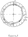
- FIG 4 an elevation view of waveband selection disc 100, shows that waveband selection disc 100 is the same as the rotating disc 24 of the preferred embodiment ( Figure 2), except for the absence of any variable scanning aperture slits.
- waveband selection slits 174, 176, 178 determine which waveband of light, i.e. blue, green, red will be transmitted to illumination spot 20.
- the color change marker 182 and clock speed holes 188 ensure proper synchronization with the analyzing drum.
- a second rotating disc 120 having variable scanning slits 152, 154, 156 is provided in the optical path of the image from the magnification optics 48.
- variable scanning aperture disc 120 is similar to the rotating disc 24 of the preferred embodiment ( Figure 2), except for the absence of any waveband selection slits.
- disc 120 includes color change marker 182 and clock speed holes 188 to ensure synchronization with the analyzing drum, and slits 152, 154, 156 respectively transmit the right hand image portion 60, central image portion 58 and left hand image portion 162 during successive analyzing drum revolutions as disc 120 rotates at one third the speed of the analyzing drum.
- light transmitted by disc 120 is focused by lens 180 onto photomultiplier 126 for detection.
- the combined effect of rotating discs 100, 120 is to select right, center and left image spot portions for separate waveband detection.
- the synchronized selection of different image portions for detection during each waveband pass compensates for the displacement in scanning head position during each revolution of the analyzing drum.
- the stagger compensation optical system advantageously provides an optical system and method for ensuring alignment of all waveband image point data by optically displacing the portion of the image detected during each waveband scan, i.e. each successive rotation of the analyzing drum, by a transverse distance equal to the transverse distance travelled by the optical scanning head during each rotation of the analyzing drum.
- this remarkable result is obtained in a light weight, compact structure that does not add appreciable weight, complexity or cost to the scanner.
Landscapes
- Engineering & Computer Science (AREA)
- Multimedia (AREA)
- Signal Processing (AREA)
- Facsimile Scanning Arrangements (AREA)
Claims (20)
- Lecteur optique, comprenant :
un tambour rotatif (12) d'analyse ayant une surface circonférentielle destinée à porter une oeuvre originale,
un dispositif (14) d'éclairement,
une optique (18) de lecture mobile transversalement à la direction de rotation du tambour (2) afin qu'elle dirige la lumière du dispositif d'éclairement (14) à la surface du tambour et délimite une surface d'image qui progresse transversalement à la direction de rotation du tambour (12),
un dispositif collecteur optique (36) placé dans la tête de lecture optique, mobile transversalement à la direction de rotation du tambour et destiné à collecter la lumière, modulée par l'oeuvre, provenant de la zone d'image,
un dispositif (24, 68) de dispersion spectrale destiné à disperser la lumière collectée par le dispositif collecteur optique en un spectre, et
un détecteur (26) destiné à recevoir et détecter la lumière du dispositif de dispersion spectrale,
caractérisé par
un dispositif à ouverture variant dans l'espace, comprenant un disque rotatif (24) ayant n fentes circonférentielles (52, 54, 56) d'ouverture couvrant chacune un arc d'environ 360/n° et ayant un rayon de courbure différent, disposées sur le trajet optique entre le dispositif collecteur optique (36) et le dispositif (24, 68) de dispersion spectrale, l'ouverture du dispositif à ouverture variant spatialement étant destinée à faire varier une ouverture en synchronisme avec la rotation du tambour (12) afin que la lumière de parties adjacentes de la zone d'image soit sélectionnée d'une manière telle que la lumière transmise par le dispositif (24, 68) de dispersion de couleurs pendant un nombre prédéterminé de rotations successives du tambour (12) a été modulée par la même région de l'oeuvre, n étant un nombre entier supérieur à 1. - Lecteur optique selon la revendication 1, comprenant en outre une ouverture fixe (22) placée sur le trajet optique près du dispositif à ouverture variant spatialement (52, 54, 56).
- Lecteur optique selon la revendication 1 ou 2, dans lequel, pendant le nombre prédéterminé de rotations du tambour (12), des données correspondant à ladite région de l'oeuvre sont détectées dans au moins trois bandes de longueurs d'onde.
- Lecteur optique selon la revendication 1, 2 ou 3, dans lequel lesdites parties de la zone de l'image sont décalées transversalement d'une distance correspondant à la distance transversale de déplacement de la tête de lecture optique pendant un tour du tambour (12).
- Lecteur optique selon la revendication 4, dans lequel lesdites parties de la zone de l'image se recouvrent.
- Lecteur optique selon l'une quelconque des revendications précédentes, dans lequel n est égal à 3.
- Lecteur optique selon la revendication 6, dans lequel le dispositif de dispersion spectrale comprend un prisme (68) de dispersion de couleurs destiné à recevoir la lumière des fentes (52, 54, 56) d'ouverture du disque (24), le prisme (68) de dispersion de lumière dispersant la lumière en un spectre ayant au moins trois bandes de longueurs d'onde.
- Lecteur optique selon la revendication 7, dans lequel la lumière dispersée dans le spectre provenant du prisme (68) de dispersion de couleurs tombe sur une région de sélection de bande de longueurs d'onde du disque (24), la région de sélection de bande de longueurs d'onde étant déplacée par rapport aux fentes (52, 54, 56) d'ouverture, la région de sélection de bande de longueurs d'onde ayant trois fentes circonférentielles partielles (74, 76, 78) de sélection de bande de longueurs d'onde, chacune des fentes (74, 76, 78) de sélection de bande de longueurs d'onde correspondant à environ 120° d'arc et ayant un rayon diffèrent.
- Lecteur optique selon la revendication 6, 7 ou 8, dans lequel le disque (24) est destiné à tourner en synchronisme avec le tambour (12) à un tiers de sa vitesse de rotation.
- Lecteur optique selon la revendication 8, dans lequel chacune des fentes (74, 76, 78) de sélection de bande de longueurs d'onde correspond à l'une des fentes (52, 54, 56) d'ouverture et reçoit la lumière dispersée du spectre correspondant à l'une des parties d'image disposée de manière que, pendant l'aimantation prédéterminée du tambour (12), le disque (24) effectue une rotation et le détecteur (26) reçoive et détecte successivement chaque bande de longueurs d'onde de la lumière modulée par ladite région de l'oeuvre.
- Lecteur optique selon l'une quelconque des revendications précédentes, comprenant en outre une optique (48) de grandissement placée sur le trajet optique de la lumière allant de la zone d'image au dispositif à ouverture variant spatialement, l'optique de grandissement (48) ajustant optiquement le déplacement transversal entre les parties d'image de la zone d'image.
- Lecteur optique comprenant :
un tambour rotatif (12) d'analyse ayant une surface circonférentielle destinée à porter une oeuvre originale,
un dispositif (14) d'éclairement,
une optique (18) de lecture mobile transversalement à la direction de rotation du tambour (12) et destinée à diriger la lumière du dispositif d'éclairement (18) à la surface du tambour pour la délimitation d'une zone d'image progressant transversalement à la direction de rotation du tambour (12),
un dispositif collecteur optique (36) placé dans la tête optique de lecture, mobile transversalement à la direction de rotation du tambour (12) et destiné à collecter la lumière modulée par l'oeuvre et provenant de la zone d'image, et
un détecteur (126) destiné à recevoir et détecter la lumière du dispositif collecteur optique (36),
caractérisé en ce que :
le dispositif d'éclairement (14) comprend un dispositif (100, 104) de sélection de bandes de longueurs d'onde destiné à transmettre séquentiellement des bandes distinctes de longueurs d'onde de la lumière d'éclairement à l'optique de lecture (18), et par
un dispositif à ouverture variant spatialement, comprenant un disque rotatif (120) ayant n fentes circonférentielles (152, 154, 156) d'ouverture recouvrant chacune un arc approximativement égal à 360/n° et ayant un rayon différent de courbure, disposé sur le trajet optique entre le dispositif collecteur optique (36) et le détecteur (126), le dispositif à ouverture variant spatialement étant destiné à faire varier l'ouverture en synchronisme avec la rotation du tambour (12) de manière que la lumière de parties adjacentes de la zone d'image soit sélectionnée d'une manière telle que la lumière transmise au détecteur (126) pendant un nombre prédéterminé de rotations successives du tambour a été modulée par la même région de l'oeuvre, n étant un nombre entier supérieur à 1. - Lecteur optique selon la revendication 12, dans lequel les parties de la zone d'image sont décalées transversalement par une distance correspondant à la distance transversale de déplacement de la tête optique de lecture (18) pendant un tour du tambour (12).
- Lecteur optique selon la revendication 12 ou 13, comportant en outre une optique de grandissement (48) placée sur le trajet optique entre le dispositif collecteur optique (36) et le dispositif à ouverture variant spatialement, l'optique de grandissement ajustant optiquement le déplacement transversal entre les parties de la zone d'image.
- Lecteur optique selon la revendication 12, 13 ou 14, dans lequel le dispositif (100, 104) de sélection de bande de longueurs d'onde transmet séquentiellement trois bandes de longueurs d'onde pendant trois tours successifs du tambour (12).
- Lecteur optique selon l'une quelconque des revendications 12 à 15, dans lequel n est égal à 3.
- Lecteur optique selon l'une quelconque des revendications 12 à 16, comprenant une ouverture fixe (22) disposée sur le trajet optique près du dispositif à ouverture variant spatialement.
- Lecteur optique selon la revendication 16, dans lequel le disque (120) est destiné à tourner en synchronisme avec le tambour (12) au tiers de sa vitesse de rotation.
- Procédé de lecture optique, comprenant les étapes suivantes :(a) l'éclairement d'une zone d'image à la surface d'un tambour rotatif (12) d'analyse, le tambour ayant une configuration et des dimensions telles qu'il peut porter une oeuvre originale,(b) la collecte de la lumière modulée par la partie de l'oeuvre contenue dans la zone d'image,(c) la dispersion de la lumière collectée en un spectre, et(d) la détection de la lumière dispersée,caractérisé par les étapes suivantes :(e) la transmission sélective de parties de lumière collectées, modulées par la même région de l'oeuvre pendant un nombre prédéterminé de rotations du tambour à l'aide d'un disque rotatif (24) ayant n fentes circonférentielles (52, 54, 56) d'ouverture recouvrant chacune un arc d'environ 360/n° et ayant un rayon de courbure différent, n étant un nombre entier supérieur à 1, avant l'étape (c), et(f) la sélection de différentes bandes de longueurs d'onde du spectre pendant des rotations successives du tambour et avant l'étape (d).
- Procédé de lecture optique, comprenant les étapes suivantes :(a) l'éclairement d'une zone d'image à la surface d'un tambour rotatif (12) d'analyse, cette surface ayant une configuration et des dimensions telles qu'elle peut porter une oeuvre originale,(b) la collecte de la lumière modulée par la partie de l'oeuvre se trouvant dans la zone d'image, et(c) la détection de la lumière collectée,caractérisé en ce que :
l'étape (a) comprend l'éclairement de la zone d'image à la surface du tambour rotatif d'analyse avec des bandes de longueurs d'onde distinctes de la lumière pendant des rotations successives du tambour d'analyse (10), et par
le passage sélectif d'une partie de la lumière collectée, à l'aide d'un disque rotatif (24) ayant n fentes circonférentielles (52, 54, 56) d'ouverture recouvrant chacune un arc d'environ 360/n° et ayant un rayon différent de courbure, n étant un nombre entier supérieur à 1, avant l'étape (c), d'une manière telle que la lumière transmise pendant les rotations successives d'un nombre prédéterminé de rotations du tambour (12) a été modulée par la même région de l'oeuvre.
Priority Applications (5)
| Application Number | Priority Date | Filing Date | Title |
|---|---|---|---|
| EP88307585A EP0355219B1 (fr) | 1988-08-16 | 1988-08-16 | Système optique pour la compensation du déplacement dans un dispositif de balayage optique |
| DE88307585T DE3888968D1 (de) | 1988-08-16 | 1988-08-16 | Optisches System für Versatzkompensation in einem optischen Abtaster. |
| US07/385,494 US5000570A (en) | 1985-08-16 | 1989-07-26 | Optical system for stagger compensation in an optical scanner |
| JP1209508A JPH02100051A (ja) | 1988-08-16 | 1989-08-11 | 光学スキャナーにおけるずれ補償のための光学系 |
| CA000608282A CA1313502C (fr) | 1988-08-16 | 1989-08-14 | Systeme optique pour corriger l'etagement dans un appareil a balayage optique |
Applications Claiming Priority (1)
| Application Number | Priority Date | Filing Date | Title |
|---|---|---|---|
| EP88307585A EP0355219B1 (fr) | 1988-08-16 | 1988-08-16 | Système optique pour la compensation du déplacement dans un dispositif de balayage optique |
Publications (2)
| Publication Number | Publication Date |
|---|---|
| EP0355219A1 EP0355219A1 (fr) | 1990-02-28 |
| EP0355219B1 true EP0355219B1 (fr) | 1994-04-06 |
Family
ID=8200179
Family Applications (1)
| Application Number | Title | Priority Date | Filing Date |
|---|---|---|---|
| EP88307585A Expired - Lifetime EP0355219B1 (fr) | 1985-08-16 | 1988-08-16 | Système optique pour la compensation du déplacement dans un dispositif de balayage optique |
Country Status (5)
| Country | Link |
|---|---|
| US (1) | US5000570A (fr) |
| EP (1) | EP0355219B1 (fr) |
| JP (1) | JPH02100051A (fr) |
| CA (1) | CA1313502C (fr) |
| DE (1) | DE3888968D1 (fr) |
Cited By (1)
| Publication number | Priority date | Publication date | Assignee | Title |
|---|---|---|---|---|
| CN101978247B (zh) * | 2008-03-20 | 2012-03-21 | 皇家飞利浦电子股份有限公司 | 光电检测器和测量光的方法 |
Families Citing this family (10)
| Publication number | Priority date | Publication date | Assignee | Title |
|---|---|---|---|---|
| EP0477446A1 (fr) * | 1990-09-27 | 1992-04-01 | Itek Colour Graphics Limited | Système optique amélioré pour la compensation du déplacement dans un dispositif de balayage optique |
| US5380999A (en) * | 1993-12-29 | 1995-01-10 | International Business Machines, Corp. | Linear scanning using a single illumination and imaging optic stations with a first pair of parallel mirrors and a second pair of mirrors extending into paths of light beams |
| US5872591A (en) * | 1996-02-21 | 1999-02-16 | Pakon, Inc. | Film scanner |
| US6882359B1 (en) | 2000-03-28 | 2005-04-19 | Eastman Kodak Company | Film scanner |
| US6636305B2 (en) | 2001-09-13 | 2003-10-21 | New Chromex, Inc. | Apparatus and method for producing a substantially straight instrument image |
| US20040207924A1 (en) * | 2003-01-10 | 2004-10-21 | Xhp Microsystems, Inc. | Prism color separation (PCS) system for display applications |
| US7400430B2 (en) * | 2003-09-25 | 2008-07-15 | Infoprint Solutions Company, Llc. | Detecting and compensating for color misregistration produced by a color scanner |
| JP5320329B2 (ja) * | 2010-03-15 | 2013-10-23 | 株式会社日立ハイテクノロジーズ | Sem式欠陥観察装置および欠陥画像取得方法 |
| WO2012145741A2 (fr) * | 2011-04-22 | 2012-10-26 | The University Of Memphis Reasearch Foundation | Disques sélectifs du point de vue spatial, dispositifs de réalisation d'image sous-millimétrique, procédés de dispositifs de balayage de profilage de réalisation d'image sous-millimétrique, dispositifs de spectrométrie et procédés de spectrométrie |
| JP7180707B2 (ja) * | 2021-03-15 | 2022-11-30 | 横河電機株式会社 | 共焦点スキャナ及び共焦点顕微鏡 |
Family Cites Families (4)
| Publication number | Priority date | Publication date | Assignee | Title |
|---|---|---|---|---|
| GB1600005A (en) * | 1977-03-14 | 1981-10-14 | Linotype Paul Ltd | Electro-optical scanning |
| US4415925A (en) * | 1981-02-05 | 1983-11-15 | Canon Kabushiki Kaisha | Color original readout apparatus |
| DE3412723A1 (de) * | 1984-04-04 | 1985-10-17 | Fogra Deutsche Forschungsgesellschaft für Druck- und Reproduktionstechnik e.V., 8000 München | Verfahren zur einstellung eines scanners auf eine reproduktionsvorlage |
| JPS63301688A (ja) * | 1987-05-30 | 1988-12-08 | Victor Co Of Japan Ltd | フィ−ルド順次カラ−テレビジョンカメラ |
-
1988
- 1988-08-16 EP EP88307585A patent/EP0355219B1/fr not_active Expired - Lifetime
- 1988-08-16 DE DE88307585T patent/DE3888968D1/de not_active Expired - Lifetime
-
1989
- 1989-07-26 US US07/385,494 patent/US5000570A/en not_active Expired - Fee Related
- 1989-08-11 JP JP1209508A patent/JPH02100051A/ja active Pending
- 1989-08-14 CA CA000608282A patent/CA1313502C/fr not_active Expired - Fee Related
Cited By (1)
| Publication number | Priority date | Publication date | Assignee | Title |
|---|---|---|---|---|
| CN101978247B (zh) * | 2008-03-20 | 2012-03-21 | 皇家飞利浦电子股份有限公司 | 光电检测器和测量光的方法 |
Also Published As
| Publication number | Publication date |
|---|---|
| JPH02100051A (ja) | 1990-04-12 |
| CA1313502C (fr) | 1993-02-09 |
| DE3888968D1 (de) | 1994-05-11 |
| US5000570A (en) | 1991-03-19 |
| EP0355219A1 (fr) | 1990-02-28 |
Similar Documents
| Publication | Publication Date | Title |
|---|---|---|
| EP0539691B1 (fr) | Disque de Nipkow pour dispositif à balayage optique confocal | |
| EP0355219B1 (fr) | Système optique pour la compensation du déplacement dans un dispositif de balayage optique | |
| US8143565B2 (en) | Adjustable multimode lightfield imaging system having an actuator for changing position of a non-homogeneous filter module relative to an image-forming optical module | |
| AU731476C (en) | Multi-spectral two-dimensional imaging spectrometer | |
| JPH06189073A (ja) | 光学スキャナー | |
| JPH01237619A (ja) | 光学装置 | |
| US3922092A (en) | Monochromator and light dispersing apparatus | |
| CA2026350C (fr) | Methode de commande d'exposition et appareil de photoreprographie couleur | |
| US4368974A (en) | Illuminating system for producing prints on variable contrast photosensitive material, filter strip for said system and lamphouse comprising the same | |
| EP0655129B1 (fr) | Spectrometre ayant un filtre flexible rotatif | |
| EP0477446A1 (fr) | Système optique amélioré pour la compensation du déplacement dans un dispositif de balayage optique | |
| US4628350A (en) | Image enhancement | |
| US4620235A (en) | Disc film scanning apparatus | |
| US4216495A (en) | Electro-optical scanning | |
| EP1549991A1 (fr) | Appareil et procede de discrimination spectrale | |
| US5262832A (en) | Color separation optical system for use in color copying machine | |
| JPS648806B2 (fr) | ||
| US3945731A (en) | Color control system for optical image apparatus | |
| JPH0398378A (ja) | 光電スキャナ | |
| GB1600005A (en) | Electro-optical scanning | |
| JPH0686017A (ja) | カラー画像読取装置 | |
| NO812403L (no) | Anordning for optisk kompensasjon i filmfremvisningsapparat | |
| JPS5922228B2 (ja) | カラ−電子写真の露光方法 | |
| JPS6014565A (ja) | カラ−原稿読取装置 | |
| JPH0124306B2 (fr) |
Legal Events
| Date | Code | Title | Description |
|---|---|---|---|
| PUAI | Public reference made under article 153(3) epc to a published international application that has entered the european phase |
Free format text: ORIGINAL CODE: 0009012 |
|
| AK | Designated contracting states |
Kind code of ref document: A1 Designated state(s): DE FR GB |
|
| 17P | Request for examination filed |
Effective date: 19900504 |
|
| 17Q | First examination report despatched |
Effective date: 19920316 |
|
| GRAA | (expected) grant |
Free format text: ORIGINAL CODE: 0009210 |
|
| AK | Designated contracting states |
Kind code of ref document: B1 Designated state(s): DE FR GB |
|
| PG25 | Lapsed in a contracting state [announced via postgrant information from national office to epo] |
Ref country code: FR Effective date: 19940406 Ref country code: DE Effective date: 19940406 |
|
| REF | Corresponds to: |
Ref document number: 3888968 Country of ref document: DE Date of ref document: 19940511 |
|
| EN | Fr: translation not filed | ||
| PLBE | No opposition filed within time limit |
Free format text: ORIGINAL CODE: 0009261 |
|
| STAA | Information on the status of an ep patent application or granted ep patent |
Free format text: STATUS: NO OPPOSITION FILED WITHIN TIME LIMIT |
|
| 26N | No opposition filed | ||
| REG | Reference to a national code |
Ref country code: GB Ref legal event code: 732E |
|
| REG | Reference to a national code |
Ref country code: GB Ref legal event code: IF02 |
|
| REG | Reference to a national code |
Ref country code: GB Ref legal event code: 732E |
|
| PGFP | Annual fee paid to national office [announced via postgrant information from national office to epo] |
Ref country code: GB Payment date: 20020905 Year of fee payment: 15 |
|
| PG25 | Lapsed in a contracting state [announced via postgrant information from national office to epo] |
Ref country code: GB Free format text: LAPSE BECAUSE OF NON-PAYMENT OF DUE FEES Effective date: 20030816 |
|
| GBPC | Gb: european patent ceased through non-payment of renewal fee |
Effective date: 20030816 |