EP0355302A2 - Luftauslass - Google Patents
Luftauslass Download PDFInfo
- Publication number
- EP0355302A2 EP0355302A2 EP89111090A EP89111090A EP0355302A2 EP 0355302 A2 EP0355302 A2 EP 0355302A2 EP 89111090 A EP89111090 A EP 89111090A EP 89111090 A EP89111090 A EP 89111090A EP 0355302 A2 EP0355302 A2 EP 0355302A2
- Authority
- EP
- European Patent Office
- Prior art keywords
- housing section
- air outlet
- pin
- cover
- section
- Prior art date
- Legal status (The legal status is an assumption and is not a legal conclusion. Google has not performed a legal analysis and makes no representation as to the accuracy of the status listed.)
- Granted
Links
Images

Classifications
-
- F—MECHANICAL ENGINEERING; LIGHTING; HEATING; WEAPONS; BLASTING
- F24—HEATING; RANGES; VENTILATING
- F24F—AIR-CONDITIONING; AIR-HUMIDIFICATION; VENTILATION; USE OF AIR CURRENTS FOR SCREENING
- F24F13/00—Details common to, or for air-conditioning, air-humidification, ventilation or use of air currents for screening
- F24F13/02—Ducting arrangements
- F24F13/06—Outlets for directing or distributing air into rooms or spaces, e.g. ceiling air diffuser
Definitions
- the invention relates to an air outlet from a housing with a lower and an upper, each cylindrical housing section.
- the lower housing section is provided with an inflow opening
- the upper housing section which is larger in diameter, is provided with outlet flow openings arranged in a uniform distribution over the edge region of a cover.
- Such an air outlet which is particularly suitable for installation in a cavity floor, is known, for example, from DE-OS 34 17 002.
- This air outlet has a cylindrical upper housing section, referred to as an air distribution head, below which a lower housing section, referred to as an air inlet pot, is rotatably arranged.
- a radial connecting piece for connecting an air hose protrudes from the air inlet pot. This makes it possible to always bring the air hose in the floor cavity straight to the air outlet, regardless of the arrangement of feet.
- the known air outlet has a height-adjustable perforated disc, which serves to change the flow resistance of the air outlet, the change being brought about by rotating the cover.
- the invention has for its object to provide an air outlet of the type described in such a way that it can be effectively closed and opened in a simple manner without disassembly and reassembly.
- an overflow cross section from the lower housing section to the upper housing section can be shut off or released in the simplest manner.
- the closure disk is seated on a pin with its free end pointing downward, which is guided in a sleeve extending from the bottom of the lower housing section, a cylindrical spring being arranged around the pin, with which the disk is directed towards the underside of the Lid is pressable.
- the closure disk can be held at a distance above the overflow cross section connecting the housing sections, as a result of which the air outlet is activated.
- a sleeve sits concentrically in the cover, through which the actuating pin can be inserted, by means of which the locking disk can be displaced and locked and unlocked from the top against the action of the cylinder spring, and thus can be displaced from the bottom to the top.
- the closure disk can optionally be transferred from its upper position, which releases the air outlet, to its lower position, which blocks the air outlet.
- an embodiment of the invention provides that the disk can be fixed in its lower shut-off position by a grid locking of the pin which is known per se.
- Such grid locks are used, for example, in ballpoint pens, the ballpoint pen refill being axially displaceable between two end positions and being alternately fixable in one or the other position by a simple push-button operation.
- the air outlet consists essentially of a lower housing section 1 and an upper housing section 2, which are arranged coaxially to one another, the upper housing section 2 being larger in diameter than the lower housing section 1.
- the lower housing section 1 is provided with an inflow opening, not shown, through which supply air can flow in from a floor cavity into the air outlet.
- the upper housing section 2 is closed by a cover 3, in the edge region of which slot-shaped outlet openings 4 are arranged in a uniform distribution.
- the lower housing section 1 is provided with a concentric sleeve 6 starting from a web 5, in which a pin 7 is guided, which is on the sleeve 6 thereof Pioneering end carries a closure disc 8, which can be shifted from the extended position in FIG. 2 to the position shown in broken lines by means of a coil spring 9 arranged around the pin 7.
- a sleeve 10 is provided concentrically, through the opening of which an actuating pin (not shown) can be inserted, the shape of which, moreover, no requirements are imposed. If the actuating pin inserted through the sleeve 10 exerts pressure on a raster pin 11 projecting above the locking disk 8 and stored in the pin 7, the locking of the pin 9 is released and the locking disk 8 with the pin 9 is drawn from the drawn into the dot-dash line transferred position shown, whereby the overflow cross section between the lower housing section 1 and the upper housing section 2 is released. By renewed pressure loading of the raster pin 11, the closure disk 8 can be transferred just as easily from the dash-dotted line to the extended position in FIG. 2, so that the overflow cross section between the two housing sections 1 and 2 is blocked and the air outlet thus remains inactive until a renewed displacement of the closure disk 8 is brought about.
Landscapes
- Engineering & Computer Science (AREA)
- Chemical & Material Sciences (AREA)
- Combustion & Propulsion (AREA)
- Mechanical Engineering (AREA)
- General Engineering & Computer Science (AREA)
- Air-Flow Control Members (AREA)
- Ventilation (AREA)
- Self-Closing Valves And Venting Or Aerating Valves (AREA)
- Catching Or Destruction (AREA)
- Respiratory Apparatuses And Protective Means (AREA)
Abstract
Description
- Die Erfindung betrifft einen Luftauslaß aus einem Gehäuse mit einem unteren und einem oberen, jeweils zylinderförmigen Gehäuseabschnitt. Der untere Gehäuseabschnitt ist mit einer Einströmöffnung versehen, wogegen der obere, im Durchmesser größere Gehäuseabschnitt mit über den Randbereich eines Deckels in gleichmäßiger Verteilung angeordneten Auslaßströmöffnungen versehen ist.
- Ein derartiger, insbesondere für den Einbau in einen Hohlraumboden geeigneter Luftauslaß ist beispielsweise aus der DE-OS 34 17 002 bekannt. Dieser Luftauslaß weist einen zylindrischen oberen, als Luftverteilkopf bezeichneten Gehäuseabschnitt auf, unter dem exzentrisch ein als Lufteinlaßtopf bezeichneter unterer Gehäuseabschnitt drehbar angeordnet ist. Von dem Lufteinlaßtopf steht ein radialer Anschlußstutzen zum Anschließen eines Luftschlauches ab. Damit ist es möglich, den Luftschlauch im Bodenhohlraum unabhängig von der Anordnung von Füßen stets geradlinig an den Luftauslaß heranzuführen. Weiterhin weist der bekannte Luftauslaß eine höhenverstellbare Lochscheibe auf, die zur Veränderung des Strömungswiderstandes des Luftauslasses dient, wobei die Veränderung durch eine Drehung des Deckels herbeigeführt wird.
- In der Praxis ergibt sich häufig die Notwendigkeit, die Anzahl der gleichmäßig über beispielsweise eine Bodenfläche verteilten aktiven Luftauslässe je nach Nutzung des betreffenden Raumes zu verändern. Dazu werden bestimmte Luftauslässe verschlossen, wozu es erforderlich ist, die betreffenden Auslässe teilweise zu demontieren, um darin ein Verschlußstück einzubauen.
- Der Erfindung liegt die Aufgabe zugrunde, einen Luftauslaß der eingangs beschriebenen Art so auszubilden, daß er sich ohne De- und Remontage in einfacher Weise wirksam verschließen und öffnen läßt.
- Zur Lösung dieser Aufgabe wird von einem Luftauslaß der im Oberbegriff des Anspruchs 1 genannten gattungsgemäßen Art ausgegangen, welcher erfindungsgemäß die im kennzeichnenden Teil desselben angegebenen Merkmale aufweist.
- Durch die erfindungsgemäße Verschlußscheibe läßt sich in Abhängigkeit von deren Niveau ein Überströmquerschnitt vom unteren Gehäuseabschnitt zum oberen Gehäuseabschnitt in einfachster Weise absperren bzw. freigeben.
- Nach einer Ausgestaltung der Erfindung sitzt die Verschlußscheibe auf einem mit seinem freien Ende nach unten weisenden Zapfen, der in einer vom Boden des unteren Gehäuseabschnitts ausgehenden Hülse geführt ist, wobei um den Zapfen eine Zylinderfeder angeordnet ist, mit der die Scheibe in Richtung zur Unterseite des Deckels preßbar ist.
- Mit Hilfe der Zylinderfeder läßt sich die Verschlußscheibe in einem Abstand über dem die Gehäuseabschnitte verbindenden Überströmquerschnitt halten, wodurch der Luftauslaß aktiviert ist.
- Nach einer weiteren Ausgestaltung der Erfindung sitzt konzentrisch im Deckel eine Muffe, durch die der Betätigungsstift einführbar ist, mit dem die Verschlußscheibe gegen die Wirkung der Zylinderfeder sowohl von oben nach unten verlagerbar und verriegelbar wie auch entriegelbar und dadurch von unten nach oben verlagerbar ist.
- Durch diese Ausgestaltung kann die Verschlußscheibe wahlweise aus ihrer oberen, den Luftauslaß freigebenden Position in ihre untere, den Luftauslaß absperrende Position überführt werden.
- Schließlich sieht eine Ausgestaltung der Erfindung noch vor, daß die Scheibe in ihrer unteren Absperrposition durch eine an sich bekannte Rasterverriegelung des Zapfens fixierbar ist.
- Derartige Rasterverriegelungen finden beispielsweise bei Kugelschreibern Verwendung, wobei die Kugelschreibermine zwischen zwei Endpositionen axial verschiebbar gelagert ist und durch eine einfache Druckknopfbetätigung wechselweise in der einen oder anderen Position fixierbar ist.
- In der Zeichnung ist ein Ausführungsbeispiel eines erfindungsgemäßen Luftauslasses dargestellt. Es zeigen:
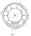
- Fig. 1 den Luftauslaß im Grundriß und
- Fig. 2 den Luftauslaß in einem Schnitt nach der Linie II - II der Fig. 1.
- Der Luftauslaß besteht im wesentlichen aus einem unteren Gehäuseabschnitt 1 und einem oberen Gehäuseabschnitt 2, die koaxial zueinander angeordnet sind, wobei der obere Gehäuseabschnitt 2 gegenüber dem unteren Gehäuseabschnitt 1 im Durchmesser größer ausgebildet ist.
- Der untere Gehäuseabschnitt 1 ist mit einer nicht dargestellten Einströmöffnung versehen, über die Zuluft aus einem Bodenhohlraum in den Luftauslaß einströmen kann.
- Der obere Gehäuseabschnitt 2 ist durch einen Deckel 3 verschlossen, in dessen Randbereich schlitzförmige Austrittsöffnungen 4 in gleichmäßiger Verteilung angeordnet sind.
- Wie insbesondere Fig. 2 zeigt, ist der untere Gehäuseabschnitt 1 mit einer von einem Steg 5 ausgehenden konzentrischen Hülse 6 versehen, worin ein Zapfen 7 geführt ist, der an seinem von der Hülse 6 wegweisenden Ende eine Verschlußscheibe 8 trägt, die mit Hilfe einer um den Zapfen 7 angeordneten Schraubenfeder 9 aus der in Fig. 2 ausgezogenen Position in die strichpunktiert dargestellte Position verlagerbar ist.
- Im Deckel 3 des oberen Gehäuseabschnitts 2 ist konzentrisch eine Muffe 10 vorgesehen, durch deren Öffnung sich ein nicht dargestellter Betätigungsstift einführen läßt, an dessen Formgebung im übrigen keine Anforderungen gestellt werden. Wird über den durch die Muffe 10 eingeführten Betätigungsstift ein Druck auf einen über die Verschlußscheibe 8 vorstehenden und in dem Zapfen 7 gelagerten Rasterstift 11 ausgeübt, so wird die Verriegelung des Zapfens 9 aufgehoben und mit dem Zapfen 9 die Verschlußscheibe 8 aus der ausgezogenen in die strichpunktiert dargestellte Position überführt, wodurch der Überströmquerschnitt zwischen dem unteren Gehäuseabschnitt 1 und dem oberen Gehäuseabschnitt 2 freigegeben wird. Durch eine erneute Druckbelastung des Rasterstiftes 11 läßt sich ebenso einfach die Verschlußscheibe 8 aus der strichpunktierten in die ausgezogene Position der Fig. 2 überführen, so daß der Überströmquerschnitt zwischen den beiden Gehäuseabschnitten 1 und 2 versperrt ist und damit der Luftauslaß so lange inaktiv bleibt, bis eine erneute Verlagerung der Verschlußscheibe 8 herbeigeführt wird.
Claims (4)
Priority Applications (1)
| Application Number | Priority Date | Filing Date | Title |
|---|---|---|---|
| AT89111090T ATE100566T1 (de) | 1988-08-22 | 1989-06-19 | Luftauslass. |
Applications Claiming Priority (2)
| Application Number | Priority Date | Filing Date | Title |
|---|---|---|---|
| DE8810620U | 1988-08-22 | ||
| DE8810620U DE8810620U1 (de) | 1988-08-22 | 1988-08-22 | Luftauslaß |
Publications (3)
| Publication Number | Publication Date |
|---|---|
| EP0355302A2 true EP0355302A2 (de) | 1990-02-28 |
| EP0355302A3 EP0355302A3 (de) | 1991-10-16 |
| EP0355302B1 EP0355302B1 (de) | 1994-01-19 |
Family
ID=6827142
Family Applications (1)
| Application Number | Title | Priority Date | Filing Date |
|---|---|---|---|
| EP89111090A Expired - Lifetime EP0355302B1 (de) | 1988-08-22 | 1989-06-19 | Luftauslass |
Country Status (5)
| Country | Link |
|---|---|
| EP (1) | EP0355302B1 (de) |
| JP (1) | JPH02101348A (de) |
| AT (1) | ATE100566T1 (de) |
| DE (2) | DE8810620U1 (de) |
| ES (1) | ES2048789T3 (de) |
Cited By (1)
| Publication number | Priority date | Publication date | Assignee | Title |
|---|---|---|---|---|
| US6544117B1 (en) * | 2002-01-03 | 2003-04-08 | Gebruder Trox Gmbh | Motorized floor diffuser system |
Families Citing this family (3)
| Publication number | Priority date | Publication date | Assignee | Title |
|---|---|---|---|---|
| DE3928621C2 (de) * | 1989-08-30 | 1995-03-30 | Krantz Tkt Gmbh | Bodenquellauslaß |
| DE9407055U1 (de) * | 1994-04-28 | 1994-08-04 | H. Krantz-Tkt Gmbh, 51465 Bergisch Gladbach | Bodenquellauslaß aus einem zylindrischen Gehäuse |
| NL2021244B1 (en) * | 2018-07-04 | 2020-01-15 | Tafkah B V | Ceiling vent |
Family Cites Families (4)
| Publication number | Priority date | Publication date | Assignee | Title |
|---|---|---|---|---|
| FR939973A (fr) * | 1947-01-27 | 1948-11-30 | Perfectionnements aux dispositifs de ventilation | |
| US2712786A (en) * | 1952-01-11 | 1955-07-12 | Peter A Argentieri | Flexible damper construction for diffusers and the like |
| DE3417002C2 (de) * | 1984-05-09 | 1993-11-18 | Schmidt Reuter | Luftauslaß für Hohlraumböden |
| US4749000A (en) * | 1987-10-19 | 1988-06-07 | American Standard Inc. | Normally open pneumatic air valve |
-
1988
- 1988-08-22 DE DE8810620U patent/DE8810620U1/de not_active Expired
-
1989
- 1989-06-19 AT AT89111090T patent/ATE100566T1/de not_active IP Right Cessation
- 1989-06-19 DE DE89111090T patent/DE58906743D1/de not_active Expired - Fee Related
- 1989-06-19 EP EP89111090A patent/EP0355302B1/de not_active Expired - Lifetime
- 1989-06-19 ES ES89111090T patent/ES2048789T3/es not_active Expired - Lifetime
- 1989-08-17 JP JP1210799A patent/JPH02101348A/ja active Pending
Cited By (1)
| Publication number | Priority date | Publication date | Assignee | Title |
|---|---|---|---|---|
| US6544117B1 (en) * | 2002-01-03 | 2003-04-08 | Gebruder Trox Gmbh | Motorized floor diffuser system |
Also Published As
| Publication number | Publication date |
|---|---|
| JPH02101348A (ja) | 1990-04-13 |
| ES2048789T3 (es) | 1994-04-01 |
| ATE100566T1 (de) | 1994-02-15 |
| EP0355302B1 (de) | 1994-01-19 |
| EP0355302A3 (de) | 1991-10-16 |
| DE58906743D1 (de) | 1994-03-03 |
| DE8810620U1 (de) | 1988-12-01 |
Similar Documents
| Publication | Publication Date | Title |
|---|---|---|
| DE3727843C2 (de) | Vorrichtung zum Erzeugen von Flüssigkeitsstrahlen | |
| DE1811817C3 (de) | Verdampfungsvorrichtung für ein flüchtiges Narkosemittel | |
| DE19849742A1 (de) | Ventil des Membrantyps | |
| CH617759A5 (de) | ||
| EP0665321A1 (de) | Wassereinleitvorrichtung für Dampfbügeleisen | |
| EP0679844B1 (de) | Bodenquellauslass aus einem zylindrischen Gehäuse | |
| DE3910135A1 (de) | Spuelventil | |
| DE102021001668A1 (de) | Filterpatrone und Wasserfiltervorrichtung | |
| EP0018438B1 (de) | Sanitäres Wasserventil | |
| EP0120988B1 (de) | Rückspülbares Filtergerät | |
| EP0355302A2 (de) | Luftauslass | |
| DE3430444A1 (de) | Kraftstoff-einspritzduese fuer eine brennkraftmaschine | |
| DE69402655T2 (de) | Abgabevorrichtung insbesondere für Farben und Lacke | |
| DE2606042C3 (de) | Als Regelventil arbeitender Steuerschieber | |
| DE2819065C2 (de) | Einhebel-Mischarmatur | |
| DE8811822U1 (de) | Vorrichtung zur wahlweisen Durchführung von Wasserpunktur oder Hydro-Ionisation | |
| DE2722889A1 (de) | Selbstschlussventil | |
| DE2727724C2 (de) | Füllrohrloses Füllorgan für Gegendruckfüllmaschinen | |
| EP2405061A2 (de) | Ventilvorrichtung | |
| DE2712444A1 (de) | Wirbelkammerventil | |
| EP0702741A1 (de) | Vorrichtung zum auslösen und unterbrechen des wasserlaufs aus einer wasseraustrittsöffnung | |
| DD146314A1 (de) | Dampfbuegeleisen | |
| DE4412825A1 (de) | Dampfbügeleisen | |
| DE8903436U1 (de) | Mit einem Sicherheitsventil ausgerüstete Sprühpistole | |
| DE4443292A1 (de) | Verteilereinrichtung für ein Fluid in einem Behälter |
Legal Events
| Date | Code | Title | Description |
|---|---|---|---|
| PUAI | Public reference made under article 153(3) epc to a published international application that has entered the european phase |
Free format text: ORIGINAL CODE: 0009012 |
|
| AK | Designated contracting states |
Kind code of ref document: A2 Designated state(s): AT BE CH DE ES FR GB GR IT LI LU NL SE |
|
| RIN1 | Information on inventor provided before grant (corrected) |
Inventor name: NISSEN, GERD Inventor name: GRUETERICH, MANFRED, DIPL.-ING. |
|
| 17P | Request for examination filed |
Effective date: 19901231 |
|
| PUAL | Search report despatched |
Free format text: ORIGINAL CODE: 0009013 |
|
| AK | Designated contracting states |
Kind code of ref document: A3 Designated state(s): AT BE CH DE ES FR GB GR IT LI LU NL SE |
|
| 17Q | First examination report despatched |
Effective date: 19920323 |
|
| GRAA | (expected) grant |
Free format text: ORIGINAL CODE: 0009210 |
|
| AK | Designated contracting states |
Kind code of ref document: B1 Designated state(s): AT BE CH DE ES FR GB GR IT LI LU NL SE |
|
| REF | Corresponds to: |
Ref document number: 100566 Country of ref document: AT Date of ref document: 19940215 Kind code of ref document: T |
|
| REF | Corresponds to: |
Ref document number: 58906743 Country of ref document: DE Date of ref document: 19940303 |
|
| ET | Fr: translation filed | ||
| GBT | Gb: translation of ep patent filed (gb section 77(6)(a)/1977) |
Effective date: 19940217 |
|
| REG | Reference to a national code |
Ref country code: GR Ref legal event code: FG4A Free format text: 3010509 |
|
| REG | Reference to a national code |
Ref country code: ES Ref legal event code: FG2A Ref document number: 2048789 Country of ref document: ES Kind code of ref document: T3 |
|
| ITF | It: translation for a ep patent filed | ||
| PGFP | Annual fee paid to national office [announced via postgrant information from national office to epo] |
Ref country code: LU Payment date: 19940531 Year of fee payment: 6 |
|
| EPTA | Lu: last paid annual fee | ||
| PLBE | No opposition filed within time limit |
Free format text: ORIGINAL CODE: 0009261 |
|
| STAA | Information on the status of an ep patent application or granted ep patent |
Free format text: STATUS: NO OPPOSITION FILED WITHIN TIME LIMIT |
|
| 26N | No opposition filed | ||
| EAL | Se: european patent in force in sweden |
Ref document number: 89111090.0 |
|
| PGFP | Annual fee paid to national office [announced via postgrant information from national office to epo] |
Ref country code: GR Payment date: 19950518 Year of fee payment: 7 |
|
| PGFP | Annual fee paid to national office [announced via postgrant information from national office to epo] |
Ref country code: SE Payment date: 19950606 Year of fee payment: 7 |
|
| PG25 | Lapsed in a contracting state [announced via postgrant information from national office to epo] |
Ref country code: LU Free format text: LAPSE BECAUSE OF NON-PAYMENT OF DUE FEES Effective date: 19950619 |
|
| PG25 | Lapsed in a contracting state [announced via postgrant information from national office to epo] |
Ref country code: SE Effective date: 19960620 |
|
| PG25 | Lapsed in a contracting state [announced via postgrant information from national office to epo] |
Ref country code: GR Free format text: THE PATENT HAS BEEN ANNULLED BY A DECISION OF A NATIONAL AUTHORITY Effective date: 19961231 |
|
| REG | Reference to a national code |
Ref country code: GR Ref legal event code: MM2A Free format text: 3010509 |
|
| EUG | Se: european patent has lapsed |
Ref document number: 89111090.0 |
|
| PGFP | Annual fee paid to national office [announced via postgrant information from national office to epo] |
Ref country code: AT Payment date: 19970613 Year of fee payment: 9 |
|
| PGFP | Annual fee paid to national office [announced via postgrant information from national office to epo] |
Ref country code: NL Payment date: 19970630 Year of fee payment: 9 |
|
| PG25 | Lapsed in a contracting state [announced via postgrant information from national office to epo] |
Ref country code: AT Free format text: LAPSE BECAUSE OF NON-PAYMENT OF DUE FEES Effective date: 19980619 |
|
| PG25 | Lapsed in a contracting state [announced via postgrant information from national office to epo] |
Ref country code: NL Free format text: LAPSE BECAUSE OF NON-PAYMENT OF DUE FEES Effective date: 19990101 |
|
| NLV4 | Nl: lapsed or anulled due to non-payment of the annual fee |
Effective date: 19990101 |
|
| PGFP | Annual fee paid to national office [announced via postgrant information from national office to epo] |
Ref country code: FR Payment date: 19990330 Year of fee payment: 11 |
|
| PGFP | Annual fee paid to national office [announced via postgrant information from national office to epo] |
Ref country code: ES Payment date: 19990603 Year of fee payment: 11 |
|
| PGFP | Annual fee paid to national office [announced via postgrant information from national office to epo] |
Ref country code: BE Payment date: 19990623 Year of fee payment: 11 |
|
| PGFP | Annual fee paid to national office [announced via postgrant information from national office to epo] |
Ref country code: DE Payment date: 20000607 Year of fee payment: 12 |
|
| PGFP | Annual fee paid to national office [announced via postgrant information from national office to epo] |
Ref country code: GB Payment date: 20000609 Year of fee payment: 12 |
|
| PG25 | Lapsed in a contracting state [announced via postgrant information from national office to epo] |
Ref country code: ES Free format text: THE PATENT HAS BEEN ANNULLED BY A DECISION OF A NATIONAL AUTHORITY Effective date: 20000620 |
|
| PGFP | Annual fee paid to national office [announced via postgrant information from national office to epo] |
Ref country code: CH Payment date: 20000626 Year of fee payment: 12 |
|
| PG25 | Lapsed in a contracting state [announced via postgrant information from national office to epo] |
Ref country code: BE Free format text: LAPSE BECAUSE OF NON-PAYMENT OF DUE FEES Effective date: 20000630 |
|
| BERE | Be: lapsed |
Owner name: H. KRANTZ G.M.B.H. & CO. Effective date: 20000630 |
|
| PG25 | Lapsed in a contracting state [announced via postgrant information from national office to epo] |
Ref country code: FR Free format text: LAPSE BECAUSE OF NON-PAYMENT OF DUE FEES Effective date: 20010228 |
|
| REG | Reference to a national code |
Ref country code: FR Ref legal event code: ST |
|
| PG25 | Lapsed in a contracting state [announced via postgrant information from national office to epo] |
Ref country code: GB Free format text: LAPSE BECAUSE OF NON-PAYMENT OF DUE FEES Effective date: 20010619 |
|
| PG25 | Lapsed in a contracting state [announced via postgrant information from national office to epo] |
Ref country code: LI Free format text: LAPSE BECAUSE OF NON-PAYMENT OF DUE FEES Effective date: 20010630 Ref country code: CH Free format text: LAPSE BECAUSE OF NON-PAYMENT OF DUE FEES Effective date: 20010630 |
|
| GBPC | Gb: european patent ceased through non-payment of renewal fee |
Effective date: 20010619 |
|
| REG | Reference to a national code |
Ref country code: CH Ref legal event code: PL |
|
| REG | Reference to a national code |
Ref country code: ES Ref legal event code: FD2A Effective date: 20020204 |
|
| PG25 | Lapsed in a contracting state [announced via postgrant information from national office to epo] |
Ref country code: DE Free format text: LAPSE BECAUSE OF NON-PAYMENT OF DUE FEES Effective date: 20020403 |
|
| PG25 | Lapsed in a contracting state [announced via postgrant information from national office to epo] |
Ref country code: IT Free format text: LAPSE BECAUSE OF NON-PAYMENT OF DUE FEES Effective date: 20050619 |