EP0355456A2 - Dispositif pour le traitement du sang avec un gaz - Google Patents
Dispositif pour le traitement du sang avec un gaz Download PDFInfo
- Publication number
- EP0355456A2 EP0355456A2 EP89113830A EP89113830A EP0355456A2 EP 0355456 A2 EP0355456 A2 EP 0355456A2 EP 89113830 A EP89113830 A EP 89113830A EP 89113830 A EP89113830 A EP 89113830A EP 0355456 A2 EP0355456 A2 EP 0355456A2
- Authority
- EP
- European Patent Office
- Prior art keywords
- blood
- gas
- connection
- container body
- gassing
- Prior art date
- Legal status (The legal status is an assumption and is not a legal conclusion. Google has not performed a legal analysis and makes no representation as to the accuracy of the status listed.)
- Granted
Links
Images

Classifications
-
- A—HUMAN NECESSITIES
- A61—MEDICAL OR VETERINARY SCIENCE; HYGIENE
- A61M—DEVICES FOR INTRODUCING MEDIA INTO, OR ONTO, THE BODY; DEVICES FOR TRANSDUCING BODY MEDIA OR FOR TAKING MEDIA FROM THE BODY; DEVICES FOR PRODUCING OR ENDING SLEEP OR STUPOR
- A61M1/00—Suction or pumping devices for medical purposes; Devices for carrying-off, for treatment of, or for carrying-over, body-liquids; Drainage systems
- A61M1/14—Dialysis systems; Artificial kidneys; Blood oxygenators ; Reciprocating systems for treatment of body fluids, e.g. single needle systems for hemofiltration or pheresis
- A61M1/32—Oxygenators without membranes
-
- A—HUMAN NECESSITIES
- A61—MEDICAL OR VETERINARY SCIENCE; HYGIENE
- A61M—DEVICES FOR INTRODUCING MEDIA INTO, OR ONTO, THE BODY; DEVICES FOR TRANSDUCING BODY MEDIA OR FOR TAKING MEDIA FROM THE BODY; DEVICES FOR PRODUCING OR ENDING SLEEP OR STUPOR
- A61M2202/00—Special media to be introduced, removed or treated
- A61M2202/02—Gases
- A61M2202/0216—Ozone
-
- Y—GENERAL TAGGING OF NEW TECHNOLOGICAL DEVELOPMENTS; GENERAL TAGGING OF CROSS-SECTIONAL TECHNOLOGIES SPANNING OVER SEVERAL SECTIONS OF THE IPC; TECHNICAL SUBJECTS COVERED BY FORMER USPC CROSS-REFERENCE ART COLLECTIONS [XRACs] AND DIGESTS
- Y10—TECHNICAL SUBJECTS COVERED BY FORMER USPC
- Y10S—TECHNICAL SUBJECTS COVERED BY FORMER USPC CROSS-REFERENCE ART COLLECTIONS [XRACs] AND DIGESTS
- Y10S128/00—Surgery
- Y10S128/03—Heart-lung
-
- Y—GENERAL TAGGING OF NEW TECHNOLOGICAL DEVELOPMENTS; GENERAL TAGGING OF CROSS-SECTIONAL TECHNOLOGIES SPANNING OVER SEVERAL SECTIONS OF THE IPC; TECHNICAL SUBJECTS COVERED BY FORMER USPC CROSS-REFERENCE ART COLLECTIONS [XRACs] AND DIGESTS
- Y10—TECHNICAL SUBJECTS COVERED BY FORMER USPC
- Y10T—TECHNICAL SUBJECTS COVERED BY FORMER US CLASSIFICATION
- Y10T436/00—Chemistry: analytical and immunological testing
- Y10T436/25—Chemistry: analytical and immunological testing including sample preparation
- Y10T436/25375—Liberation or purification of sample or separation of material from a sample [e.g., filtering, centrifuging, etc.]
- Y10T436/255—Liberation or purification of sample or separation of material from a sample [e.g., filtering, centrifuging, etc.] including use of a solid sorbent, semipermeable membrane, or liquid extraction
Definitions
- the invention relates to a blood fumigation device with a fumigation container, the container body of which has a connection for liquid and gas-tight connection of a blood tube and at least one gas tube.
- Blood fumigation devices of this type are used above all for the ozonization of blood in the context of autologous blood treatment.
- the blood is directed into the previously evacuated fumigation container, fumigated therein and re-infused.
- fumigation with ozone is referred to below.
- the device according to the invention is also suitable for other blood fumigation methods.
- connection to the patient is made with the help of an infusion set inserted into the silicone rubber stopper.
- the connection to the gas source usually an ozonizer, is made with the help of a so-called Heidelberg extension, which is also inserted into the silicone plug;
- gas drain hose and, if necessary, a further cannula for supplying necessary medicinal products, in particular anticoagulants.
- connection elements must be inserted very precisely into the plug.
- Usual bottles only have a stopper diameter of about 3 cm.
- the infusion set alone measures approximately 2 cm in diameter.
- the gas connection usually merges into a fumigation tube that extends into the vicinity of the bottle base. If this pipe is damaged due to the limited space available, blood can get into the fumigation device during the suction phase and cause considerable damage there.
- the blood hose connection and a lower gas hose connection are provided separately from one another at the lower end of the container body, the lower gas hose connection containing a hydrophobic filter element which is impermeable to blood and gas is permeable, and a second gas hose connection is provided at the upper end of the container body.
- the individual measures of the proposal according to the invention are closely related to one another.
- the above-mentioned handling risks are avoided by separating the blood tube connection and the lower gassing connection - expediently in the form of two separate connecting pieces.
- the invention enables a functionality which is fundamentally different from the known, with simplified handling.
- the known infusion bottles were namely hung up with the stopper for blood withdrawal.
- the fumigation on the other hand, was carried out in the upside-down state, that is to say with the plug facing upwards, the fumigation tube mentioned now ending below the blood's liquid level, so that the gas flowed through the blood.
- the bottle had to be hung up again with the stopper facing down.
- the gassing container can remain in the same position during the gassing - expediently suspended from an infusion frame - so that several handling steps are omitted.
- the container body is preferably made of plastic. It is particularly advantageous if the blood tube and the upper gas tube are permanently connected to the corresponding connections - preferably by gluing. Fumigation containers and blood tubing form a ready-to-use disposable item, which is expediently already evacuated at the factory.
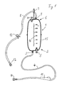
- the gassing container 1 of the blood gassing device shown in FIG. 1 has at its lower end 2 a connection 3 for a blood tube 4 and a connection 5 for a lower gas tube, not shown here.
- the arrangement of the blood or gas connections "at the end" of the gassing container 1 should not be understood to mean that they must be connected from below or from above. Of course, a supply is also possible, for example, radially from the side, as long as it is only ensured that the lower gas connection 5 is below the lowest in practice and the upper gas connection 7 is above the highest liquid level of the blood in practice.
- the gassing container 1 is suspended from an infusion frame (not shown) when it is used with a suitably molded suspension eye 9.
- a suitable coupling 10 for example a Luer lock connecting element for connection to an infusion needle, through which blood can be drawn from the patient.
- the suction speed can be metered with the aid of a roller clamp 11 which is customary in infusion technology.
- the vacuum in the container body 1 required for drawing in the blood can be generated by pumping out via the upper gas hose 8, which also expediently also has a Luer lock coupling 12 for connection to a corresponding device.
- the blood gassing device is preferably already evacuated at the factory and made available to the user as a ready-to-use, disposable item.
- a roller clamp 11 which is vacuum-tight in the closed state is used for the blood tube 4.
- the gas hose 8 is shut off by a vacuum-sealing clamping element 13.
- the hoses 4, 8 are permanently connected to the corresponding connections 3, 7, for example by gluing.
- the container body 1 is of course vacuum-tight.
- the container body 15 of the container 1 expediently consists of a transparent plastic material, in particular acrylic glass (plexiglass) with a scale 16, with the aid of which the amount of blood drawn in can be easily checked.
- ozone is conducted into the gas space above the blood surface under slightly increased pressure. This is done with the aid of the hose 8, which is connected via the coupling 12 to a suitable device, for example the "Humazon” device from Technomed GmbH, Weingarten, Federal Republic of Germany.
- a gas hose (not shown here) is connected to the lower gas hose connection 5.
- the gas flows through the blood and escapes through the upper gas hose 8.
- a hydrophobic filter element which on the one hand allows the gas to flow from the outside into the interior of the fumigation container and on the other hand is impermeable to blood.
- Such hydrophobic filter elements are commercially available for other purposes.
- the product 0.2 ⁇ m hydrophobic from Schleicher & Schuell, 3354 Dassel, Federal Republic of Germany is suitable.
- the invention generally relates to any filter element which fulfills the conditions mentioned (gas permeability, blood impermeability) and is physiologically harmless.
- a gassing hose can be connected to the gas hose connection 5 in various ways, for example again using a Luer lock connection. Particularly preferred is, however, a design as a vaccination valve, as shown enlarged in Fig. 3.
- the inoculation valve 20 has a pipe socket 21 which is inserted in a gas-tight manner (for example glued) into the wall 22 of the container body 15.
- the recess 23 of the pipe socket 21 is closed to the outside by a puncture seal in the form of a sealing plate 24 made of rubber-elastic material, which is tightly connected to the pipe socket 21, for example — as shown — by means of a clamping ring 25.
- the recess 23 formed here by an inwardly curved shape of the wall 22 is closed off by the hydrophobic filter element 26.
- the hydrophobic filter element 26 In the case shown, it consists of a plastic sleeve 26a and a hydrophobic filter 26b enclosed therein, which has the permeability properties mentioned.
- a press seal is sufficient for sealing between the hydrophobic filter element 26 and the inner wall of the connector 21, but an adhesive connection can also be selected here for safety reasons.
- FIG. 3 Also shown schematically in FIG. 3 is the end of a lower gas hose 27 with a puncture cannula 28.
- the connection between the gas hose 27 and the container can be made simply by piercing the cannula 28 into the puncture seal 24.
- the vaccination valve 20 has a puncture stop 30.
- it can simply consist of the Stub 21 is longer than the cannula 28, so that its head piece 29, which of course must be larger than the diameter of the recess 23, abuts against the stub 21, thereby limiting the penetration depth.
- this principle only works if the length of the socket is matched to the length of the cannulas 28 used.
- a puncture stop 30 is preferred with at least two locking elements 31, 32 projecting into the passage opening, which, as can be seen from FIGS. 2 and 3, are axially offset from one another.
- the front edges 31a and 32a (FIG. 4) of the locking elements 31, 32 lie in the same plane parallel to the axis of the connector 21.
- FIG. 5 shows the mouth of the blood tube connection 3 in a view from the direction of the arrow 35. This extends to the inside of the container in the form of a funnel 36. Radially arranged webs 37 serve to support a filter sieve 38 (FIG. 2) which is welded at its edge or gluing is connected to the container body 15.
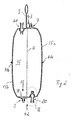
- the container body 15 advantageously consists of two identical parts 15a and 15b.
- the upper gas hose connection 7 is identical to the blood hose connection 3, but the filter screen 38 is not necessary and can therefore be omitted.
- a second injection valve 40 is expediently provided at the upper end of the container 1, which is designed like the first injection valve 20, but has no hydrophobic filter element.
- it can be used to deliver drugs, in particular anticoagulants, using a syringe.
- the connecting flange 41a, 41b is expediently designed in a special way. Its profiling is divided into two, one half of the circumference having a projecting profile and the other half having the same diameter range in a corresponding projecting profile.
- the housing shape shown in FIG. 2 has also proven to be expedient. It is advantageous if, in the illustrated substantially cylindrical shape of the container body 15, its end faces 42, 43 which run vertically to the axis A are relatively small and gradually change to the full container diameter with a rounded shape. In its general form, however, the invention is not limited to the essentially cylindrical shape shown.
Landscapes
- Health & Medical Sciences (AREA)
- Heart & Thoracic Surgery (AREA)
- Emergency Medicine (AREA)
- Animal Behavior & Ethology (AREA)
- Public Health (AREA)
- Engineering & Computer Science (AREA)
- Anesthesiology (AREA)
- Biomedical Technology (AREA)
- Hematology (AREA)
- Life Sciences & Earth Sciences (AREA)
- Urology & Nephrology (AREA)
- General Health & Medical Sciences (AREA)
- Vascular Medicine (AREA)
- Veterinary Medicine (AREA)
- Infusion, Injection, And Reservoir Apparatuses (AREA)
- Catching Or Destruction (AREA)
- Agricultural Chemicals And Associated Chemicals (AREA)
- Medical Preparation Storing Or Oral Administration Devices (AREA)
- External Artificial Organs (AREA)
- Storage Of Fruits Or Vegetables (AREA)
Applications Claiming Priority (4)
| Application Number | Priority Date | Filing Date | Title |
|---|---|---|---|
| DE8810552 | 1988-08-20 | ||
| DE8810552U | 1988-08-20 | ||
| DE8901513U | 1989-02-10 | ||
| DE8901513U DE8901513U1 (de) | 1988-08-20 | 1989-02-10 | Blutbegasungsvorrichtung |
Publications (3)
| Publication Number | Publication Date |
|---|---|
| EP0355456A2 true EP0355456A2 (fr) | 1990-02-28 |
| EP0355456A3 EP0355456A3 (fr) | 1991-05-08 |
| EP0355456B1 EP0355456B1 (fr) | 1995-01-04 |
Family
ID=25953433
Family Applications (1)
| Application Number | Title | Priority Date | Filing Date |
|---|---|---|---|
| EP89113830A Expired - Lifetime EP0355456B1 (fr) | 1988-08-20 | 1989-07-27 | Dispositif pour le traitement du sang avec un gaz |
Country Status (5)
| Country | Link |
|---|---|
| US (1) | US5108702A (fr) |
| EP (1) | EP0355456B1 (fr) |
| AT (1) | ATE116557T1 (fr) |
| DE (2) | DE8901513U1 (fr) |
| ES (1) | ES2069554T3 (fr) |
Cited By (1)
| Publication number | Priority date | Publication date | Assignee | Title |
|---|---|---|---|---|
| WO1995015188A1 (fr) * | 1993-12-01 | 1995-06-08 | Waltraud Kockerols | Systeme de raccordement d'un appareil d'ozonotherapie hyperbare sur un patient |
Families Citing this family (8)
| Publication number | Priority date | Publication date | Assignee | Title |
|---|---|---|---|---|
| US5303751A (en) * | 1991-10-04 | 1994-04-19 | Fresenius Ag | Spiked bag packaging system |
| JPH0852196A (ja) * | 1994-08-09 | 1996-02-27 | Material Eng Tech Lab Inc | 薬剤連結口を有する輸液容器 |
| US5554123A (en) * | 1994-10-31 | 1996-09-10 | Glenn Herskowitz | Portable infusion pump |
| DE19506163C2 (de) * | 1995-02-22 | 1998-01-29 | Hans Mueller | Vorrichtung zur Behandlung von Blut |
| US6162206A (en) | 1997-12-23 | 2000-12-19 | Baxter International Inc. | Resealable access site |
| US6179821B1 (en) * | 1998-06-18 | 2001-01-30 | Glenn A. Caspary | Membrane port for a container |
| US6726672B1 (en) * | 1998-09-28 | 2004-04-27 | Icu Medical, Inc. | Intravenous drug access system |
| DE60326847D1 (de) | 2002-06-24 | 2009-05-07 | Gambro Lundia Ab | Gastrennvorrichtung |
Family Cites Families (9)
| Publication number | Priority date | Publication date | Assignee | Title |
|---|---|---|---|---|
| US3175555A (en) * | 1960-03-14 | 1965-03-30 | Abbott Lab | Apparatus for treating blood |
| US3492991A (en) * | 1967-02-23 | 1970-02-03 | Richard H Dyer Jr | Autotransfusion apparatus |
| US3467095A (en) * | 1967-04-24 | 1969-09-16 | Eugene Ross Lab Inc | Blood collection set |
| JPS4923711B1 (fr) * | 1969-07-08 | 1974-06-18 | ||
| US3908653A (en) * | 1974-01-23 | 1975-09-30 | Vital Assists | Blood chamber |
| DE2817456A1 (de) * | 1978-04-21 | 1979-10-31 | Bayer Ag | Verfahren zur herstellung von thermoplastischen polyurethanelastomeren |
| DE3232716A1 (de) * | 1982-09-03 | 1984-03-08 | Arthur 2200 Elmshorn Lindner | Vorrichtung zur sauerstoffanreicherung von blut |
| US4639316A (en) * | 1984-12-14 | 1987-01-27 | Becton, Dickinson And Company | Automatic liquid component separator |
| US4810378A (en) * | 1986-04-21 | 1989-03-07 | Miles Laboratories, Inc. | Red blood cell filtering system |
-
1989
- 1989-02-10 DE DE8901513U patent/DE8901513U1/de not_active Expired
- 1989-07-27 EP EP89113830A patent/EP0355456B1/fr not_active Expired - Lifetime
- 1989-07-27 AT AT89113830T patent/ATE116557T1/de not_active IP Right Cessation
- 1989-07-27 ES ES89113830T patent/ES2069554T3/es not_active Expired - Fee Related
- 1989-07-27 DE DE58908846T patent/DE58908846D1/de not_active Expired - Lifetime
- 1989-08-04 US US07/389,509 patent/US5108702A/en not_active Expired - Fee Related
Cited By (1)
| Publication number | Priority date | Publication date | Assignee | Title |
|---|---|---|---|---|
| WO1995015188A1 (fr) * | 1993-12-01 | 1995-06-08 | Waltraud Kockerols | Systeme de raccordement d'un appareil d'ozonotherapie hyperbare sur un patient |
Also Published As
| Publication number | Publication date |
|---|---|
| DE8901513U1 (de) | 1989-04-06 |
| EP0355456A3 (fr) | 1991-05-08 |
| US5108702A (en) | 1992-04-28 |
| ATE116557T1 (de) | 1995-01-15 |
| ES2069554T3 (es) | 1995-05-16 |
| DE58908846D1 (de) | 1995-02-16 |
| EP0355456B1 (fr) | 1995-01-04 |
Similar Documents
| Publication | Publication Date | Title |
|---|---|---|
| DE69215922T2 (de) | Übertragungsansclussstück | |
| DE1498600C2 (de) | Selbstabdichtender, durchstechbarer Stöpsel aus elastomerem Material | |
| EP0786262B1 (fr) | Aiguille de connection pour l'utilisation avec un dispositif de traitement du sang | |
| DE69231208T2 (de) | Medizinisches ventil | |
| EP1616594B1 (fr) | Système de ponction avec un tube flexible permanent raccordé à un système d'alimentation médical | |
| DE3143329C2 (de) | Schutzvorrichtung für einen Verbindungsstöpsel von medizinischen Schlauchsystemen | |
| DE2525713C2 (de) | Vorrichtung zur Überführung von Blut aus einem Probenbehälter in ein Pipettenröhrchen | |
| DE2835101C2 (fr) | ||
| DE69723278T2 (de) | Pharmazeutische ampulle | |
| EP1171347B1 (fr) | Procede et dispositif de remplissage d'injecteurs sans aiguille | |
| EP0584396A1 (fr) | Raccord pour disconnecter et reconnecter l'écoulement d'un fluide | |
| DE2824588A1 (de) | Einweg-stopfen fuer vakuumroehrchen | |
| EP2465558A1 (fr) | Dispositif pour l'extraction d'un liquide d'un récipient | |
| DE2731946A1 (de) | Schutzkappe fuer einen behaelterzulass oder -fuellstutzen | |
| DE3414079A1 (de) | Medizinischer behaelter | |
| EP2305790B1 (fr) | Dispositif destiné au prélèvement d'échantillons | |
| DE69003327T2 (de) | Injektionsstelle. | |
| EP0111723A1 (fr) | Raccord pour injections extemporanées dans un système de perfusion ou de transfusion | |
| DE69316732T2 (de) | Behälter für Lösungen mit Verbindungsschlauch aus Kunststoff | |
| EP0355456B1 (fr) | Dispositif pour le traitement du sang avec un gaz | |
| DE102009023676B4 (de) | Vorrichtung zur Applikation fluidaler Medikamente | |
| DE2617083A1 (de) | Spritzampulle und verfahren zu deren fuellung | |
| EP0441171A2 (fr) | Dispositif médical avec barrière à germe | |
| DE102023135598A1 (de) | Medizinisches Infusionsset und Verfahren zu dessen Herrichtung für den Gebrauch | |
| DE102020102657B3 (de) | Spritze |
Legal Events
| Date | Code | Title | Description |
|---|---|---|---|
| PUAI | Public reference made under article 153(3) epc to a published international application that has entered the european phase |
Free format text: ORIGINAL CODE: 0009012 |
|
| AK | Designated contracting states |
Kind code of ref document: A2 Designated state(s): AT DE ES FR GB IT SE |
|
| PUAL | Search report despatched |
Free format text: ORIGINAL CODE: 0009013 |
|
| RHK1 | Main classification (correction) |
Ipc: A61M 1/32 |
|
| AK | Designated contracting states |
Kind code of ref document: A3 Designated state(s): AT DE ES FR GB IT SE |
|
| 17P | Request for examination filed |
Effective date: 19911007 |
|
| 17Q | First examination report despatched |
Effective date: 19930217 |
|
| GRAA | (expected) grant |
Free format text: ORIGINAL CODE: 0009210 |
|
| AK | Designated contracting states |
Kind code of ref document: B1 Designated state(s): AT DE ES FR GB IT SE |
|
| REF | Corresponds to: |
Ref document number: 116557 Country of ref document: AT Date of ref document: 19950115 Kind code of ref document: T |
|
| REF | Corresponds to: |
Ref document number: 58908846 Country of ref document: DE Date of ref document: 19950216 |
|
| ITF | It: translation for a ep patent filed | ||
| PG25 | Lapsed in a contracting state [announced via postgrant information from national office to epo] |
Ref country code: SE Effective date: 19950404 |
|
| GBT | Gb: translation of ep patent filed (gb section 77(6)(a)/1977) |
Effective date: 19950406 |
|
| ET | Fr: translation filed | ||
| REG | Reference to a national code |
Ref country code: ES Ref legal event code: FG2A Ref document number: 2069554 Country of ref document: ES Kind code of ref document: T3 |
|
| PLBE | No opposition filed within time limit |
Free format text: ORIGINAL CODE: 0009261 |
|
| STAA | Information on the status of an ep patent application or granted ep patent |
Free format text: STATUS: NO OPPOSITION FILED WITHIN TIME LIMIT |
|
| 26N | No opposition filed | ||
| PGFP | Annual fee paid to national office [announced via postgrant information from national office to epo] |
Ref country code: AT Payment date: 19970715 Year of fee payment: 9 Ref country code: GB Payment date: 19970715 Year of fee payment: 9 |
|
| PGFP | Annual fee paid to national office [announced via postgrant information from national office to epo] |
Ref country code: ES Payment date: 19970728 Year of fee payment: 9 |
|
| PGFP | Annual fee paid to national office [announced via postgrant information from national office to epo] |
Ref country code: FR Payment date: 19970729 Year of fee payment: 9 |
|
| PG25 | Lapsed in a contracting state [announced via postgrant information from national office to epo] |
Ref country code: GB Free format text: LAPSE BECAUSE OF NON-PAYMENT OF DUE FEES Effective date: 19980727 Ref country code: AT Free format text: LAPSE BECAUSE OF NON-PAYMENT OF DUE FEES Effective date: 19980727 |
|
| PG25 | Lapsed in a contracting state [announced via postgrant information from national office to epo] |
Ref country code: ES Free format text: LAPSE BECAUSE OF EXPIRATION OF PROTECTION Effective date: 19980728 |
|
| GBPC | Gb: european patent ceased through non-payment of renewal fee |
Effective date: 19980727 |
|
| PG25 | Lapsed in a contracting state [announced via postgrant information from national office to epo] |
Ref country code: FR Free format text: LAPSE BECAUSE OF NON-PAYMENT OF DUE FEES Effective date: 19990331 |
|
| REG | Reference to a national code |
Ref country code: FR Ref legal event code: ST |
|
| REG | Reference to a national code |
Ref country code: ES Ref legal event code: FD2A Effective date: 20010201 |
|
| PG25 | Lapsed in a contracting state [announced via postgrant information from national office to epo] |
Ref country code: IT Free format text: LAPSE BECAUSE OF NON-PAYMENT OF DUE FEES;WARNING: LAPSES OF ITALIAN PATENTS WITH EFFECTIVE DATE BEFORE 2007 MAY HAVE OCCURRED AT ANY TIME BEFORE 2007. THE CORRECT EFFECTIVE DATE MAY BE DIFFERENT FROM THE ONE RECORDED. Effective date: 20050727 |
|
| PGFP | Annual fee paid to national office [announced via postgrant information from national office to epo] |
Ref country code: DE Payment date: 20080703 Year of fee payment: 20 |