EP0355532B1 - Anordnung zum Übertragen von Daten und einer Versorgungsspannung über eine Busleitung - Google Patents
Anordnung zum Übertragen von Daten und einer Versorgungsspannung über eine Busleitung Download PDFInfo
- Publication number
- EP0355532B1 EP0355532B1 EP89114465A EP89114465A EP0355532B1 EP 0355532 B1 EP0355532 B1 EP 0355532B1 EP 89114465 A EP89114465 A EP 89114465A EP 89114465 A EP89114465 A EP 89114465A EP 0355532 B1 EP0355532 B1 EP 0355532B1
- Authority
- EP
- European Patent Office
- Prior art keywords
- arrangement
- supply voltage
- bus line
- devices
- windings
- Prior art date
- Legal status (The legal status is an assumption and is not a legal conclusion. Google has not performed a legal analysis and makes no representation as to the accuracy of the status listed.)
- Expired - Lifetime
Links
Images

Classifications
-
- H—ELECTRICITY
- H04—ELECTRIC COMMUNICATION TECHNIQUE
- H04L—TRANSMISSION OF DIGITAL INFORMATION, e.g. TELEGRAPHIC COMMUNICATION
- H04L12/00—Data switching networks
- H04L12/02—Details
- H04L12/10—Current supply arrangements
-
- H—ELECTRICITY
- H04—ELECTRIC COMMUNICATION TECHNIQUE
- H04B—TRANSMISSION
- H04B3/00—Line transmission systems
- H04B3/54—Systems for transmission via power distribution lines
- H04B3/548—Systems for transmission via power distribution lines the power on the line being DC
-
- G—PHYSICS
- G05—CONTROLLING; REGULATING
- G05B—CONTROL OR REGULATING SYSTEMS IN GENERAL; FUNCTIONAL ELEMENTS OF SUCH SYSTEMS; MONITORING OR TESTING ARRANGEMENTS FOR SUCH SYSTEMS OR ELEMENTS
- G05B2219/00—Program-control systems
- G05B2219/20—Pc systems
- G05B2219/23—Pc programming
- G05B2219/23375—Function switch, knob with piezo, strain gauge
-
- G—PHYSICS
- G05—CONTROLLING; REGULATING
- G05B—CONTROL OR REGULATING SYSTEMS IN GENERAL; FUNCTIONAL ELEMENTS OF SUCH SYSTEMS; MONITORING OR TESTING ARRANGEMENTS FOR SUCH SYSTEMS OR ELEMENTS
- G05B2219/00—Program-control systems
- G05B2219/20—Pc systems
- G05B2219/24—Pc safety
- G05B2219/24028—Explosion free control, intrinsically safe
-
- G—PHYSICS
- G05—CONTROLLING; REGULATING
- G05B—CONTROL OR REGULATING SYSTEMS IN GENERAL; FUNCTIONAL ELEMENTS OF SUCH SYSTEMS; MONITORING OR TESTING ARRANGEMENTS FOR SUCH SYSTEMS OR ELEMENTS
- G05B2219/00—Program-control systems
- G05B2219/20—Pc systems
- G05B2219/25—Pc structure of the system
- G05B2219/25188—Superposition high frequency data signal on power lines, current carrier
-
- G—PHYSICS
- G05—CONTROLLING; REGULATING
- G05B—CONTROL OR REGULATING SYSTEMS IN GENERAL; FUNCTIONAL ELEMENTS OF SUCH SYSTEMS; MONITORING OR TESTING ARRANGEMENTS FOR SUCH SYSTEMS OR ELEMENTS
- G05B2219/00—Program-control systems
- G05B2219/20—Pc systems
- G05B2219/25—Pc structure of the system
- G05B2219/25462—Galvanic separation, galvanic isolation
-
- H—ELECTRICITY
- H04—ELECTRIC COMMUNICATION TECHNIQUE
- H04B—TRANSMISSION
- H04B2203/00—Indexing scheme relating to line transmission systems
- H04B2203/54—Aspects of powerline communications not already covered by H04B3/54 and its subgroups
- H04B2203/5462—Systems for power line communications
- H04B2203/547—Systems for power line communications via DC power distribution
-
- H—ELECTRICITY
- H04—ELECTRIC COMMUNICATION TECHNIQUE
- H04B—TRANSMISSION
- H04B2203/00—Indexing scheme relating to line transmission systems
- H04B2203/54—Aspects of powerline communications not already covered by H04B3/54 and its subgroups
- H04B2203/5462—Systems for power line communications
- H04B2203/5483—Systems for power line communications using coupling circuits
-
- H—ELECTRICITY
- H04—ELECTRIC COMMUNICATION TECHNIQUE
- H04L—TRANSMISSION OF DIGITAL INFORMATION, e.g. TELEGRAPHIC COMMUNICATION
- H04L12/00—Data switching networks
- H04L12/28—Data switching networks characterised by path configuration, e.g. LAN [Local Area Networks] or WAN [Wide Area Networks]
- H04L12/40—Bus networks
- H04L2012/40208—Bus networks characterized by the use of a particular bus standard
Definitions
- DE-B-21 13 931 describes an arrangement in which a plurality of receivers are connected to a central unit via a two-wire line, via which pulses and the supply voltage for the respective receiver are transmitted.
- the pulses are fed into and taken from the lines by means of differential transformers.
- the differential windings of the transformers are alternately connected in series by means of a capacitor.
- a transformer which has a secondary winding and a rectifier connected to it, is used to power the receivers.
- the DC voltages are applied to the capacitors connecting the differential windings and taken off in the receivers at the corresponding capacitors connected to the differential windings.
- the known arrangement is only suitable for a galvanic separation of transmitter and receiver for a star-shaped connection of the receiver to the central unit, but not for a bus line connecting all receivers and the central unit.
- EP-A-0 134 174 describes a bus system in which the pulses containing the information modulate a DC voltage serving as the supply voltage. There is no electrical isolation between the participants in the bus system.
- the present invention has for its object to provide an arrangement of the type specified in the preamble of claim 1, the devices of which are electrically isolated from a bus line.
- the new arrangement is used with particular advantage in process and process engineering when intrinsically safe and explosion-protected field devices that are spatially separated from one another are to be connected to a remote control center with little effort.
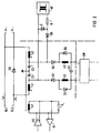
- BL1, BL2 are the two wires of a two-wire bus line to which several devices ST1, ST2 ... STn, z. B. digitally working sensors and actuators are connected. To and from these digital measurement and control signals as well as further data such as status and error messages, parameters and so on are to be transmitted.
- the bus line is not only used to transmit information, but also to supply power to the devices. Since the bus line is to be galvanically isolated from the devices and, of course, the devices are to be galvanically isolated from each other, each device contains a transformer for coupling information signals into and out of the bus line.
- the transformers each have three windings W11, W12, W13; W21, W22, W23 ... Wn1, Wn2, Wn3 on.
- the two windings connected to the bus lines are connected in series with capacitors C11, C12, C21, C22 ... Cn1, Cn2.
- the transmitting and receiving devices are connected to the third windings W13, W23 ... Wn
- the devices are supplied with energy by a power supply unit SV via the bus line BL1, BL2.
- the power supply unit SV is also to be electrically isolated from the bus line, it contains a network transformer, the rectified output voltage of which is screened by means of a capacitor C0 and fed via coils SP1, SP2 into the bus line BL1, BL2.
- the devices ST1, ST2 ... STn contain direct voltage converters SW1, SW2 ... SWn, which are connected to the series connection of the capacitors Ci1, Ci2 and receive the supply voltage from the bus line BL1, BL2 via the windings Wi1, Wi2.
- the transformer windings and the capacitors act as filter elements for the supply voltage.
- the power supply unit is expediently not connected separately to the bus line, but is part of a device, for. B. a central unit, and is connected in this like the voltage converter SW1, SW2 ... SWn to the capacitors Ci1, Ci2.
- the function of the coils SP1, SP2 and the capacitor C0 is then taken over by the transformer windings and capacitors which are present in the device anyway.
- BL1, BL2 again designate the two wires of the bus line on which the information signals are transmitted in phase opposition. There is also a positive supply voltage V + on bus line BL1 and a negative V- on bus line BL2.
- a series connection of two transformer windings L1, L2 with the same number of turns and two capacitors C1, C2 with the same capacitance lies between the wires BL1, BL2.
- a reception amplifier V1, which is a differential amplifier, and a transmission amplifier V2 as a line driver, which feeds signals in phase opposition to the winding L3, are connected to a third winding L3 of the transformer.
- a resistor Z L is expediently connected to the winding L3, which, taking into account the reduction ratio of the transformer, is dimensioned such that the bus line with the characteristic impedance closed is.
- Such an arrangement has the advantage over a direct termination of the bus line with a resistor that no additional supply current is consumed.
- the gear ratio between the winding L3 and the windings L1, L2 is greater than one, the characteristic impedance is transformed in the ratio of the square of the gear ratio.
- the ohmic resistance Z L is greater than the characteristic impedance and therefore loads the line driver V2 accordingly low. This also saves energy.
- the same line drivers can be used for all line drivers, regardless of whether the associated devices form the termination of the bus line or not.
- a DC voltage converter SW supplies a supply voltage for the device that is electrically isolated from the bus line.
- z. B a voltage converter, which switches the input voltage with different polarity alternately to the primary winding of a transformer, to the secondary winding of which a rectifier with a downstream filter element is connected.
- DC / DC converters require a large energy store, which in the exemplary embodiment is formed by a capacitor C3, which is supplemented with a filter with chokes L2, L3, to which freewheeling diodes D3, D4 are connected in parallel. So that the capacitor C3 is not in the event of a voltage drop on the bus line, for. B.
- diodes D2, D3 are connected in its feed lines. Voltage peaks that can occur on the windings L1, L2 in the event of a sudden voltage drop on the bus line are prevented from the bus line by a diode D1. In contrast, the series connection of the capacitors C1, C2 remains effective, but their charge cannot flow suddenly into the bus line in the event of a short circuit on the bus line due to the inductance of the windings L1, L2.
- Any power supply unit contained in the device has a power supply unit NT with a power transformer, the Output current by means of a resistor R and its output voltage by means of a Zener diode Z are limited. This is possible if several power supply units are to be used for redundancy of the power supply or to avoid an inadmissibly large voltage drop on the bus line due to its ohmic resistance. However, a diode D5 must be provided for each power supply unit for mutual decoupling. It must also be ensured that the total current of all power supply units does not exceed the maximum permissible value even in the event of a short circuit on the bus line.
- the device connection described is suitable for bus systems that are used in potentially explosive areas. As already described, measures are taken in every device connection to suppress impermissible current and voltage peaks. Unsafe components in vulnerable areas, such as B. the diodes D1, D3, D4, can be carried out twice and other components, such as. B. the electrolytic capacitor C3, are protected by potting. The output current and the output voltage of the power supply unit are limited.
- FIG. 3 shows a bus line system whose bus line consists of a two-wire shielded line BL3.
- the devices not designated again each contain a signal transmitter, which with two windings L01, L02; L11, L12; ... Ln1, Ln2 is connected to the wires of the bus line.
- the center taps of these windings are capacitively on the shield of the bus line.
- the supply voltage is fed into the bus line via windings L01, L02, the middle of the supply voltage can be connected to the screen.
- the direct current does not magnetize the transformer core because the windings are bifilar.
- For the information signal however, which is applied to the wires in phase, they act like a differential transformer. In contrast to that according to FIG.
- this circuit is dependent on the shield line or another third conductor, but also works strictly symmetrically. Common mode disturbances have no effect.
- the circuit is suitable for transmitting signals over longer distances in interference fields with a high data transmission rate.
- the circuit according to FIG. 2 can be used to connect the voltage converters of the devices.
- the auxiliary power transmission can be chosen larger here, since the transformer does not become saturated by premagnetization.
Landscapes
- Engineering & Computer Science (AREA)
- Computer Networks & Wireless Communication (AREA)
- Signal Processing (AREA)
- Power Engineering (AREA)
- Cable Transmission Systems, Equalization Of Radio And Reduction Of Echo (AREA)
- Semiconductor Integrated Circuits (AREA)
- Arrangements For Transmission Of Measured Signals (AREA)
- Dc Digital Transmission (AREA)
Description
- In der DE-B- 21 13 931 ist eine Anordnung beschrieben, in der mehrere Empfänger mit einer Zentraleinheit über je eine Zweidrahtleitung verbunden sind, über die Impulse und die Versorgungsspannung für den jeweiligen Empfänger übertragen werden. Die Impulse werden mittels Differentialübertrager in die Leitungen eingespeist und aus diesen entnommen. Die Differentialwicklungen der Übertrager sind wechselstrommäßig mittels eines Kondensators in Reihe geschaltet. Zur Stromversorgung der Empfänger dient ein Transformator, der je Empfänger eine Sekundärwicklung und einen an diese angeschlossenen Gleichrichter aufweist. Die Gleichspannungen werden an den die Differentialwicklungen verbindenden Kondensatoren angelegt und in den Empfängern an den entsprechenden, mit den Differentialwicklungen verbundenen Kondensatoren abgenommen. Die bekannte Anordnung ist bei galvanischer Trennung von Sender und Empfänger nur für einen sternförmigen Anschluß der Empfänger an die Zentraleinheit geeignet, nicht dagegen für eine alle Empfänger und die Zentrale verbindende Busleitung.
- In der EP-A- 0 134 174 ist ein Bussystem beschrieben, bei dem die die Informationen enthaltenden Impulse eine als Versorgungsspannung dienende Gleichspannung modulieren. Eine galvanische Trennung zwischen den Teilnehmern des Bussystems ist nicht vorgesehen.
- Der vorliegenden Erfindung liegt die Aufgabe zugrunde, eine Anordnung der im Oberbegriff des Anspruchs 1 angegebenen Art zu schaffen, deren Geräte an eine Busleitung galvanisch getrennt angeschlossen sind.
- Erfindungsgemäß wird diese Aufgabe mit den im kennzeichnenden Teil des Anspruchs 1 angegebenen Maßnahmen gelöst.
- Die neue Anordnung wird mit besonderem Vorteil in der Verfahrens- und Prozeßtechnik eingesetzt, wenn räumlich voneinander entfernt liegende Feldgeräte eigensicher und explosionsgeschützt mit geringem Aufwand an eine entfernte Zentrale angeschlossen werden sollen.
- Anhand der Zeichnung werden im folgenden die Erfindung sowie deren Ausgestaltungen und Ergänzungen näher beschrieben und erläutert.
- Es zeigen
- die Figuren 1 und 3
- Schaltbilder von Ausführungsbeispielen der Erfindung,
- Figur 2
- Einzelheiten des Ausführungsbeispiels nach Figur 1.
- In Figur 1 sind mit BL1, BL2 die beiden Adern einer zweiadrigen Busleitung bezeichnet, an die mehrere Geräte ST1, ST2 ... STn, z. B. digital arbeitende Sensoren und Aktoren, angeschlossen sind. Zu und von diesen sollen digitale Meß- und Stellsignale sowie weitere Daten, wie Status- und Fehlermeldungen, Parameter und so fort übertragen werden. Die Busleitung dient nicht nur zur Übertragung von Informationen, sondern auch zur Spannungsversorgung der Geräte. Da die Busleitung galvanisch von den Geräten und selbstverständlich auch die Geräte untereinander galvanisch getrennt sein sollen, enthält jedes Gerät einen Übertrager zum Ein- und Auskoppeln von Informationssignalen in die bzw. aus der Busleitung. Die Übertrager weisen je drei Wicklungen W11, W12, W13; W21, W22, W23 ... Wn1, Wn2, Wn3 auf. Die beiden an die Busleitungen angeschlossenen Wicklungen sind wechselstrommäßig mit Kondensatoren C11, C12, C21, C22 ... Cn1, Cn2 in Reihe geschaltet. An die dritten Wicklungen W13, W23 ... Wn3 sind die Sende- und Empfangseinrichtungen angeschlossen.
- Die Geräte werden von einer Stromversorgungseinheit SV über die Busleitung BL1, BL2 mit Energie versorgt. Da im Ausführungsbeispiel auch die Stromversorgungseinheit SV galvanisch von der Busleitung getrennt sein soll, enthält sie einen Netztransformator, dessen gleichgerichtete Ausgangsspannung mittels eines Kondensators C0 gesiebt über Spulen SP1, SP2 in die Busleitung BL1, BL2 eingespeist wird. Die Geräte ST1, ST2 ... STn enthalten Gleichspannungswandler SW1, SW2 ... SWn, die an die Reihenschaltung der Kondensatoren Ci1, Ci2 angeschlossen sind und von der Busleitung BL1, BL2 die Versorgungsspannung über die Wicklungen Wi1, Wi2 erhalten. Die Übertragerwicklungen und die Kondensatoren wirken für die Versorgungsspannung als Siebglieder.
- Zweckmäßig ist die Stromversorgungseinheit nicht gesondert an die Busleitung angeschlossen, sondern sie ist Bestandteil eines Gerätes, z. B. einer Zentraleinheit, und ist in diesem wie die Spannungswandler SW1, SW2 ... SWn an die Kondensatoren Ci1, Ci2 angeschlossen. Die Funktion der Spulen SP1, SP2 und des Kondensators C0 wird dann von den in dem Gerät ohnedies vorhandenen Übertragerwicklungen und Kondensatoren übernommen.
- Einzelheiten einer vorteilhaften Anschaltung der Geräte, insbesondere der Spannungswandler an die Busleitung, zeigt das Schaltbild nach Figur 2. Mit BL1, BL2 sind wieder die beiden Adern der Busleitung bezeichnet, auf denen die Informationssignale gegenphasig übertragen werden. Auf der Busleitung BL1 liegt ferner eine positive Versorgungsspannung V+, auf der Busleitung BL2 eine negative V-. Eine Reihenschaltung aus zwei Übertragerwicklungen L1, L2 mit gleicher Windungszahl und zwei Kondensatoren C1, C2 mit gleicher Kapazität liegt zwischen den Adern BL1, BL2. An einer dritten Wicklung L3 des Übertragers liegen ein Empfangsverstärker V1, der ein Differenzverstärker ist, und ein Sendeverstärker V2 als Leitungstreiber, der gegenphasige Signale in die Wicklung L3 speist.
- Befindet sich das Gerät am Ende der Busleitung, wie z. B. das Gerät STn in der Anordnung nach Figur 1, wird zweckmäßig an die Wicklung L3 ein Widerstand ZL angeschlossen, der, unter Berücksichtigung des Untersetzungsverhältnisses des Übertragers, so bemessen ist, daß die Busleitung mit dem Wellenwiderstand ab geschlossen ist. Eine solche Anordnung hat gegenüber einem unmittelbaren Abschluß der Busleitung mit einem Widerstand den Vorteil, daß kein Versorgungsstrom zusätzlich verbraucht wird. Wenn das Übersetzungsverhältnis zwischen der Wicklung L3 und den Wicklungen L1, L2 größer als Eins ist, wird der Wellenwiderstand im Verhältnis des Quadrats des Übersetzungsverhältnisses transformiert. Dadurch wird der ohmsche Widerstand ZL größer als der Wellenwiderstand und belastet daher den Leitungstreiber V2 entsprechend gering. Auch hierdurch wird eine Energieeinsparung erreicht. Ferner können für alle Leitungstreiber, unabhängig, ob die zugehörigen Geräte den Abschluß der Busleitung bilden oder nicht, gleiche Leitungstreiber verwendet werden.
- Ein Gleichspannungswandler SW liefert eine von der Busleitung galvanisch getrennte Versorgungsspannung für das Gerät. Hierzu eignet sich z. B. ein Spannungswandler, der die Eingangsspannung mit unterschiedlicher Polung abwechselnd auf die Primärwicklung eines Übertragers schaltet, an dessen Sekundärwicklung ein Gleichrichter mit einem nachgeschalteten Siebglied angeschlossen ist. Im allgemeinen erfordern solche Gleichspannungswandler einen großen Energiespeicher, der im Ausführungsbeispiel von einem Kondensator C3 gebildet ist, der mit Drosseln L2, L3, denen Freilaufdioden D3, D4 parallelgeschaltet sind, zu einem Filter ergänzt ist. Damit sich der Kondensator C3 nicht im Falle eines Spannungsabfalls auf der Busleitung, z. B. während der Impulse, oder im Falle eines Kurzschlusses entladen kann, sind in seine Zuleitungen Dioden D2, D3 geschaltet. Spannungsspitzen, die an den Wicklungen L1, L2 bei einem plötzlichen Spannungsabfall auf der Busleitung auftreten können, werden von einer Diode D1 von der Busleitung abgehalten. Wirksam bleibt dagegen die Serienschaltung der Kondensatoren C1, C2, deren Ladung aber im Falle eines Kurzschlusses auf der Busleitung wegen der Induktivität der Wicklungen L1, L2 nicht schlagartig in die Busleitung fließen kann.
- Eine etwaige, in dem Gerät enthaltene Stromversorgungseinheit weist ein Netzteil NT mit einem Netztransformator auf, dessen Ausgangsstrom mittels eines Widerstandes R und dessen Ausgangsspannung mittels einer Zenerdiode Z begrenzt sind. Sollen zwecks einer Redundanz der Stromversorgung oder zur Vermeidung eines unzulässig großen Spannungsabfalls auf der Busleitung wegen deren ohmschen Widerstandes mehrere Stromversorgungseinheiten verwendet werden, ist dies möglich. Zur gegenseitigen Entkopplung ist jedoch je Stromversorgungseinheit eine Diode D5 vorzusehen. Auch muß dafür gesorgt werden, daß der Gesamtstrom aller Stromversorgungseinheiten auch im Falle eines Kurzschlusses auf der Busleitung den maximal zulässigen Wert nicht übersteigt.
- Die beschriebene Geräteanschaltung eignet sich für Bussysteme, die in explosionsgefährdeten Bereichen eingesetzt werden. Wie schon beschrieben, sind in jeder Geräteanschaltung Maßnahmen getroffen, mit denen unzulässige Strom- und Spannungsspitzen unterdrückt werden. Nicht sichere Bauelemente an gefährdeten Stellen, wie z. B. die Dioden D1, D3, D4, können doppelt ausgeführt und andere Bauelemente, wie z. B. der Elektrolytkondensator C3, durch Verguß geschützt werden. Der Ausgangsstrom und die Ausgangsspannung der Stromversorgungseinheit sind begrenzt.
- Figur 3 zeigt ein Busleitungssystem, dessen Busleitung aus einer zweiadrigen geschirmten Leitung BL3 besteht. Die nicht bezeichneten Geräte enthalten wieder jeweils einen Signalübertrager, der mit zwei Wicklungen L01, L02; L11, L12;... Ln1, Ln2 an die Adern der Busleitung angeschlossen ist. Die Mittelanzapfungen dieser Wicklungen liegen kapazitiv am Schirm der Busleitung. Die Speisespannung wird in die Busleitung über die Wicklungen L01, L02 eingespeist, die Mitte der Speisespannung kann an den Schirm gelegt sein. Der Gleichstrom bewirkt keine Magnetisierung des Übertragerkerns, da die Wicklungen bifilar gewickelt sind. Für das Informationssignal aber, das gleichphasig auf die Adern gegeben wird, wirken sie wie ein Differenzübertrager. Diese Schaltung ist im Gegensatz zu der nach Figur 1 auf die Schirmleitung oder einen anderen dritten Leiter angewiesen, arbeitet aber auch streng symmetrisch. Gleichtaktstörungen wirken sich nicht aus. Die Schaltung eignet sich zum Übertragen von Signalen über größere Entfernungen in Störfeldern mit hoher Datenübertragungsrate. Für die Anschaltung der Spannungwandler der Geräte kann die Schaltung nach Figur 2 verwendet werden. Die Hilfsenergieübertragung kann hier größer gewählt werden, da der Übertrager nicht in die Sättigung durch Vormagnetisierung kommt.
Claims (11)
- Anordnung zum Übertragen von Daten zwischen mehreren Geräten und der Versorgungsspannung für die Geräte über eine Busleitung, an welche die Geräte und die Versorgungsspannungsquelle angeschlossen sind, dadurch gekennzeichnet, daß die Geräte (ST1, ST2 ... STn) an die Busleitung (BL1, BL2) jeweils mittels eines Übertragers (U1, U2 ... Un) angeschlossen sind, der zwei Wicklungen (Wi1, Wi2) gleicher Windungszahl aufweist, die mit ihren einen Anschlüssen mit der Busleitung (BL1, BL2) verbunden sind und zwischen deren anderen Anschlüssen eine Kapazität (Ci1, Ci2) liegt, an der die Versorgungsspannung abgenommen ist, daß an eine dritte Wicklung (Wi3) Sende- und Empfangseinrichtungen (V1, V2) angeschlossen sind und daß die Versorgungsspannungsquelle über zwei induktive Widerstände (SP1, SP2) an die Busleitung angeschlossen ist.
- Anordnung nach Anspruch 1, dadurch gekennzeichnet, daß die Versorgungsspannungsquelle in einem Gerät enthalten ist und die Versorgungsspannung zwischen den Übertragerwicklungen (Wi1, Wi2) und der Kapazität (Ci1, Ci2) eingespeist ist.
- Anordnung nach Anspruch 1 oder 2, dadurch gekennzeichnet, daß die Kapazität aus der Reihenschaltung von zwei Kondensatoren (Ci1, Ci2) gleicher Kapazität besteht, deren Verbindung an ein Bezugspotential angeschlossen ist.
- Anordnung nach einem der Ansprüche 1 bis 3, dadurch gekennzeichnet, daß die beiden Übertragerwicklungen (Wi1, Wi2) so gepolt sind, daß der Versorgungsstrom die Übertragerkerne in gleicher Richtung magnetisiert.
- Anordnung nach einem der Ansprüche 1 bis 3, dadurch gekennzeichnet, daß die beiden Wicklungen (Li1, Li2) der Übertrager so gepolt sind, daß die durch den Versorgungsstrom hervorgerufenen Magnetisierungen sich gegenseitig aufheben und daß die Busleitung eine dritte Ader, insbesondere einen Schirm, aufweist, mit dem die Verbindungen der Kondensatoren verbunden sind.
- Anordnung nach einem der Ansprüche 1 bis 5, dadurch gekennzeichnet, daß der Reihenschaltung aus den beiden Übertragerwicklungen und der Kapazität eine bezüglich der Versorgungsspannung in Sperrichtung betriebene Diode (D1) parallelgeschaltet ist.
- Anordnung nach einem der Ansprüche 1 bis 6, dadurch gekennzeichnet, daß die Versorgungsspannung über Dioden (D2, D3) abgenommen und einem als Energiespeicher dienenden Kondensator (C3) zugeführt ist.
- Anordnung nach Anspruch 7, dadurch gekennzeichnet, daß die Versorgungsspannung über Siebdrosseln (L2, L3) dem Kondensator (C3) zugeführt ist.
- Anordnung nach einem der Ansprüche 1 bis 8, dadurch gekennzeichnet, daß die Geräte (ST1, ST2 ... STn) je einen galvanisch trennenden Gleichspannungswandler (SW1, SW2 ..., SWn) enthalten, dessen Eingang die Versorgungsspannung von der Busleitung zugeführt ist und aus dem das jeweilige Gerät mit Strom versorgt ist.
- Anordnung nach einem der Ansprüche 1 bis 9, dadurch gekennzeichnet, daß an die dritte Wicklung (Wn3) des den Anschluß der Busleitung bildenden Gerätes (STn) ein Abschlußwiderstand (ZL) angeschlossen ist.
- Anordnung nach Anspruch 10, dadurch gekennzeichnet, daß die Windungszahl der dritten Wicklung (Wn3) größer als die Summe der Windungszahlen der beiden anderen Wicklungen (Wn1, Wn2) ist.
Applications Claiming Priority (2)
| Application Number | Priority Date | Filing Date | Title |
|---|---|---|---|
| DE3828272 | 1988-08-19 | ||
| DE3828272A DE3828272A1 (de) | 1988-08-19 | 1988-08-19 | Anordnung zum uebertragen von daten und einer versorgungsspannung ueber eine busleitung |
Publications (3)
| Publication Number | Publication Date |
|---|---|
| EP0355532A2 EP0355532A2 (de) | 1990-02-28 |
| EP0355532A3 EP0355532A3 (en) | 1990-05-09 |
| EP0355532B1 true EP0355532B1 (de) | 1994-10-26 |
Family
ID=6361238
Family Applications (1)
| Application Number | Title | Priority Date | Filing Date |
|---|---|---|---|
| EP89114465A Expired - Lifetime EP0355532B1 (de) | 1988-08-19 | 1989-08-04 | Anordnung zum Übertragen von Daten und einer Versorgungsspannung über eine Busleitung |
Country Status (4)
| Country | Link |
|---|---|
| EP (1) | EP0355532B1 (de) |
| AT (1) | ATE113430T1 (de) |
| DE (2) | DE3828272A1 (de) |
| ES (1) | ES2063085T3 (de) |
Cited By (9)
| Publication number | Priority date | Publication date | Assignee | Title |
|---|---|---|---|---|
| DE19520596A1 (de) * | 1995-06-06 | 1996-12-12 | Siemens Ag | Anordnung zum Übertragen von Daten und Energie über eine Busleitung |
| DE19630614A1 (de) * | 1996-07-29 | 1998-02-05 | Siemens Ag | Schaltanlage |
| US7447144B2 (en) | 2000-09-21 | 2008-11-04 | Serconet, Ltd. | Telephone communication system and method over local area network wiring |
| US7522615B2 (en) | 2002-11-13 | 2009-04-21 | Serconet, Ltd. | Addressable outlet, and a network using same |
| US7830858B2 (en) | 1998-07-28 | 2010-11-09 | Mosaid Technologies Incorporated | Local area network of serial intelligent cells |
| US7835386B2 (en) | 1999-07-07 | 2010-11-16 | Mosaid Technologies Incorporated | Local area network for distributing data communication, sensing and control signals |
| CN101257428B (zh) * | 2007-02-27 | 2011-04-13 | 西门子公司 | 用于有爆炸危险的区域的asi网络 |
| CN101568890B (zh) * | 2006-12-19 | 2011-08-24 | 恩德莱斯+豪瑟尔韦泽尔有限商业两合公司 | 用于连接至少一个传感器元件的过程自动化技术二线制现场设备 |
| US8363797B2 (en) | 2000-03-20 | 2013-01-29 | Mosaid Technologies Incorporated | Telephone outlet for implementing a local area network over telephone lines and a local area network using such outlets |
Families Citing this family (27)
| Publication number | Priority date | Publication date | Assignee | Title |
|---|---|---|---|---|
| DE4013526C2 (de) * | 1990-04-27 | 1994-04-28 | Rutenbeck Wilhelm Gmbh & Co | Schaltungsanordnung zum Übertragen von Daten zwischen mehreren Geräten über eine Busleitung |
| FR2661793B1 (fr) * | 1990-05-02 | 1992-07-17 | Aries Sa Groupe | Systeme de transmission de donnees entre un frontal et des terminaux. |
| EP0489194B1 (de) * | 1990-12-05 | 1995-09-13 | Siemens Aktiengesellschaft | Schaltungsanordnung |
| GB9014003D0 (en) | 1990-06-22 | 1990-08-15 | British Aerospace | Data transmission apparatus |
| DE9321241U1 (de) * | 1993-06-16 | 1996-09-26 | Detewe-Deutsche Telephonwerke Ag & Co, 10997 Berlin | Schaltungsanordnung für die Speisung von digitalen Kommunikations-Endgeräten |
| DE4412653C2 (de) * | 1994-04-13 | 1997-01-09 | Schmersal K A Gmbh & Co | Überwachungseinrichtung |
| DE4425250C1 (de) * | 1994-07-16 | 1996-01-11 | Axel Dipl Ing Stert | Anordnung zur potentialgetrennten Energie- und Datenübertragung über eine Zweidrahtbusleitung |
| DE19505956C2 (de) * | 1995-02-21 | 1999-01-07 | Hirschmann Richard Gmbh Co | Schaltungsanordnung zum Anschließen einer Last an eine Leitung |
| GB9524948D0 (en) * | 1995-12-06 | 1996-02-07 | Int Computers Ltd | Combined data and power transmission |
| US6222441B1 (en) | 1996-01-11 | 2001-04-24 | Richard Hirschmann Gmbh & Co. | Process and circuit for connecting an actuator to a line |
| WO1997049017A1 (de) * | 1996-06-17 | 1997-12-24 | Endress + Hauser Conducta Gesellschaft Für Mess- Und Regeltechnik Mbh & Co. | Schaltung für die kommunikation externer geräte mit einer zentralen/dezentralen datenverarbeitungsanlage über einen bus |
| EP0822471B1 (de) * | 1996-07-31 | 2004-01-14 | i f m electronic gmbh | Elektronisches Gerät |
| DE19707533A1 (de) * | 1997-02-25 | 1998-08-27 | Gerhard Wittmann | Netzteil mit Übertrager |
| DE19947501C5 (de) * | 1999-10-01 | 2016-06-30 | Ifm Electronic Gmbh | Aktuator-Sensor-Interface-Slave |
| DE10011121A1 (de) * | 2000-03-09 | 2001-09-27 | Alcatel Sa | Netzabschlusseinrichtung und Verfahren zum Filtern von Signalen |
| DE10036823A1 (de) * | 2000-07-28 | 2002-02-07 | Merten Gmbh & Co Kg | Verteileinheit für Hochfrequenz-Busleitungen |
| DE10052846C2 (de) * | 2000-10-25 | 2003-10-16 | Abb Patent Gmbh | Anordnung zur Verzweigung elektrischer Stromkreise im explosionsgefährdeten Bereich |
| FR2823390B1 (fr) * | 2001-04-05 | 2005-04-15 | Schneider Electric Ind Sa | Filtre pour bus bifilaire |
| DE10124691A1 (de) * | 2001-05-18 | 2002-11-21 | Bktel Comm Gmbh | Fernstromversorgungs-und Kommunikationssystem |
| DE10216330B4 (de) * | 2002-04-13 | 2007-01-25 | Endress + Hauser Conducta Gesellschaft für Mess- und Regeltechnik mbH + Co. KG | Messeinrichtung für die Prozesstechnik mit Zentralstromversorgung |
| DE102004002026A1 (de) * | 2004-01-14 | 2005-08-04 | Tridonicatco Gmbh & Co. Kg | Ansteuerung von Leuchtmittel-Betriebsgeräten über einen modulierten DC-Bus |
| DE102007062957A1 (de) * | 2007-12-21 | 2009-07-02 | Rp-Technik E.K. | Sicherheitsbezogenes Kommunikationsverfahren auf Energieversorgungsleitungen und ein dazugehöriges Netz |
| DE102007062999B3 (de) * | 2007-12-21 | 2009-07-02 | Rp-Technik E.K. | Sicherheitsbezogenes Kommunikationsverfahren auf Energieversorgungsleitungen und ein dazugehöriges Netz |
| AT508505B1 (de) | 2009-06-18 | 2013-03-15 | Rp Technik E K | Sicherheitsbezogenes kommunikationsverfahren auf energieversorgungsleitungen und ein dazugehöriges netz |
| US9502079B2 (en) | 2011-02-01 | 2016-11-22 | 3M Innovative Properties Company | Passive interface for an electronic memory device |
| DE102012110172B4 (de) | 2012-10-24 | 2017-11-16 | Phoenix Contact Gmbh & Co. Kg | Bussystem mit Wechselspannungsversorgung |
| CN106872983B (zh) * | 2017-01-18 | 2021-04-16 | 上海器魂智能科技有限公司 | 一种测距方法、装置及系统 |
Family Cites Families (4)
| Publication number | Priority date | Publication date | Assignee | Title |
|---|---|---|---|---|
| DE2113931B2 (de) * | 1971-03-23 | 1972-05-25 | Siemens Ag | Anordnung mit einem binaere signale liefernden sender und einer ueber leitungen mit diesem verbundenen empfaenger |
| DE3043059A1 (de) * | 1980-11-12 | 1982-06-16 | Licentia Patent-Verwaltungs-Gmbh, 6000 Frankfurt | Schaltung zur gemeinsamen ausnutzung eines einfachen stromweges |
| FR2509889A1 (fr) * | 1981-07-17 | 1983-01-21 | Asulab Sa | Installation de collecte de donnees |
| FR2550901B1 (fr) * | 1983-08-19 | 1986-08-08 | Protecbat Detection Electro Fs | Procede de transmission de messages entre un poste central et plusieurs postes eloignes |
-
1988
- 1988-08-19 DE DE3828272A patent/DE3828272A1/de not_active Withdrawn
-
1989
- 1989-08-04 DE DE58908556T patent/DE58908556D1/de not_active Expired - Fee Related
- 1989-08-04 EP EP89114465A patent/EP0355532B1/de not_active Expired - Lifetime
- 1989-08-04 ES ES89114465T patent/ES2063085T3/es not_active Expired - Lifetime
- 1989-08-04 AT AT89114465T patent/ATE113430T1/de not_active IP Right Cessation
Cited By (25)
| Publication number | Priority date | Publication date | Assignee | Title |
|---|---|---|---|---|
| DE19520596A1 (de) * | 1995-06-06 | 1996-12-12 | Siemens Ag | Anordnung zum Übertragen von Daten und Energie über eine Busleitung |
| DE19630614A1 (de) * | 1996-07-29 | 1998-02-05 | Siemens Ag | Schaltanlage |
| US6137776A (en) * | 1996-07-29 | 2000-10-24 | Siemens Aktiengesellschaft | Switching station |
| US8885659B2 (en) | 1998-07-28 | 2014-11-11 | Conversant Intellectual Property Management Incorporated | Local area network of serial intelligent cells |
| US7986708B2 (en) | 1998-07-28 | 2011-07-26 | Mosaid Technologies Incorporated | Local area network of serial intelligent cells |
| US7969917B2 (en) | 1998-07-28 | 2011-06-28 | Mosaid Technologies Incorporated | Local area network of serial intelligent cells |
| US8908673B2 (en) | 1998-07-28 | 2014-12-09 | Conversant Intellectual Property Management Incorporated | Local area network of serial intelligent cells |
| US7830858B2 (en) | 1998-07-28 | 2010-11-09 | Mosaid Technologies Incorporated | Local area network of serial intelligent cells |
| US8325636B2 (en) | 1998-07-28 | 2012-12-04 | Mosaid Technologies Incorporated | Local area network of serial intelligent cells |
| US8867523B2 (en) | 1998-07-28 | 2014-10-21 | Conversant Intellectual Property Management Incorporated | Local area network of serial intelligent cells |
| US7852874B2 (en) | 1998-07-28 | 2010-12-14 | Mosaid Technologies Incorporated | Local area network of serial intelligent cells |
| US7835386B2 (en) | 1999-07-07 | 2010-11-16 | Mosaid Technologies Incorporated | Local area network for distributing data communication, sensing and control signals |
| US8121132B2 (en) | 1999-07-07 | 2012-02-21 | Mosaid Technologies Incorporated | Local area network for distributing data communication, sensing and control signals |
| US8363797B2 (en) | 2000-03-20 | 2013-01-29 | Mosaid Technologies Incorporated | Telephone outlet for implementing a local area network over telephone lines and a local area network using such outlets |
| US7843799B2 (en) | 2000-09-21 | 2010-11-30 | Mosaid Technologies Incorporated | Telephone communication system and method over local area network wiring |
| US7489709B2 (en) | 2000-09-21 | 2009-02-10 | Serconet Ltd. | Telephone communication system and method over local area network wiring |
| US7480233B2 (en) | 2000-09-21 | 2009-01-20 | Serconet Ltd. | Telephone communication system and method over local area network wiring |
| US8619538B2 (en) | 2000-09-21 | 2013-12-31 | Mosaid Technologies Incorporated | Communication system and method over local area network wiring |
| US7447144B2 (en) | 2000-09-21 | 2008-11-04 | Serconet, Ltd. | Telephone communication system and method over local area network wiring |
| US8295185B2 (en) | 2002-11-13 | 2012-10-23 | Mosaid Technologies Inc. | Addressable outlet for use in wired local area network |
| US7990908B2 (en) | 2002-11-13 | 2011-08-02 | Mosaid Technologies Incorporated | Addressable outlet, and a network using the same |
| US7911992B2 (en) | 2002-11-13 | 2011-03-22 | Mosaid Technologies Incorporated | Addressable outlet, and a network using the same |
| US7522615B2 (en) | 2002-11-13 | 2009-04-21 | Serconet, Ltd. | Addressable outlet, and a network using same |
| CN101568890B (zh) * | 2006-12-19 | 2011-08-24 | 恩德莱斯+豪瑟尔韦泽尔有限商业两合公司 | 用于连接至少一个传感器元件的过程自动化技术二线制现场设备 |
| CN101257428B (zh) * | 2007-02-27 | 2011-04-13 | 西门子公司 | 用于有爆炸危险的区域的asi网络 |
Also Published As
| Publication number | Publication date |
|---|---|
| DE3828272A1 (de) | 1990-03-01 |
| EP0355532A3 (en) | 1990-05-09 |
| ATE113430T1 (de) | 1994-11-15 |
| ES2063085T3 (es) | 1995-01-01 |
| DE58908556D1 (de) | 1994-12-01 |
| EP0355532A2 (de) | 1990-02-28 |
Similar Documents
| Publication | Publication Date | Title |
|---|---|---|
| EP0355532B1 (de) | Anordnung zum Übertragen von Daten und einer Versorgungsspannung über eine Busleitung | |
| DE3689641T2 (de) | Speisungsübertragungsanordnung für Fernmeldesysteme. | |
| DE3880665T2 (de) | Vorrichtung zur anpassung zwischen einer verdrillten doppelleitung und einem koaxialkabel. | |
| DE69103634T2 (de) | Fernsprechleitungsschaltung. | |
| DE3609249C2 (de) | Monolithisch integrierbare Meßschaltung zum Messen der Längs- und Querströme in einer Zweidraht-Übertragungsleitung | |
| DE19947501B4 (de) | Aktuator-Sensor-Interface-Slave | |
| DE4138065A1 (de) | Einrichtung zum uebertragen von daten und energie ueber eine leitung | |
| EP0658866B1 (de) | Anordnung zur potentialgetrennten Übertragung von Gleich- und Wechselstromsignalen | |
| DE2826763C2 (de) | Schaltungsanordnung zum Speisen von Wechselstomsignale übertragenden Fernmeldeleitungen mit Gleichstrom | |
| EP0171470B1 (de) | Einrichtung zur Speisung von Sendern und Empfängern eines Signalübertragungssystems | |
| DE2222182C2 (de) | Isolierter Digital-Analog-Wandler | |
| EP0106247B1 (de) | Fernsprechanlage | |
| CH635216A5 (de) | Geraet zur ueberwachung des linienstromes in einer telefonleitung. | |
| EP0998111B1 (de) | Schaltungsanordnung zum Speisen einer Telefonteilnehmerschleife mit einer Speisespannung | |
| EP0379901B1 (de) | Nachrichtenaufbereitungseinrichtung | |
| EP2665195B1 (de) | Vorrichtung zur Bereitstellung einer eigensicheren Versorgungsspannung und zur Übertragung von Kommunikationssignalen | |
| EP0467367B1 (de) | Teilnehmeranschlussschaltung zum Anschluss einer Teilnehmeranschlussleitung für die Übertragung von analogen Teilnehmersignalen an die Vermittlungsstelle einer digitalen Zeitmultiplex-Fernsprechvermittlungsstelle | |
| DE4412921C2 (de) | Verfahren und Schaltungsanordnung zur gleichzeitigen Übertragung von Daten und Hilfsenergie | |
| AT400992B (de) | Pulsübertragungsstrecke | |
| EP0499869B1 (de) | Schaltungsanordnung zur Erzeugung einer Wechselspannung | |
| EP0477660B1 (de) | Schaltungsanordnung zum Empfang von Informationen, die über Starkstromleitungen übertragen werden | |
| DE3715552C3 (de) | Schaltungsanordnung zur Übertragung nachrichtentechnischer Signale | |
| DE3031559C2 (de) | ||
| DE3448496C2 (de) | Kommunikationseinheit | |
| DE3521899A1 (de) | Entstoerfilter und verfahren zu seiner herstellung |
Legal Events
| Date | Code | Title | Description |
|---|---|---|---|
| PUAI | Public reference made under article 153(3) epc to a published international application that has entered the european phase |
Free format text: ORIGINAL CODE: 0009012 |
|
| AK | Designated contracting states |
Kind code of ref document: A2 Designated state(s): AT DE ES FR GB IT NL SE |
|
| PUAL | Search report despatched |
Free format text: ORIGINAL CODE: 0009013 |
|
| AK | Designated contracting states |
Kind code of ref document: A3 Designated state(s): AT DE ES FR GB IT NL SE |
|
| 17P | Request for examination filed |
Effective date: 19901109 |
|
| 17Q | First examination report despatched |
Effective date: 19931125 |
|
| GRAA | (expected) grant |
Free format text: ORIGINAL CODE: 0009210 |
|
| AK | Designated contracting states |
Kind code of ref document: B1 Designated state(s): AT DE ES FR GB IT NL SE |
|
| REF | Corresponds to: |
Ref document number: 113430 Country of ref document: AT Date of ref document: 19941115 Kind code of ref document: T |
|
| REF | Corresponds to: |
Ref document number: 58908556 Country of ref document: DE Date of ref document: 19941201 |
|
| REG | Reference to a national code |
Ref country code: ES Ref legal event code: FG2A Ref document number: 2063085 Country of ref document: ES Kind code of ref document: T3 |
|
| GBT | Gb: translation of ep patent filed (gb section 77(6)(a)/1977) |
Effective date: 19941213 |
|
| ITF | It: translation for a ep patent filed | ||
| ET | Fr: translation filed | ||
| PLBE | No opposition filed within time limit |
Free format text: ORIGINAL CODE: 0009261 |
|
| STAA | Information on the status of an ep patent application or granted ep patent |
Free format text: STATUS: NO OPPOSITION FILED WITHIN TIME LIMIT |
|
| 26N | No opposition filed | ||
| PGFP | Annual fee paid to national office [announced via postgrant information from national office to epo] |
Ref country code: GB Payment date: 19960718 Year of fee payment: 8 |
|
| PGFP | Annual fee paid to national office [announced via postgrant information from national office to epo] |
Ref country code: AT Payment date: 19960724 Year of fee payment: 8 |
|
| PGFP | Annual fee paid to national office [announced via postgrant information from national office to epo] |
Ref country code: ES Payment date: 19960812 Year of fee payment: 8 |
|
| PGFP | Annual fee paid to national office [announced via postgrant information from national office to epo] |
Ref country code: SE Payment date: 19960821 Year of fee payment: 8 Ref country code: NL Payment date: 19960821 Year of fee payment: 8 |
|
| PGFP | Annual fee paid to national office [announced via postgrant information from national office to epo] |
Ref country code: FR Payment date: 19960830 Year of fee payment: 8 |
|
| PGFP | Annual fee paid to national office [announced via postgrant information from national office to epo] |
Ref country code: DE Payment date: 19961022 Year of fee payment: 8 |
|
| PG25 | Lapsed in a contracting state [announced via postgrant information from national office to epo] |
Ref country code: GB Free format text: LAPSE BECAUSE OF NON-PAYMENT OF DUE FEES Effective date: 19970804 Ref country code: AT Free format text: LAPSE BECAUSE OF NON-PAYMENT OF DUE FEES Effective date: 19970804 |
|
| PG25 | Lapsed in a contracting state [announced via postgrant information from national office to epo] |
Ref country code: SE Free format text: LAPSE BECAUSE OF NON-PAYMENT OF DUE FEES Effective date: 19970805 Ref country code: ES Free format text: LAPSE BECAUSE OF THE APPLICANT RENOUNCES Effective date: 19970805 |
|
| PG25 | Lapsed in a contracting state [announced via postgrant information from national office to epo] |
Ref country code: NL Free format text: LAPSE BECAUSE OF NON-PAYMENT OF DUE FEES Effective date: 19980301 |
|
| GBPC | Gb: european patent ceased through non-payment of renewal fee |
Effective date: 19970804 |
|
| PG25 | Lapsed in a contracting state [announced via postgrant information from national office to epo] |
Ref country code: FR Free format text: LAPSE BECAUSE OF NON-PAYMENT OF DUE FEES Effective date: 19980430 |
|
| PG25 | Lapsed in a contracting state [announced via postgrant information from national office to epo] |
Ref country code: DE Free format text: LAPSE BECAUSE OF NON-PAYMENT OF DUE FEES Effective date: 19980501 |
|
| EUG | Se: european patent has lapsed |
Ref document number: 89114465.1 |
|
| NLV4 | Nl: lapsed or anulled due to non-payment of the annual fee |
Effective date: 19980301 |
|
| REG | Reference to a national code |
Ref country code: FR Ref legal event code: ST |
|
| REG | Reference to a national code |
Ref country code: ES Ref legal event code: FD2A Effective date: 20001009 |
|
| PG25 | Lapsed in a contracting state [announced via postgrant information from national office to epo] |
Ref country code: IT Free format text: LAPSE BECAUSE OF NON-PAYMENT OF DUE FEES;WARNING: LAPSES OF ITALIAN PATENTS WITH EFFECTIVE DATE BEFORE 2007 MAY HAVE OCCURRED AT ANY TIME BEFORE 2007. THE CORRECT EFFECTIVE DATE MAY BE DIFFERENT FROM THE ONE RECORDED. Effective date: 20050804 |